Not a problem. Each ST_Anything-based microcontroller can and should start naming its own devices with names like 'swicth1', 'power1', 'voltage1', etc...
Usually this is an indication that the sketch may not have the correct IP address AND port (39501) configured correctly for the Hubitat hub. Also, make sure you assigned a unique IP address to the new microcontroller in your sketch. Verify that you can ping the microcontroller.
Simply rename your current modified Child driver as proposed above. You should then see that the Driver "Type" field of your existing child device has changed to the new name. Afterwards, add a new driver, using the original Child Power Meter code. When you create a new HubDuino parent device, it will then use the original code.
The Child Driver Name is only used once, when the child device is originally created.
So I copied the modified to Child Water Meter but have not yet reinstall the new one. The Type still shows "Child Power Meter"
Do I have to manually change the type
Also, if I change the type, will all the state information get reset or affected?
Do not bother 'copying' your existing modified Child driver. Simply change the name of it from 'Child Power Meter' to 'Child Water Meter', as shown below. Also, we'll need to remove the Import URL to prevent accidentally overwriting your custom version.
Thanks for your help! I was able to get the Cadence sensor Anything sketch working.
I did make a couple changes to PS_PulseCounter.cpp/.h to add 2 additional parameters bool onlySendNonZero (for devices like a cadence sensor on a spinning bike which is used for 30 mins every other day, there is no point in constantly sending 0, also this allows me to lower the interval and get fluid display of cadence.)
and bool allowRefresh - I know that you blocked refresh for PulseCounter but I can see cases where you might still want it....
the best place to put the hall effect sensor was on the flywheel so I had to figure out the ratio of pedal rotations to flywheel rotations, which was 4.5
I know I could have bought a bluetooth cadence sensor but I was able to make with parts laying around : )
So the wifey was being...err vocal about how the sensors looked, so it got me the idea of bulding them like these, thanks to @ogiewon for all his hard work.
Thanks. I read your post and I am going to give it a try. I have never really played around with electronics or a breadboard, but I was able to trace most of your schematic to your breadboard picture. I ordered everything on digikey, couldn't find the exact Hall sensor (I found DRV5053RAQLPG as opposed to DRV5053RAQLPGM) don't know what the M on the end means but hope it won't make a difference. I also ordered three slightly different Hall sensors from the same manufacturer just in case.
I also could not find the 86nF capacitor, so I ordered a 68 and a 82. Figured one or the other should work. Could you have possibly meant to write 68nF in your schematic as these were popular and had a wide selection?
If it is not to much trouble could you also post a picture of your breadboard that details the top left (referencing the picture in the above post) as I could not trace the circuitry from pins 1 and 2 of the LM324 heading to the Hall sensor with the accompanying electronics in between.
Thanks, for any assistance. I realize every water meter is different and this project might not work, but the electronics are cheap and I figured it would be fun to at least try.
Hope this picture works...
So originally the circuit did not have the R10 and C3, but luckily my Dad is also an electrical engineer and when we were getting too much noise, he suggested adding the 10K resistor and ANY capacitor in the 100nf range ... I found a cap and measured it with my meter...which came out to be 86nf.. anything around that is probably ok ...what the 2 parts do is create a high pass filter to filter out the noise. So the trick with this circuit is that the signal coming from the hall effect sensor is extremely small is amplified by 1000.... I tried to find the hall effect sensor with the most output... Luckily I has an oscilliscope to look at the signals. Anyways good luck and let me know if you have any other questions
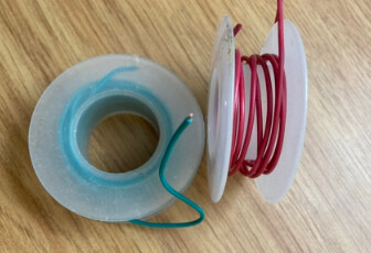
One other thing.... I recommend using wire that you cut to the length you need.... the wire in the picture is nice because it will plug into the protoboards but its bendable so you can keep things nice and organized vs the standard arduino wires that may be extra long
@dazpad, so did you manage to get the scales working correctly, I'm thinking of using an HX711 with 4x 50kg load cells under my water softener to get an alert when I'm running out of salt (just need to make sure that the machine plus 3-4 bags of salt is under the 200kg limit I would have before I start all this).
So I was wondering if you managed to get it working ok before I start ordering all this stuff.
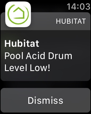
Yes it is working and I've been relying on it to let me know when either my acid or chlorine is low.
here's a screen capture from my Apple Watch:
There are a couple of caveats, though. Firstly, it's a hell of a thing to calibrate. Even placing the drum in a slightly different position on the load plate changes the weight reading and hence the litres readings. That being said I've worked out what the reading is when the drums are almost empty and use that in a couple of rules. The indicated remaining fluid doesn't exactly match what's actually left but it's good enough for my purposes.
The second thing I'm finding is that the voltage output seems to vary up and down by up to 0.4 of a volt. I don't know whether it's the signal conditioner I'm using or the Nano but every four or five samples will be lower or higher than the average. The usage graphs end up looking like this:
Thanks for the info @dazpad, here are a few things I noticed on your setup.
Is the cell oriented the correct way and did you leave a space between the cell and plates each side so that the cell is actually supporting the full weight and deforms as required like in this picture.
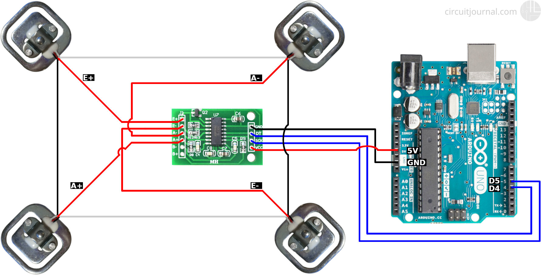
I believe that the biggest problem you may be having here is the load cell and the way it is used, with a large load like this I would have used 3 load cells in a triangle pattern or 4 in a square pattern, this would be a lot more stable than a single load cell (especially that type of cell) that may be struggling with twisting deformation because of the load that is balanced on the single cell.
Here is what I'll be trying as load cells for my application and think this would be better for your project.
I used to work in industrial automation and did have to work with load cells in the past, most times we had problems with unstable measurements, it was often ground potential problems and/or connections that were not well made or got corroded after a few years.
You caught my interest....on notifying if salt container is low.... i see from the pic that you get 4 sensors and 1 electrical board...can you explain how that works as it connects into an arduino.... is it a analog signal ? do you need 4 electrical boards ? thanks this sounds cool !
Thanks for your input, @nclark The cells are definitely setup correctly, with the spacers in place. I had the same thoughts you have regarding stability of the sensors, so I have each plate setup with two fixed "legs" on one side and a load cell on the opposite side. This means the cell is part of a tripod support arrangement, only taking a part of the load. The signal conditioners I used have both a zero and full scale adjustment, so I used an empty drum and zeroed out the voltage. I then used a full one to adjust to set the 5 volt max reading.
I think you could right regarding the voltage fluctuations. Firstly it would only take a small change at the input to the conditioner to result in a much larger output error. Secondly, I've have had issues getting a solid connection to the Nano pin sockets. I might have to solder direct to the board.
i was an Avionic Engineer before I retired. So many intermittent faults were traced back to corroded connectors or pushed back pins in mounting racks.
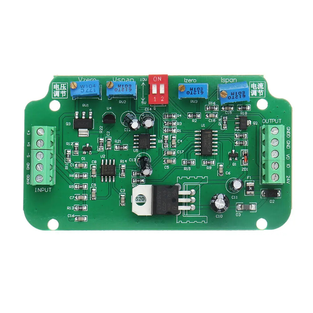
That was why I chose to use the 0 -5 volt output of the signal amp. I knew I could use the voltage child device to represent weight on the cell. There is no reason you couldn't run the four cells into a signal conditioner and amplify the output into usable voltage.
@dazpad, what board is that, might order one in case I don't succeed at getting the HX711 to work, even though I don't think it will be that hard to get it working and getting an equivalent to voltage output to HE.