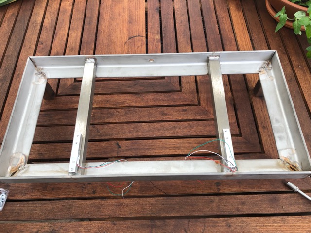
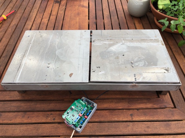
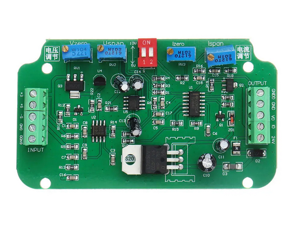
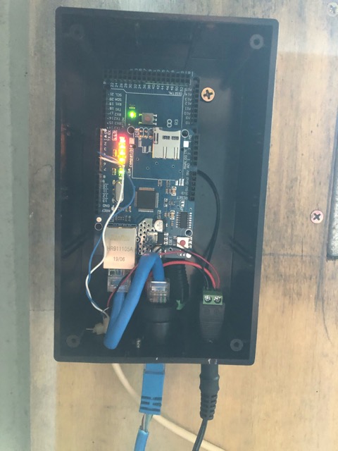
Here is the Sketch that I'm using
//******************************************************************************************
//  File: ST_Anything_Multiples_EthernetW5500.ino
//  Authors: Dan G Ogorchock & Daniel J Ogorchock (Father and Son)
//
//  Summary:  This Arduino Sketch, along with the ST_Anything library and the revised SmartThings
//            library, demonstrates the ability of one Arduino + Ethernet W5500 Shield to
//            implement a multi input/output custom device for integration into SmartThings.
//            The ST_Anything library takes care of all of the work to schedule device updates
//            as well as all communications with the Ethernet W5500 Shield.
//
//            ST_Anything_Multiples implements the following ST Capabilities in multiples of 2 as a demo of what is possible with a single Arduino
//              - 2 x Door Control devices (used typically for Garage Doors - input pin (contact sensor) and output pin (relay switch)
//              - 2 x Contact Sensor devices (used to monitor magnetic door sensors)
//              - 2 x Switch devices (used to turn on a digital output (e.g. LED, relay, etc...)
//              - 2 x Water Sensor devices (using an analog input pin to measure voltage from a water detector baord)
//              - 2 x Illuminance Measurement devices (using a photoresitor attached to ananlog input)
//              - 2 x Voltage Measurement devices (using a photoresitor attached to ananlog input)
//              - 2 x Smoke Detector devices (using simple digital input)
//              - 2 x Carbon Monoxide Detector devices (using simple digital input)
//              - 2 x Motion devices (used to detect motion)
//              - 2 x Temperature Measurement devices (Temperature from DHT22 device)
//              - 2 x Humidity Measurement devices (Humidity from DHT22 device)
//              - 2 x Relay Switch devices (used to turn on a digital output for a set number of cycles And On/Off times (e.g.relay, etc...))
//              - 2 x Button devices (sends "pushed" if held for less than 1 second, else sends "held"
//              - 2 x Alarm devices - 1 siren only, 1 siren and strobe (using simple digital outputs)
//
//            During the development of this re-usable library, it became apparent that the
//            Arduino UNO R3's very limited 2K of SRAM was very limiting in the number of
//            devices that could be implemented simultaneously.  A tremendous amount of effort
//            has gone into reducing the SRAM usage, including siginificant improvements to
//            the SmartThings Arduino library.
//
//            Note: This sketch was fully tested on an Arduino MEGA 2560 using the Ethernet2 W5500 Shield.
//
//  Change History:
//
//    Date        Who            What
//    ----        ---            ----
//    2015-01-03  Dan & Daniel   Original Creation
//    2017-02-12  Dan Ogorchock  Revised to use the new SMartThings v2.0 library
//    2017-04-16  Dan Ogorchock  New sketch to demonstrate multiple SmartThings Capabilties of each type
//    2017-04-22  Dan Ogorchock  Added Voltage, Carbon Monoxide, and Alarm with Strobe
//    2017-04-22  Dan Ogorchock  Initial version for W5500 Ethernet2 Shield
//    2018-02-09  Dan Ogorchock  Added support for Hubitat Elevation Hub
//
//******************************************************************************************
//******************************************************************************************
// SmartThings Library for Arduino Ethernet W5500 Shield
//******************************************************************************************
#include <SmartThingsEthernetW5500.h>    //Library to provide API to the SmartThings Ethernet W5500 Shield

//******************************************************************************************
// ST_Anything Library
//******************************************************************************************
#include <Constants.h>       //Constants.h is designed to be modified by the end user to adjust behavior of the ST_Anything library
#include <Device.h>          //Generic Device Class, inherited by Sensor and Executor classes
#include <Sensor.h>          //Generic Sensor Class, typically provides data to ST Cloud (e.g. Temperature, Motion, etc...)
#include <Executor.h>        //Generic Executor Class, typically receives data from ST Cloud (e.g. Switch)
#include <InterruptSensor.h> //Generic Interrupt "Sensor" Class, waits for change of state on digital input
#include <PollingSensor.h>   //Generic Polling "Sensor" Class, polls Arduino pins periodically
#include <Everything.h>      //Master Brain of ST_Anything library that ties everything together and performs ST Shield communications

#include <PS_Illuminance.h>  //Implements a Polling Sensor (PS) to measure light levels via a photo resistor on an analog input pin
#include <PS_Voltage.h>      //Implements a Polling Sensor (PS) to measure voltage on an analog input pin
#include <PS_TemperatureHumidity.h>  //Implements a Polling Sensor (PS) to measure Temperature and Humidity via DHT library
#include <PS_Water.h>        //Implements a Polling Sensor (PS) to measure presence of water (i.e. leak detector) on an analog input pin
#include <IS_Motion.h>       //Implements an Interrupt Sensor (IS) to detect motion via a PIR sensor on a digital input pin
#include <IS_Contact.h>      //Implements an Interrupt Sensor (IS) to monitor the status of a digital input pin
#include <IS_Smoke.h>        //Implements an Interrupt Sensor (IS) to monitor the status of a digital input pin
#include <IS_CarbonMonoxide.h> //Implements an Interrupt Sensor (IS) to monitor the status of a digital input pin
#include <IS_DoorControl.h>  //Implements an Interrupt Sensor (IS) and Executor to monitor the status of a digital input pin and control a digital output pin
#include <IS_Button.h>       //Implements an Interrupt Sensor (IS) to monitor the status of a digital input pin for button presses
#include <EX_Switch.h>       //Implements an Executor (EX) via a digital output to a relay
#include <EX_Alarm.h>        //Implements Executor (EX)as an Alarm capability with Siren and Strobe via digital outputs to relays
#include <S_TimedRelay.h>    //Implements a Sensor to control a digital output pin with timing/cycle repeat capabilities

//**********************************************************************************************************
//Define which Arduino Pins will be used for each device
//  Notes: Arduino communicates with both the W5500 and SD card using the SPI bus (through the ICSP header).
//         This is on digital pins 10, 11, 12, and 13 on the Uno and pins 50, 51, and 52 on the Mega.
//         On both boards, pin 10 is used to select the W5500 and pin 4 for the SD card.
//         These pins cannot be used for general I/O. On the Mega, the hardware SS pin, 53,
//         is not used to select either the W5500 or the SD card, but it must be kept as an output
//         or the SPI interface won't work.
//         See https://www.arduino.cc/en/Main/ArduinoEthernetShield for details on the W5500 Sield
//**********************************************************************************************************
//"RESERVED" pins for W5500 Ethernet Shield - best to avoid
#define PIN_4_RESERVED            4   //reserved by W5500 Shield on both UNO and MEGA
#define PIN_1O_RESERVED           10  //reserved by W5500 Shield on both UNO and MEGA
#define PIN_11_RESERVED           11  //reserved by W5500 Shield on UNO
#define PIN_12_RESERVED           12  //reserved by W5500 Shield on UNO
#define PIN_13_RESERVED           13  //reserved by W5500 Shield on UNO
#define PIN_50_RESERVED           50  //reserved by W5500 Shield on MEGA
#define PIN_51_RESERVED           51  //reserved by W5500 Shield on MEGA
#define PIN_52_RESERVED           52  //reserved by W5500 Shield on MEGA
#define PIN_53_RESERVED           53  //reserved by W5500 Shield on MEGA

//Digital Pins
//Digital Pins
#define PIN_SWITCH_1              22  //Living Room Speakers
#define PIN_SWITCH_2              23  //Kitchen Speakers
#define PIN_SWITCH_3              24  //Kids Bedroom Speakers
#define PIN_SWITCH_4              25  //Master Bedroom Speakers
#define PIN_SWITCH_5              26  //Master Bathroom Speakers
#define PIN_SWITCH_6              27  //Source1 switch to Source2
//#define PIN_SWITCH_7              40  //SmartThings Capability "Switch"


//---Begin Push Button declarations---
#define MAX_PUSHBUTTONS 6
#define MIN_DEBOUNCE_TIME 50 //push-buttons must be held for 50ms to prevent chattering input

#define PIN_BUTTON1   30
#define PIN_BUTTON2   31
#define PIN_BUTTON3   32
#define PIN_BUTTON4   33
#define PIN_BUTTON5   34
#define PIN_BUTTON6   35


byte nBtnIndex;      //Index Variable
bool nCurrentVal;     //temp variable
String strCommand;
byte nBtnVals[MAX_PUSHBUTTONS][2];   //Array of current[0] and last[1] values of the pushbuttons
byte nBtnPins[MAX_PUSHBUTTONS] = {PIN_BUTTON1, PIN_BUTTON2, PIN_BUTTON3, PIN_BUTTON4, PIN_BUTTON5, PIN_BUTTON6};
unsigned long lngBtnLastMillis[MAX_PUSHBUTTONS]; //needed to properly debounce the pushbutton inputs
st::EX_Switch* swArray[MAX_PUSHBUTTONS]; //need an array of the executors so we can togle the correct one
//---End Push Button declarations---


//******************************************************************************************
//W5500 Ethernet Shield Information
//******************************************************************************************
byte mac[] = {0x2C, 0xF7, 0xF1, 0x08, 0x0C, 0x38}; //MAC address                                 //  <---You must edit this line using the MAC address provided with your W5500 Shield!
IPAddress ip(192, 168, 1, 221);               //Arduino device IP Address                   //  <---You must edit this line!
IPAddress gateway(192, 168, 1, 1);            //router gateway                              //  <---You must edit this line!
IPAddress subnet(255, 255, 255, 0);           //LAN subnet mask                             //  <---You must edit this line!
IPAddress dnsserver(192, 168, 1, 1);          //DNS server                                  //  <---You must edit this line!
const unsigned int serverPort = 8090;         // port to run the http server on

// Smartthings / Hubitat Hub TCP/IP Address
IPAddress hubIp(192, 168, 1, 226);    // smartthings/hubitat hub ip //  <---You must edit this line!

// SmartThings / Hubitat Hub TCP/IP Address: UNCOMMENT line that corresponds to your hub, COMMENT the other
//const unsigned int hubPort = 39500;   // smartthings hub port
const unsigned int hubPort = 39501;   // hubitat hub port

//******************************************************************************************
//st::Everything::callOnMsgSend() optional callback routine.  This is a sniffer to monitor
//    data being sent to ST.  This allows a user to act on data changes locally within the
//    Arduino sktech withotu having to rely on the ST Cloud for time-critical tasks.
//******************************************************************************************
void callback(const String &msg)
{
  //Uncomment if it weould be desirable to using this function
  //Serial.print(F("ST_Anything_Miltiples Callback: Sniffed data = "));
  //Serial.println(msg);

  //TODO:  Add local logic here to take action when a device's value/state is changed

  //Masquerade as the ThingShield to send data to the Arduino, as if from the ST Cloud (uncomment and edit following line(s) as you see fit)
  //st::receiveSmartString("Put your command here!");  //use same strings that the Device Handler would send
}

//******************************************************************************************
//Arduino Setup() routine
//******************************************************************************************
void setup()
{
  //******************************************************************************************
  //Declare each Device that is attached to the Arduino
  //  Notes: - For each device, there is typically a corresponding "tile" defined in your
  //           SmartThings Device Hanlder Groovy code, except when using new COMPOSITE Device Handler
  //         - For details on each device's constructor arguments below, please refer to the
  //           corresponding header (.h) and program (.cpp) files.
  //         - The name assigned to each device (1st argument below) must match the Groovy
  //           Device Handler names.  (Note: "temphumid" below is the exception to this rule
  //           as the DHT sensors produce both "temperature" and "humidity".  Data from that
  //           particular sensor is sent to the ST Hub in two separate updates, one for
  //           "temperature" and one for "humidity")
  //         - The new Composite Device Handler is comprised of a Parent DH and various Child
  //           DH's.  The names used below MUST not be changed for the Automatic Creation of
  //           child devices to work properly.  Simply increment the number by +1 for each duplicate
  //           device (e.g. contact1, contact2, contact3, etc...)  You can rename the Child Devices
  //           to match your specific use case in the ST Phone Application.
  //******************************************************************************************

  //Executors
  static st::EX_Switch              executor1(F("switch1"), PIN_SWITCH_1, LOW, true);
  static st::EX_Switch              executor2(F("switch2"), PIN_SWITCH_2, LOW, true);
  static st::EX_Switch              executor3(F("switch3"), PIN_SWITCH_3, LOW, true);
  static st::EX_Switch              executor4(F("switch4"), PIN_SWITCH_4, LOW, true);
  static st::EX_Switch              executor5(F("switch5"), PIN_SWITCH_5, LOW, true);
  static st::EX_Switch              executor6(F("switch6"), PIN_SWITCH_6, LOW, true);
  // static st::EX_Switch              executor7(F("switch7"), PIN_SWITCH_7, LOW, true);


  //*****************************************************************************
  //  Configure debug print output from each main class
  //*****************************************************************************
  st::Everything::debug = true;
  st::Executor::debug = true;
  st::Device::debug = true;
  st::PollingSensor::debug = true;
  st::InterruptSensor::debug = true;

  //*****************************************************************************
  //Initialize the "Everything" Class
  //*****************************************************************************

  //Initialize the optional local callback routine (safe to comment out if not desired)
  st::Everything::callOnMsgSend = callback;

  //Create the SmartThings EthernetW5500 Communications Object
  //STATIC IP Assignment - Recommended
  st::Everything::SmartThing = new st::SmartThingsEthernetW5500(mac, ip, gateway, subnet, dnsserver, serverPort, hubIp, hubPort, st::receiveSmartString);

  //DHCP IP Assigment - Must set your router's DHCP server to provice a static IP address for this device's MAC address
  //st::Everything::SmartThing = new st::SmartThingsEthernetW5500(mac, serverPort, hubIp, hubPort, st::receiveSmartString);

  //Run the Everything class' init() routine which establishes Ethernet communications with the SmartThings Hub
  st::Everything::init();

  //*****************************************************************************
  //Add each sensor to the "Everything" Class
  //*****************************************************************************

  //*****************************************************************************
  //Add each executor to the "Everything" Class
  //*****************************************************************************
  st::Everything::addExecutor(&executor1);
  st::Everything::addExecutor(&executor2);
  st::Everything::addExecutor(&executor3);
  st::Everything::addExecutor(&executor4);
  st::Everything::addExecutor(&executor5);
  st::Everything::addExecutor(&executor6);
  //  st::Everything::addExecutor(&executor7);
  //*****************************************************************************
  //Initialize each of the devices which were added to the Everything Class
  //*****************************************************************************
  st::Everything::initDevices();
  //*****************************************************************************
  //Add User Customized Setup Code Here (instead of modifying standard library files)
  //*****************************************************************************
  //---Begin Push Button initialization section---
  swArray[0] = &executor1;
  swArray[1] = &executor2;
  swArray[2] = &executor3;
  swArray[3] = &executor4;
  swArray[4] = &executor5;
  swArray[5] = &executor6;

  //Allocate strCommand buffer one time to prevent Heap Fragmentation.
  strCommand.reserve(20);

  //Configure input pins for hardwired pusbuttons AND read initial values
  for (nBtnIndex = 0; nBtnIndex < MAX_PUSHBUTTONS; nBtnIndex++) {
    pinMode(nBtnPins[nBtnIndex], INPUT_PULLUP);
    nBtnVals[nBtnIndex][0] = digitalRead(nBtnPins[nBtnIndex]);   // read the input pin
    nBtnVals[nBtnIndex][1] = nBtnVals[nBtnIndex][0];
    lngBtnLastMillis[nBtnIndex] = 0;  //initialize times to zero
  }
  //---End Push Button initialization section---
}


//******************************************************************************************
//Arduino Loop() routine
//******************************************************************************************
void loop()
{
  //*****************************************************************************
  //Execute the Everything run method which takes care of "Everything"
  //*****************************************************************************
  st::Everything::run();
  //*****************************************************************************
  //Add User Customized Loop Code Here (instead of modifying standard library files)
  //*****************************************************************************

  //---Begin Push Button execution section---
  //Loop through the pushbutton array
  for (nBtnIndex = 0; nBtnIndex < MAX_PUSHBUTTONS; nBtnIndex++)
  {
    nCurrentVal = digitalRead(nBtnPins[nBtnIndex]); // read the input pin
    if (nCurrentVal != nBtnVals[nBtnIndex][1])      // only act if the button changed state
    {
      lngBtnLastMillis[nBtnIndex] = millis();  //keep track of when the button changed state
    }
    if ((millis() - lngBtnLastMillis[nBtnIndex] >= MIN_DEBOUNCE_TIME) && (nBtnVals[nBtnIndex][0] != nCurrentVal))
    {
      nBtnVals[nBtnIndex][0] = nCurrentVal; //keep current value for proper debounce logic
      if (nCurrentVal == LOW)    //only care if the button is pressed (change LOW to HIGH if logic reversed)
      {
        strCommand = swArray[nBtnIndex]->getName() + " " + (swArray[nBtnIndex]->getStatus() == HIGH ? "off" : "on");
        Serial.print(F("Pushbutton: "));
        Serial.println(strCommand);
        swArray[nBtnIndex]->beSmart(strCommand);  //Call the beSmart function of the proper executor object to either turn on or off the relay
        strCommand.remove(0); //clear the strCommand buffer
      }
    }
    nBtnVals[nBtnIndex][1] = nCurrentVal;  //keep last value for proper debounce logic
  }
  //---End Push Button execution section---
}