I am seeing the exact same behavior. I will have to debug the issue to see what has changed. It has been a long time since anyone has asked about the PC_Pulse device... It may work fine on an Arduino MEGA, as that may have been what it was originally written for...???
Chris,
I think I found it, but would appreciate your assistance in testing the temporary fix that works only on the ESP8266 based boards...
within PS_PulseCounter.cpp, change the following
from
	void isrPulse() {
		m_nCounts++;
	}
to
	void ICACHE_RAM_ATTR isrPulse() {
		m_nCounts++;
	}
Let me know if the board becomes stable afterwards. Mine did. I did not test whether the pulse counting works or not, though! Too late, and I need to get some sleep. If this works for you, I'll implement a permanent fix in the code that works with multiple boards.
Dan
1 Like
Hi Dan,
That did the trick... I found the articles on the ICACHE_RAM_ATTR but could not work out where in the code to put it... Many thanks for your help.. Now to see if the pulse counting works. Will update when I have it working if it helps others.
Cheers Chris
1 Like
I was planning on running 2 servos on one ESP8266, and a 3rd servo on a 2nd ESP. Is there any limitation on running all 3 servos on 1 ESP?
Or perhaps a abetter way to phrase the question: How many servos could I run on 1 ESP before performance would be impacted?
@ogiewon
Very EXCITED!!! Been working on getting an MCP23008 working, since the NodeMCU is limited in outputs that don't have restrictions/caveats.
I GOT IT TO WORK JUST NOW!!!! I had to create a clone library file for S_TimedRelay to call the MCP23008 pinMode and digitalWrite functions... but that is OK. It will allow direct pin assignment with the base file. Should work fine with a MCP230017 as well, just need to have the library and change the include, etc.
1 Like
Chris,
I have updated my GitHub repository with a revised version of PS_PulseCounter.cpp that should work on both older Arduino boards, as well as the ESP8266 boards. You may want to grab that latest version to make sure your copy is up to date.
Dan
I assume you're powering the Servos directly from a power supply, and not from the ESP8266's 3.3v pin? Trying to pull three servos' worth of current from that tiny voltage regulator is most likely not going to work. However, as long as you power the servos directly from the power supply, and as long as that power supply is powerful enough for all three servos + the ESP8266, I think it should work without a problem. Just be certain to use the 'safest pins' on the ESP8266 (D1, D2, D5, D6, D7). See the chart in my ReadMe for details of my testing of the NodeMCU ESP8266's GPIO pins. I cannot gurantee that all three servos will work correctly, but it is worth a try.
If you don't want independent control of all three servos, you might be able to tie the three data/signal wires together and only use 1 GPIO pin. All three would then behave the same, I believe. This would not give you any per blind tuning ability, though.
[Updated to avoid any confusion in the future regarding the number of GPIO pins required per servo motor.]
Thanks for the feedback! Yes, I would use a separate PS.
Re your statement about tying the three signal wires together: Why would I need 2 x GPIO pins? It sounds as if I would only need 1? Or?
1 Like
Ahhh yes, you are correct! I was thinking about steppers, which require two signal wires instead of 1 for the servo motors. Sorry for the confusion.
In that case, I would use D5, D6, and D7 for independent control.
Just to confirm:
In your 1st response you weren't sure that it would work. However now that we are on the same page, would 3 servos (not steppers) work on the ESP8266 - with an external PS?
Yes, I believe they still would work. I have used two at a time during testing, each having its own GPIO pin. This then results in multiple devices appearing in Hubitat, each controlled individually if desired.
Thnaks Dan..
I have got the pulse counting going and am feeding it with a steady blinking LED to test. The readings are all over the place and not consistent. I have utilised the pulse sensor from a watts clever meter which does read the correct number of pulses. Just cant get it to read consistently will the ESP8266. Sensor is connected between the GPIO pin and ground which I assume, pulls the pin to ground when there is a pulse. Any ideas what I might be doing wrong or how to test the interrupt is being read correctly.Cheers Chris
Chris,
The PS_Pulse Counter device uses interrupts to count the number of times a digital input pin either RISES, FALLS, or CHANGES within a specific polling period of time. That total is then multiplied by a slope and added to an offset (y=mx+b) before being sent to Hubitat as a power monitoring device.
As is detailed below, you can choose whether or not to use the internal pullup resistor feature which is only available on some of the GPIO pins of the ESP8266 board. Be sure to use pins D1, D2, D5, D6, or D7 for your testing. These are the safest and most fully featured pins you can use.
Using the example declaration, we can see that the internal pullup resistor is being used. So, simply connect jumper wire to ground, and then touch PIN_PULSE repeatedly with the other end of the jumper. After 60 seconds, the total value will be multiplied time 1.0, then added to 0, and then sent to the hub as the "power1" device.
I just ran a very simple test on my NodeMCU ESP8266 and it appears to be working fine using pin D1. It should be noted that it will be almost impossible for you to use a jumper wire, as described above, to get accurate numbers. For example, trying to touch the D1 pin to ground by hand one time will actually result in multiple values being registered due to the sensitivity of the input and the instability of the human hand.
static st::PS_PulseCounter sensor1(F("power1"), 60, 5, PIN_PULSE, FALLING, INPUT_PULLUP, 1.0, 0);
//			  Create an instance of this class in your sketch's global variable section
//			  For Example:  st::PS_PulseCounter sensor3(F("power1"), 60, 5, PIN_PULSE, FALLING, INPUT_PULLUP, 1.0, 0);
//
//			  st::PS_PulseCounter() constructor requires the following arguments
//				- String &name - REQUIRED - the name of the object - must be in form of "power1", "power2", etc...
//				- int interval - REQUIRED - the polling interval in seconds
//				- int offset - REQUIRED - the polling interval offset in seconds - used to prevent all polling sensors from executing at the same time
//				- byte pin - REQUIRED - the GPIO Pin to be used as an digital input (Hardware Interrupt)
//				- byte inttype - REQUIRED - which type of Arduino interrupt to trigger the ISR (RISING, FALLING, CHANGE)
//				- byte inputmode - REQUIRED - Mode of the digital input Pin (INPUT, INPUT_PULLUP)
//				- float cnvslope - REQUIRED - Conversion to Engineering Units Slope
//				- float cnvoffset - REQUIRED - Conversion to Engineering Units Offset
Dan
Thanks for that... Have cleaned up the pulse signal with a capacitor across the sensor. The oscilloscope is now showing a very clean signal with virtually no noise.
The values are still all over the shop but graphing the readings, there is a pattern.
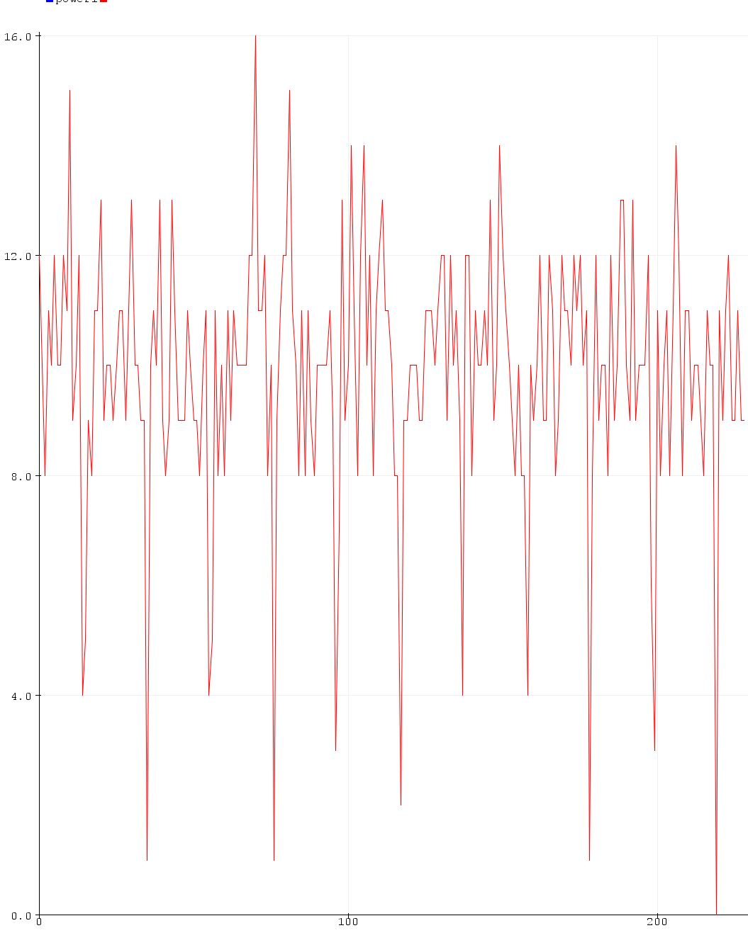
The low readings are very regular. Interesting
1 Like
In subsequent posts you indicated you were having some problems. I would appreciate it if you provide some details:
What does your final power delivery to your board and servos consist of?
Is there a need to have separate power supplies for the board and servos? (I am thinking of getting just one 5A 12V PS with 2-3 buck converters for the board and 3 x servos)
Do you have links to the PS and Bucks you used?
Right now I have 1 7v power supply and one 5v buck converter set up.
No, the reason I had to have 7v power is because the "beefier" servo I bought requires 6-7.6v of power. It would run with 5v but was definitely not as strong as it could have been.
I have one board, and one servo per window. In most cases I have one 120 to 5v supply that is big enough for the combo of what I have their. In my bedroom I have a 2A supply and I run the servo and the board directly off the supply, NOT off the pins.
In my kitchen, I have 3 boards, a string on 50 neopixels and my servo all at the headrail of my kitchen blinds. So, there I have a 7A supply to run all of that. Remember, you alway want to factor in 25% wiggle room at the top. Never run your supply at near capacity. In this setup I could have gotten away with less if I had more control over the timing but I found that when I had a 5A supply, if I had the LEDs at max brightness and moved the blinds a long way(75%) I would get a board reset and screw everything up.
Everything I bought was on Amazon US. I have no idea how high a quality they are, I just took a stab in the dark and hoped for the best. I don't have specific links to everything and not really sure what good they would do for you. You can search Amazon as well as I can.
Dan,
Finally got round to testing this, and it works! Had three servos on the one ESP8266! Will have to see how this works out under load.
I did however encounter a side issue:
In HE I created a group, that contained the three child servos. Now since I plan to control blinds (which don't require speed), I had set the Rate on each's device page to 3500 mS. Controlling each servo individually they do move at this slowed rate. In a Rule, listing them indivually works fine. However, the Group reverts to Max - in dimmer/level sliders, in a rule, whatever - and all the servos move at speed. This is not good.
Any ideas?
What do you mean by group? Did you create a Hubitat group for the three devices or are you just listing them all in the same action within a rule? A copy of your rule would be helpful. Are you setting the fade time in your rule?
Clearly stated: "In HE I created a group, that contained the three child servos". Then added a tile for the group in a dashboard - either as a Dimmer or Level Vertical, both of which will revert the servos to max speed. There is no issue with the rule - the point being if I select the individual servos, no problem, but if I select the Group, then they all revert to max speed - just like with the dashboard tile sliders . . . .
Please monitor the Arduino IDE Serial Monitor Window to see what is different between individually sending commands to each servo, and sending commands via the Hubitat Group. I can't imagine why the Arduino code would behave any differently as it is simply expecting a SWITCH/LEVEL command to be issued.