The output from this sensor is a series of pulses. Frequency of pulses is proportional to flow rate. You can use a "Pulse Counter" component and calculate flow rate right in the Hubduino/Arduino sketch. Please make sure output voltage fron sensor is matched to the CPU input voltage. If both are the same the direct connection of the sensor output to the CPU input will work. Otherwise you will need a voltage translator in between.
1 Like
As metioned by @vitaliy_kh, the PS_PulseCounter device is what you most likely want.
//******************************************************************************************
//  File: PS_PulseCounter.cpp
//  Authors: Dan G Ogorchock & Daniel J Ogorchock (Father and Son)
//
//  Summary:  PS_PulseCounter is a class which implements the SmartThings "Power Meter"-style device capability.
//			  It inherits from the st::PollingSensor class.  The current version uses a digital input to measure the
//			  the number of counts between polling intervals.  At the polling interval, the pulse count is converted
//			  to engineering units via a linear conversion (engUnits = slope x counts + offset).
//
//
//			  Create an instance of this class in your sketch's global variable section
//			  For Example:  st::PS_PulseCounter sensor3(F("power1"), 60, 5, PIN_PULSE, FALLING, INPUT_PULLUP, 1.0, 0);
//
//			  st::PS_PulseCounter() constructor requires the following arguments
//				- String &name - REQUIRED - the name of the object - must be in form of "power1", "power2", etc...
//				- int interval - REQUIRED - the polling interval in seconds
//				- int offset - REQUIRED - the polling interval offset in seconds - used to prevent all polling sensors from executing at the same time
//				- byte pin - REQUIRED - the GPIO Pin to be used as an digital input (Hardware Interrupt)
//				- byte inttype - REQUIRED - which type of Arduino interrupt to trigger the ISR (RISING, FALLING, CHANGE)
//				- byte inputmode - REQUIRED - Mode of the digital input Pin (INPUT, INPUT_PULLUP)
//				- float cnvslope - REQUIRED - Conversion to Engineering Units Slope
//				- float cnvoffset - REQUIRED - Conversion to Engineering Units Offset
This device uses hardware interrupts on the microcontroller to collect data. Data is accumulated and then transmitted to the HE Hub periodically.
Thank you ogiewon, like usual your skills are top shelf!!!
1 Like
I'm trying to add a pushbutton child device that will detect a continuity signal from my hikvision ds-kv6113-wpe1 door station. I have enabled the door station's pushbutton to output to the NO contacts and wired it to 2560 pins 18 and ground. I then added these lines .... #include <IS_Button.h> //Implements an Interrupt Sensor (IS) to monitor the status of a digital input pin for button presses
#define PIN_BUTTON1 18 //SmartThings Capabilty Button / Holdable Button (Doorbell)
static st::IS_Button sensor17(F("button1"), PIN_BUTTON1, 1000, LOW, true, 500);
st::Everything::addSensor(&sensor17); //Doorbell button .... but no child device gets created. I've refreshed the parent device as well as rebooted the C8 Pro to no avail.
This behavior is expected. There are no child devices created for push buttons. The parent device will generate these events directly. Just add the parent device to your automation as the trigger, as a button controller device.
Thanks Again ...
1 Like
Potential Bug in the "Hubduino Component Valve" driver.
I just finished Hubduino Controller for the Delta Touch2O Solenoid Valve. Everything is working just fine and Valve State is correctly reported for either Manunual or Commnad control. However when I tryed to use Valve State in the RM Condition the Condition is always FALSE regardles of Valve State:

Is this a problem with a "Hubduino Component Valve" custom driver or something is not right with the HE Platform?
UPDATE
It looks like problem with a Custom Driver. For testing I created a Virtual Valve and for this one everything looks right:

I cannot reproduce this issue. Rule Machine happily handles using my HubDuino Component Vlave driver devices for a condition. I actually used it as the Required Expression for a test rule that I just created. Worked perfectly.
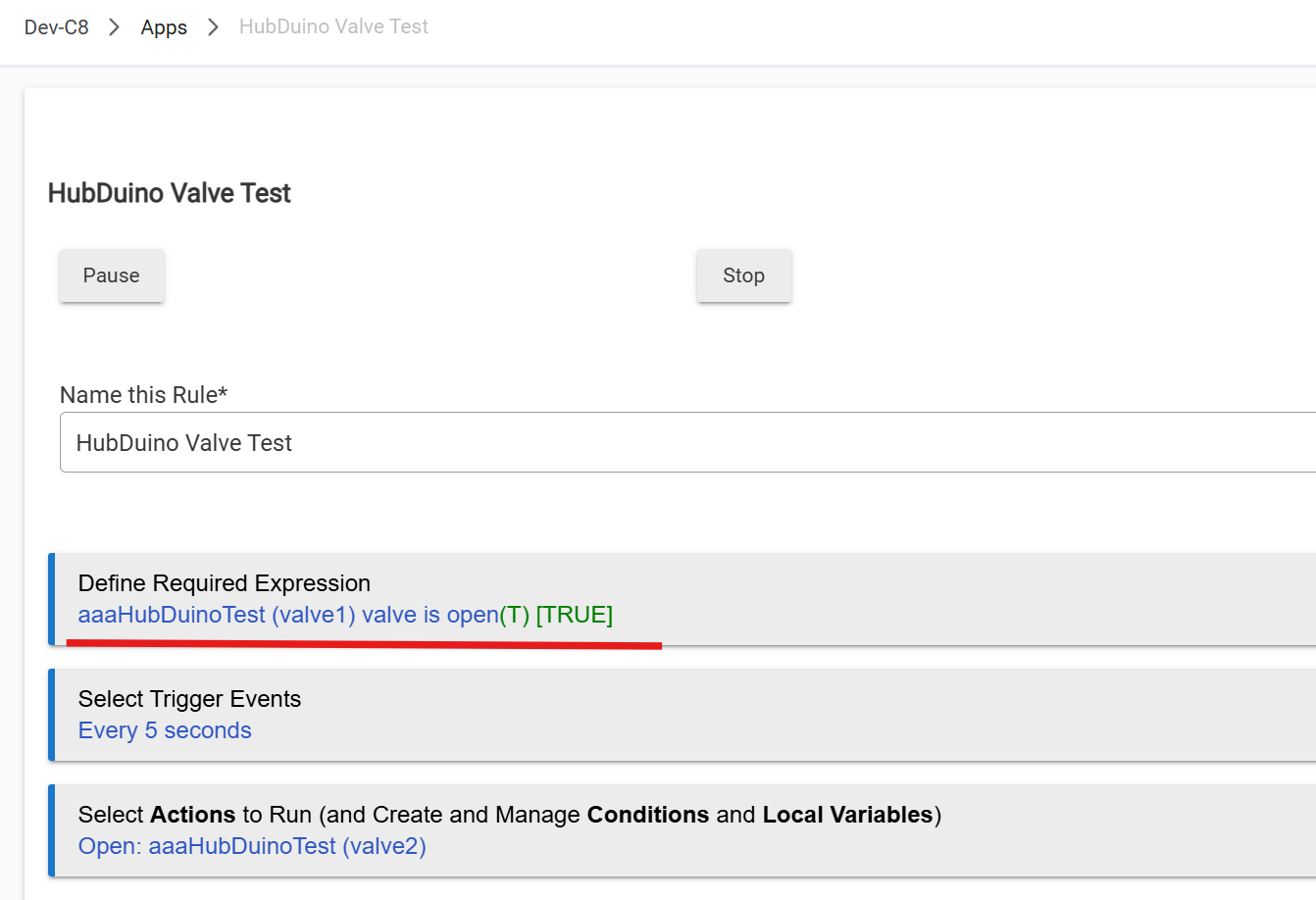
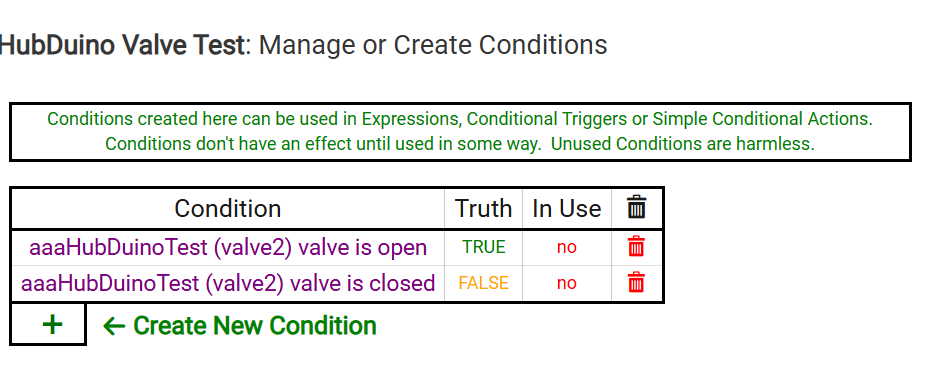
I added two Conditions just to verify that it is not always false. Here you go...
Have you customized any of the code?
I forgot to mention, Valve Component is set by Hubduino sketch and used only as a reported status:
// ***** Report Valve Status to HE *****
void ReportValveStatus()
{
  if (memcmp(bufferRx, StatusString_ValveOpened, STATUS_PACKET_LEN) == 0)
  {
    smartthing.send("valve1 open");
  }
  else if (memcmp(bufferRx, StatusString_ValveClosed, STATUS_PACKET_LEN) == 0)
  {
    smartthing.send("valve1 close");
  }
}
Does this makes a difference and a reson why RM Condition is always FALSE?
In few other Hubduino projects I am using the same techique to set/reset Switch and Contact components. This works perfectly fine. However the used drivers are buil-in Generic Switch and Generic Contact. In this case Valve is a custom driver.
I can use ether Switch or Contach component for reporting Valve status but this will be harder to maintain and reduce code readability.
Change “close“ to “closed”
Many BIG Thanks! That was it.
One more question to you.
While dealing with this latest project Arduino IDE got multiple updates (Boards and Libraries).
And right now all my projects lost an OTA ability. I.e IP Ports are not listed anymore, only Serial ports are available:
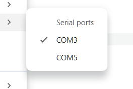
Do you have an idea how to fix/restore this OTA Capability?
@ogiewon I will continue to praise your efforts for this project, I have found so many ways to make use of this, many thanks!!
I recently changed wifi networks at home so I needed to update a d1 mini board for a PWM project I implemented years ago and never changed since(Link to post). When using it last i noticed that when setting the level around 25% the SSR I had attached to would just be full power not "dimmed" like it was between 0-99 (like the PWM project specifies).
After a bunch of digging and AI help I found that the ESP8266 D1 Mini boards I am using changed the PWM resolution on the core board from 0-1023 to 0-255, effectively making anything above 255 at 100% (I think I am explaining this correctly!?).
The Fix
To fix this I had to modify the EX_PWM_Dim.cpp and replace the following in 4 different places:
analogWrite(m_nPinPWM, map(m_nCurrentLevel, 0, 100, 0, 1023));
with
analogWrite(m_nPinPWM, map(m_nCurrentLevel, 0, 100, 0, 255));
I'll admit I understand logically at a high level how this all works, but I do not understand how each part works exactly, nor do I understand how to code. So while this solved my issue for now, I believe that this is more of a bandaid than a permanent fix of the PWM component due to the way the core for these ESP8266 board changed. So I am elevating to this group to see if there is someone out there that would be willing to look at and re-write the PWM component to factor in the new 1023 resolution?
Again for give my mistakes if there is anything that i misspoke or mislabeled in this post  . Happy to chime in more if there is anything that needs clarified.
1 Like
Thank you for the great feedback. I’ll take a look at the issue and possible fixes after this week’s festivities.
1 Like
I also want to say BIG THANKYOU for this wonderful project!
Thanks to Hubduino now I can build whatever I want. Hubduno helped me to get rid from number of cloud-based integrations and make things 100% locally controlled. I even bought a CNC Router with Spindel and Laser Head for making custom PCBs and a 3D Printer for custom cases. Here is a list of already complete projects:
- Local Controller for the Delata Touch2O faucet (I need only an Valve On/Off control but project is capable to do valume dispence and report a water temp);
- SmartBed Controller for the Reverie 5D SmartBed Base (one for each bed);
- Autoslide MODBUS Controller;
- DC Linear Actuator Controller for Balcony Swing Door;
- DC Linear Actuator Controllers for the Kitchen Undersink Cabinets;
There are few more projects on a TO DO list.
Few of the above projects will be impossible to create without Hubduino.
Few other automations is possible to create with ready-to-go Zigbee/ZWave toys but they are not staigh forward.
Once again - BIG THANKYOU for the Hubduino project and
Happy Holidays!
2 Likes
Again, thank you for the feedback. It appears that when the v3.x of the Arduino board support package for the ESP8266 was released a while back, they decided to change the range for the AnalogWrite() call for the ESP8266 from 0-1023 to 0-255, to match all of the other Arduino boards. Back in 2019, I actually modified the code to properly support the ESP8266's original 0-1023 range. I guess it is time to revert that change.
I'll let you know when I release the change so you can test it out.
Thank you!
Could you please make this parameter configurable?
I really like wider PWM Range support in hardware. I could be easely downgraded in the SW but not a vice versa.
1 Like
@b.m.oxendale and @vitaliy_kh - I have updated the following files in my GitHub repo for your testing pleasure.
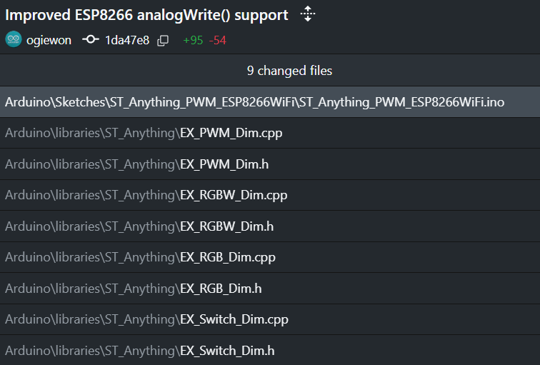
They should now properly support the ESP8266 boards on the ESP8266 v3.x board manager.
I have added an optional parameter to the Constructor of each of these ST_Anything device types, with a default value of 1023. This value is passed into a analogWriteRange() call in the contructor of each device, which makes the proper analogWriteRange call and stores the value in a private member variable called m_analogWriteRange. This variable is used in all of the ESP8266 specific map() calls to properly scale the values before calling analogWrite().
Please give these updated files a test and let me know if this resolves the issue.
Thank you!
@ogiewon - I updated my libraries folder and reloaded my sketch this morning, and it works great, just as it did before!!
The only thing I was going to mention is that in the comments on the EX_PWM_Dim.h/.cpp where you are detailing out how the constructor should be formatted, you state:
// -unsigned short analogWriteRangeVal - OPTIONAL - determines the range of input values for the analogWrite() call for only the ESP8266 boards. Defaults to 1023 for backwards compatibility.
Should this be "...Defaults to 255 for backwards compatibility"?
Another question, in this same section where you are detailing out the formatting of the constructor it is stated that both of these parameters are required:
// - byte pin - REQUIRED - the Arduino Pin to be used as a digital output
// - byte pin_pwm - REQUIRED - the Arduino Pin to be used as a pwm output
But my current sketch (based off the "ST_Anything_PWM_ESP8266WiFi.ino" example sketch only has this as the constructor:
static st::EX_PWM_Dim executor4(F("dimmerSwitch1"), PIN_LEVEL_1, LOW, false);
Essentially, not using the "pin" digital output, so is it not required?
Forgive my naivety
Regardless, thanks for the quick fix, it works great!!
Yes, I believe this was an original typo from back when this file was originally created by another user, who based it off of the original device which included both Switch and Dim functionality. I'll clean up the comment section. Thank you for the feedback. (Or maybe I just introduced this typo with too much copying and pasting???  ) In either event, it will be cleaned up.
Nope, I left it defaulting to 1023 as that is what I believe will cause the least impact to end users. Since the old ESP8266 SDK for Arduino used 0 to 1023, I made sure that the new one (which does default to 0 to 255) uses the proper override to set the range back to 0 to 1023. If a user wants to set that range to 0 to 255, they can do so by passing in the proper parameter to the constructor.
Yep, again that appears to be a carry-over from the original that was missed. I'll clean it up.
I have updated the EX_PWM_Dim.h and .cpp files in my GitHub repo with the improved comments sections. Thanks!