I am having a blast! This is the best app on the forum in my opinion... maybe a close tie with Alexa speaks. I was frustrated trying to get my W5100 board working and finally decided it was faulty so I switched to a Node MCU and everything started working perfectly. Thanks so much for making this great integration.
1 Like
I am looking for a little help on this as what I thought was going to be simple appears not to be so.
I currently run an Arduino Mega 2460 with a LAN shield on it, all that's okay. But it runs my current motion sensors and a simple power detection thing for Homeseer.
What I thought (hoped) I'd be able to do was read the device states in Hubitat and slowly migrate from HS to Hubitat but I don't know and can't see if this is possible. HS uses a COM port on a direct USB connection, the LAN is unused presently so I'd hoped I could "read" the board info from the LAN to Hubitat whilst, for the time being, preserving the HS setup.
Moving all the sensors, routines etc in one go would be a major operation and, not at all easy.
However, I fell at the first hurdle as for the life of me I can't see what I need to install on Hubitiat to even get started.
Any pointers in the right direction I'd really appreciate.
Unless you are a very proficient C/C++ programmer, trying to modify your existing Arduino sketch to be able to communicate with both Homeseer and Hubitat at the same time is going to be very challenging.
HubDuino is designed to be the one and only piece of code running on the microcontroller. There are communications libraries within it that could be used to add functionality to an existing sketch, but that type of effort is pretty much beyond the type of assistance that can be offered within the community forum. It would require intimate knowledge of your existing Arduino code, as well as HubDuino's architecture and code. Is it possible? Maybe. Is it worth it just for a temporary solution, probably not.
How many motion sensors do you have hardwired to your Arduino? Perhaps you could simply add a second microcontroller, like another Arduino or an ESP8266 or ESP32, and move one at a time from the old HS Arduino to the new Hubitat HubiDuino microcontroller?
Thank you, I had an inkling that would be the case.
There are only eight sensors and I know it doesn't sound a lot but, there's a huge amount of stuff done off the back of them.
I can see a day or two of rebuilding rules for Hubitat in my future. Then tweaking those for weeks at best.
But I appreciate the definitive answer, thank you.
K.
1 Like
So, I decided to just get another Mega 2560 with a LAN shield on it as I think that's the easiest thing to do and migrate to that as time allows.
But honestly, I'm completely overwhelmed by the info on here and the wealth of info on stuff you can do but having pretty much no clue about code I'm a little lost and I'm hoping to get pointed in the right direction.
I have all up, all drivers and device installed on HE, that was not a problem.
Where I'm stuck at is the sketch for the Audrino and all I really have to do with it, for now at least, is to have it as switches for one bank of connections. So 1 through 13 I think all just simple on/off switches that are operated by hard wired PIRs.
I managed to get to the example sketches HERE but I haven't a clue what I should be using to do what I need.
Basically, a cry for help with it.
K.
Sure, I can assist you with configuring a sketch. I’ll just need more details of exactly what devices you have connected to the Arduino’s GPIO pins, and a wiring diagram of exactly how they are connected.
Thank you, I'm hopeless at actual coding but once I see or can get to grips with it I can get by with the basics.
Essentially what I have is a bunch of PIRs connected to the digital pins 1 through 13 all using a 12V supply so a common ground for all. All I'm doing with it is detecting if it's open (normal state) or closed (motion detected).
One pin, 13 is connected to a small relay board to my amp so HE (or HS at the moment) knows the amp is on.
That's all Im doing and for the time being need it do be able to do which I think is or ought to be pretty simple. I think.
K.
Understood. I will need to understand exactly how these are wired to the Arduino. I do not want to make any assumptions. You mention a 12V power supply, which I assume is being used to power the PIR motion sensors. However, since the Arduino's GPIO pins are only 5V tolerant, I need to understand exactly how you have these wired. Does each PIR sensor actually have 4 wires attached? Two for the 12VDC power supply, and two for a dry contact switch which are then wired to the Arduino? Do you use any external PullUp or PullDown resistors? Or, are you using the Internal PullUp feature on Pins 1-13 to supply 5V to the PIR sensor's dry contact output, and the connect the other side of the dry contact to the Arduino GND?
Are the Arduino GND and the 12V PowerSupply GND connected? Is the 12V power supply also powering the Arduino? Or are you using a different power supply for the Arduino?
Sorry for all of the questions, but I really need to 100% full understand how you have everything wired up. If possible, please draw up a wiring diagram and post it here as that will answer most of my questions above.
Here are my 2 cents from being EE.
Internal PU/PD resistors usually very weak but sure, better than nothing.
My strong recommendation is to use external 1K-5Kresistors (lower is better).
All GNDs better to be connected together (i.e. -5V Arduino PS and -12V PIR PS).
Than PIRs wiring can use only 3 wires (-12V for PIR PS and one side of NO contact
(if there is a dry contact relay) could be common).
No problem and I don't understand much of this stuff so any questions are fine by me. And my apologies for how I worded that, it's standard alarm PIRs I'm using a 12V supply to power as you assumed then using the 2.5-5V switches from those PIRs.
On the existing one, I used it's wired as in the image, so common ground to the GND on the Audrino and then using the 5V+ output from the PIRs detecting their opening/closing.
The image probably shows this better than my explaining:
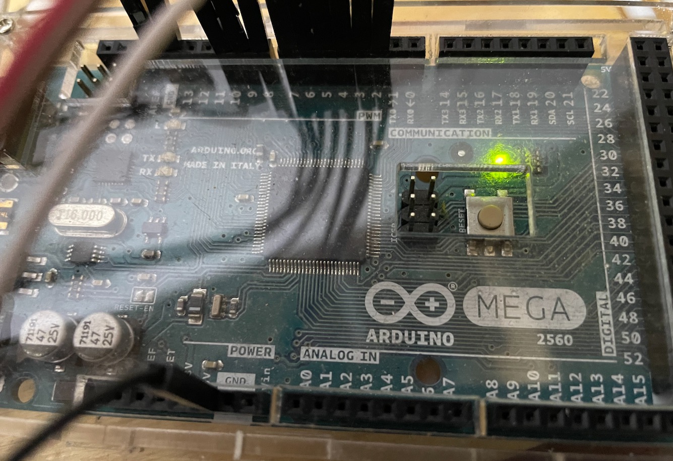
That's the existing Audrino that runs to HS that I'm essentially trying to replicate in HE.
No resistors are used, I've not needed them to date and had no issues as it's such a simple setup I presume.
I hope that makes sense.
K.
I really need to completely understand the wiring before I can assist. Please provide the make and model of the PIR sensors, and a wiring diagram of exactly how everything is wired. Without that drawing, I really cannot help any further. The picture you provided does not really help me to understand the wiring, as it only shows one end of the wiring, but does not show power supplies, the PIR sensors, etc… Knowing the complete wiring diagram, on a single page, with all devices accounted for, is the only way I can fully understand how your existing system is designed. There are multiple ways to wire things up, and thus the code needs to account for your particular use case.
Thanks. Dan but that I don't have and some of those sensors have been there for years, as in over a decade. Some I couldn't even tell you what brand they were let alone get info on them now.
But they are standard alarm PIRs all powered by 12VAC using 2.5-5V tamper and alarm.
So all I have is a common GND for all motion sensors and the + goes to the digital pins on the Arduino, a few are newer Bosch ones that they show wiring for like this:

That one is just a typical example.
On the current setup I have a GND on the Audrino wired to all as the GND/- to all the sensors as it's a common.
The + from each momentary contact goes to the corresponding pin as in, say the bathroom sensor is digital pin 2 so the + for that goes there. The Arduino detects the change and I want to register that as being an open or closed state.
On there NC/NC opens on motion so normally closed.
Wiring-wise, it'd look something like this as it's only using the low switching of the PIR to do this:
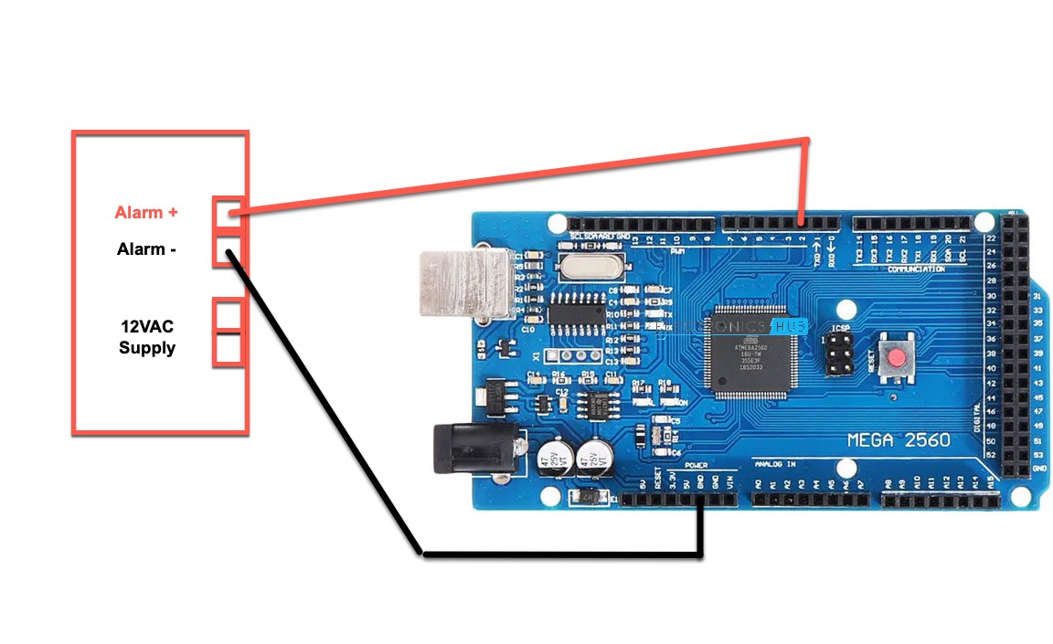
The 12VAC supply to the PIRs is completely separate and unrelated to what I'm doing there.
I hope that makes sense.
K.
Yes, that helps immensely. Based on your diagram, the Arduino is using its Internal-PullUp feature. This is exactly how I have my own wired contact and PIR sensors wired to my microcontroller. I’ll whip up a sketch shortly for you to test with.
Brilliant, thank you.
With a bit of luck I hope to understand that side o things a little better as I reckon it's probably handy to know.
K.
Based on the above image, it does not appear that you are using an Ethernet Shield, at least not one that I can see. There are some RESERVED PINS when an W5x00 series Ethernet shield is used on an Arduino MEGA 2560, and some of your existing wiring conflicts with those reserved pins.
Also, it appears that you only have 9 Digital pins in use, pins 2-10. Is that correct? Do you want all of these to show up in Hubitat as Motion Sensors, correct?
I will need to move your wires to pins 22-30 instead, to avoid the Ethernet Shield.
@kwatt - Here is sketch that should get you going. Please be sure to read the HubDuino README file, as it explains pretty much everything one needs to know. There is an assumption that users of HubDuino are already somewhat familiar/proficient with the Arduino IDE, C/C++ programming, and basic electrical circuitry. So, if you get hung up along the way, please feel free to reach out as the community is very helpful.
Note: There are some lines in this code that only you can properly fill in. They are all marked as needing the user to change them.
//******************************************************************************************
//  File: HubDuino_KennethWatt_EthernetW5x00_MEGA.ino
//  Authors: Dan G Ogorchock & Daniel J Ogorchock (Father and Son)
//
//  Summary:  This Arduino Sketch, along with the ST_Anything library and the revised SmartThings
//            library, demonstrates the ability of one Arduino + Ethernet W5x00 Shield to
//            implement a multi input/output custom device for integration into SmartThings.
//            The ST_Anything library takes care of all of the work to schedule device updates
//            as well as all communications with the Ethernet W5x00 Shield.
//
//            ST_Anything_Multiples implements the following ST Capabilities in multiples of 2 as a demo of what is possible with a single Arduino
//              - 9 x Motion devices (used to detect motion)
//
//            During the development of this re-usable library, it became apparent that the
//            Arduino UNO R3's very limited 2K of SRAM was very limiting in the number of
//            devices that could be implemented simultaneously.  A tremendous amount of effort
//            has gone into reducing the SRAM usage, including siginificant improvements to
//            the SmartThings Arduino library.
//
//            Note: This sketch was fully tested on an Arduino MEGA 2560 using the Ethernet W5x00 Shield.
//
//  Change History:
//
//    Date        Who            What
//    ----        ---            ----
//    2015-01-03  Dan & Daniel   Original Creation
//    2017-02-12  Dan Ogorchock  Revised to use the new SMartThings v2.0 library
//    2017-04-16  Dan Ogorchock  New sketch to demonstrate multiple SmartThings Capabilties of each type
//    2017-04-22  Dan Ogorchock  Added Voltage, Carbon Monoxide, and Alarm with Strobe
//    2017-07-04  Dan Ogorchock  Added MQ-2 based Smoke Detection
//    2022-06-24  Dan Ogorchock  Modified for Kenneth Watt
//
//******************************************************************************************
//******************************************************************************************
// SmartThings Library for Arduino Ethernet W5x00 Shield
//******************************************************************************************
#include <SmartThingsEthernetW5x00.h>    //Library to provide API to the SmartThings Ethernet W5x00 Shield

//******************************************************************************************
// ST_Anything Library
//******************************************************************************************
#include <Constants.h>       //Constants.h is designed to be modified by the end user to adjust behavior of the ST_Anything library
#include <Device.h>          //Generic Device Class, inherited by Sensor and Executor classes
#include <Sensor.h>          //Generic Sensor Class, typically provides data to ST Cloud (e.g. Temperature, Motion, etc...)
#include <Executor.h>        //Generic Executor Class, typically receives data from ST Cloud (e.g. Switch)
#include <InterruptSensor.h> //Generic Interrupt "Sensor" Class, waits for change of state on digital input
#include <PollingSensor.h>   //Generic Polling "Sensor" Class, polls Arduino pins periodically
#include <Everything.h>      //Master Brain of ST_Anything library that ties everything together and performs ST Shield communications

#include <PS_Illuminance.h>  //Implements a Polling Sensor (PS) to measure light levels via a photo resistor on an analog input pin
#include <PS_Voltage.h>      //Implements a Polling Sensor (PS) to measure voltage on an analog input pin
#include <PS_TemperatureHumidity.h>  //Implements a Polling Sensor (PS) to measure Temperature and Humidity via DHT library
#include <PS_Water.h>        //Implements a Polling Sensor (PS) to measure presence of water (i.e. leak detector) on an analog input pin
#include <PS_MQ2_Smoke.h>    //Implements an Polling Sensor (PS) to monitor the status of an analog input pin from a MQ2 sensor
#include <IS_Motion.h>       //Implements an Interrupt Sensor (IS) to detect motion via a PIR sensor on a digital input pin
#include <IS_Contact.h>      //Implements an Interrupt Sensor (IS) to monitor the status of a digital input pin
#include <IS_Smoke.h>        //Implements an Interrupt Sensor (IS) to monitor the status of a digital input pin
#include <IS_CarbonMonoxide.h> //Implements an Interrupt Sensor (IS) to monitor the status of a digital input pin
#include <IS_DoorControl.h>  //Implements an Interrupt Sensor (IS) and Executor to monitor the status of a digital input pin and control a digital output pin
#include <IS_Button.h>       //Implements an Interrupt Sensor (IS) to monitor the status of a digital input pin for button presses
#include <EX_Switch.h>       //Implements an Executor (EX) via a digital output to a relay
#include <EX_Alarm.h>        //Implements Executor (EX)as an Alarm capability with Siren and Strobe via digital outputs to relays
#include <S_TimedRelay.h>    //Implements a Sensor to control a digital output pin with timing/cycle repeat capabilities
#include <EX_Switch_Dim.h>   //Implements an Executor (EX) for a switch (on/off) and pwm output (level) uses 2 digital output pins

//**********************************************************************************************************
//Define which Arduino Pins will be used for each device
//  Notes: Arduino communicates with both the W5x00 and SD card using the SPI bus (through the ICSP header).
//         This is on digital pins 10, 11, 12, and 13 on the Uno and pins 50, 51, and 52 on the Mega.
//         On both boards, pin 10 is used to select the W5x00 and pin 4 for the SD card.
//         These pins cannot be used for general I/O. On the Mega, the hardware SS pin, 53,
//         is not used to select either the W5x00 or the SD card, but it must be kept as an output
//         or the SPI interface won't work.
//         See https://www.arduino.cc/en/Main/ArduinoEthernetShieldV1 for details on the W5x00 Sield
//**********************************************************************************************************
//"RESERVED" pins for W5x00 Ethernet Shield - best to avoid
#define PIN_4_RESERVED            4   //reserved by W5x00 Shield on both UNO and MEGA
#define PIN_1O_RESERVED           10  //reserved by W5x00 Shield on both UNO and MEGA
#define PIN_11_RESERVED           11  //reserved by W5x00 Shield on UNO
#define PIN_12_RESERVED           12  //reserved by W5x00 Shield on UNO
#define PIN_13_RESERVED           13  //reserved by W5x00 Shield on UNO
#define PIN_50_RESERVED           50  //reserved by W5x00 Shield on MEGA
#define PIN_51_RESERVED           51  //reserved by W5x00 Shield on MEGA
#define PIN_52_RESERVED           52  //reserved by W5x00 Shield on MEGA
#define PIN_53_RESERVED           53  //reserved by W5x00 Shield on MEGA


//Analog Pins

//Digital Pins
#define PIN_MOTION_1              22  //Hubitat Capability "Motion Sensor"
#define PIN_MOTION_2              23  //Hubitat Capability "Motion Sensor"
#define PIN_MOTION_3              24  //Hubitat Capability "Motion Sensor"
#define PIN_MOTION_4              25   //Hubitat Capability "Motion Sensor"
#define PIN_MOTION_5              26  //Hubitat Capability "Motion Sensor"
#define PIN_MOTION_6              27  //Hubitat Capability "Motion Sensor"
#define PIN_MOTION_7              28  //Hubitat Capability "Motion Sensor"
#define PIN_MOTION_8              29  //Hubitat Capability "Motion Sensor"
#define PIN_MOTION_9              30  //Hubitat Capability "Motion Sensor"


//******************************************************************************************
//W5x00 Ethernet Shield Information
//******************************************************************************************

//NOTE - If your shield came with a MAC address sticker - please use that MAC address!
byte mac[] = {0x06,0x02,0x03,0x04,0x05,0x06}; //MAC address, leave first octet 0x06, change others to be unique //  <---You must edit this line!

IPAddress ip(192, 168, 1, 226);               //Arduino device IP Address                   //  <---You must edit this line!
IPAddress gateway(192, 168, 1, 1);            //router gateway                              //  <---You must edit this line!
IPAddress subnet(255, 255, 255, 0);           //LAN subnet mask                             //  <---You must edit this line!
IPAddress dnsserver(192, 168, 1, 1);          //DNS server                                  //  <---You must edit this line!
const unsigned int serverPort = 8090;         // port to run the http server on

// Smartthings Hub Information
//IPAddress hubIp(192, 168, 1, 149);  // smartthings hub ip       //  <---You must edit this line!
//const unsigned int hubPort = 39500; // smartthings hub port

// Hubitat Hub Information
IPAddress hubIp(192, 168, 1, 145);    // hubitat hub ip         //  <---You must edit this line!
const unsigned int hubPort = 39501;   // hubitat hub port

//******************************************************************************************
//st::Everything::callOnMsgSend() optional callback routine.  This is a sniffer to monitor
//    data being sent to ST.  This allows a user to act on data changes locally within the
//    Arduino sktech withotu having to rely on the ST Cloud for time-critical tasks.
//******************************************************************************************
void callback(const String &msg)
{
  //Uncomment if it weould be desirable to using this function
  //Serial.print(F("ST_Anything_Miltiples Callback: Sniffed data = "));
  //Serial.println(msg);

  //TODO:  Add local logic here to take action when a device's value/state is changed

  //Masquerade as the ThingShield to send data to the Arduino, as if from the ST Cloud (uncomment and edit following line(s) as you see fit)
  //st::receiveSmartString("Put your command here!");  //use same strings that the Device Handler would send
}

//******************************************************************************************
//Arduino Setup() routine
//******************************************************************************************
void setup()
{
  //******************************************************************************************
  //Declare each Device that is attached to the Arduino
  //  Notes: - For each device, there is typically a corresponding "tile" defined in your
  //           SmartThings Device Hanlder Groovy code, except when using new COMPOSITE Device Handler
  //         - For details on each device's constructor arguments below, please refer to the
  //           corresponding header (.h) and program (.cpp) files.
  //         - The name assigned to each device (1st argument below) must match the Groovy
  //           Device Handler names.  (Note: "temphumid" below is the exception to this rule
  //           as the DHT sensors produce both "temperature" and "humidity".  Data from that
  //           particular sensor is sent to the ST Hub in two separate updates, one for
  //           "temperature" and one for "humidity")
  //         - The new Composite Device Handler is comprised of a Parent DH and various Child
  //           DH's.  The names used below MUST not be changed for the Automatic Creation of
  //           child devices to work properly.  Simply increment the number by +1 for each duplicate
  //           device (e.g. contact1, contact2, contact3, etc...)  You can rename the Child Devices
  //           to match your specific use case in the ST Phone Application.
  //******************************************************************************************
  //Polling Sensors
  //Interrupt Sensors
  static st::IS_Motion              sensor1(F("motion1"), PIN_MOTION_1, HIGH, true, 500);
  static st::IS_Motion              sensor2(F("motion2"), PIN_MOTION_2, HIGH, true, 500);
  static st::IS_Motion              sensor3(F("motion3"), PIN_MOTION_3, HIGH, true, 500);
  static st::IS_Motion              sensor4(F("motion4"), PIN_MOTION_4, HIGH, true, 500);
  static st::IS_Motion              sensor5(F("motion5"), PIN_MOTION_5, HIGH, true, 500);
  static st::IS_Motion              sensor6(F("motion6"), PIN_MOTION_6, HIGH, true, 500);
  static st::IS_Motion              sensor7(F("motion7"), PIN_MOTION_7, HIGH, true, 500);
  static st::IS_Motion              sensor8(F("motion8"), PIN_MOTION_8, HIGH, true, 500);
  static st::IS_Motion              sensor9(F("motion9"), PIN_MOTION_9, HIGH, true, 500);

  //Special sensors/executors (uses portions of both polling and executor classes)

  //Executors

  //*****************************************************************************
  //  Configure debug print output from each main class
  //*****************************************************************************
  st::Everything::debug=true;
  st::Executor::debug=true;
  st::Device::debug=true;
  st::PollingSensor::debug=true;
  st::InterruptSensor::debug=true;

  //*****************************************************************************
  //Initialize the "Everything" Class
  //*****************************************************************************

  //Initialize the optional local callback routine (safe to comment out if not desired)
  st::Everything::callOnMsgSend = callback;

  //Create the SmartThings EthernetW5x00 Communications Object
    //STATIC IP Assignment - Recommended
    st::Everything::SmartThing = new st::SmartThingsEthernetW5x00(mac, ip, gateway, subnet, dnsserver, serverPort, hubIp, hubPort, st::receiveSmartString);

    //DHCP IP Assigment - Must set your router's DHCP server to provice a static IP address for this device's MAC address
    //st::Everything::SmartThing = new st::SmartThingsEthernetW5x00(mac, serverPort, hubIp, hubPort, st::receiveSmartString);

  //Run the Everything class' init() routine which establishes Ethernet communications with the SmartThings Hub
  st::Everything::init();

  //*****************************************************************************
  //Add each sensor to the "Everything" Class
  //*****************************************************************************
  st::Everything::addSensor(&sensor1);
  st::Everything::addSensor(&sensor2);
  st::Everything::addSensor(&sensor3);
  st::Everything::addSensor(&sensor4);
  st::Everything::addSensor(&sensor5);
  st::Everything::addSensor(&sensor6);
  st::Everything::addSensor(&sensor7);
  st::Everything::addSensor(&sensor8);
  st::Everything::addSensor(&sensor9);

  //*****************************************************************************
  //Add each executor to the "Everything" Class
  //*****************************************************************************

  //*****************************************************************************
  //Initialize each of the devices which were added to the Everything Class
  //*****************************************************************************
  st::Everything::initDevices();
}

//******************************************************************************************
//Arduino Loop() routine
//******************************************************************************************
void loop()
{
  //*****************************************************************************
  //Execute the Everything run method which takes care of "Everything"
  //*****************************************************************************
  st::Everything::run();
}
Brilliant, thank you and that gets me started in understanding some of this although I will confess, I'm far from being what I'd say was proficient by any stretch.
Now all I need to do is work out how to download all the libraries as thus far that has me flummoxed, I can get to the code no problem just not download all the .ino files.
K.
Some searching and I got it, just wasn't obvious. 
Now off to play about and try to get it working.
K.
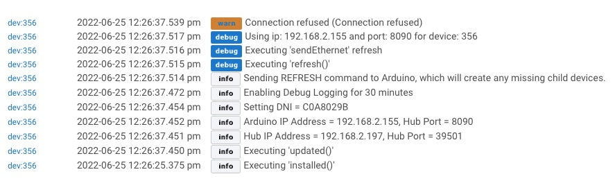
I am sure this is probably a silly thing but on testing, just one thing as once I get one working it's easy to replicate and understand what's going on but I get this:
dev:3542022-06-25 12:08:19.207 pm errorjava.lang.IllegalArgumentException: A device with the same device network ID exists, Please use a different DNI on line 264 (method updated)

I don't understand what it's reporting there.
K.