No Problem. Thanks for the reply. Been checking through everything carefully today but still no joy.
I think I can make this project work by using the Nano 33 IoT with MQTT to Node Red on a PI4b I have running and then into a virtual Voltage Device in Hubitat, but it introduces another step/piece of hardware which I am reluctant to do unless absolutely necessary. Will keep looking at the Hubduino solution for now
1 Like
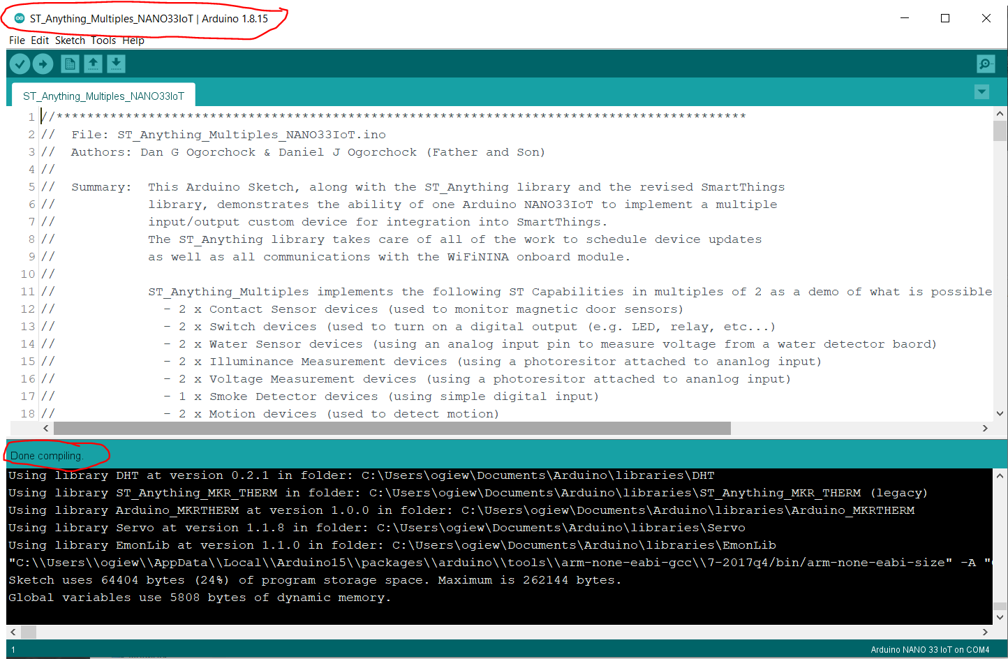
@neil.e.vass - I was able to access a laptop and installed all of the latest ST_Anything libraries and sketches as described in the ReadMe. I was then able to compile the sketch without any errors.
I removed everything Arduino IDE/Sketches and Libraries and removed the folders.
Complete re-download Arduino IDE and files from Github.
Fresh install on my Desktop and my laptop. Both give exactly the same output for me. Which is different from @ogiewon. Also checked the instructions line by line and everything seems to be the same.
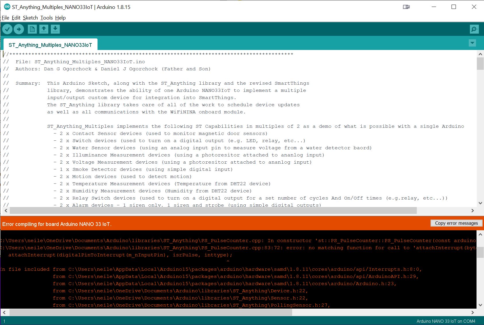
I am really running out of ideas.
Does anyone have any more suggestions!
Thanks
Neil
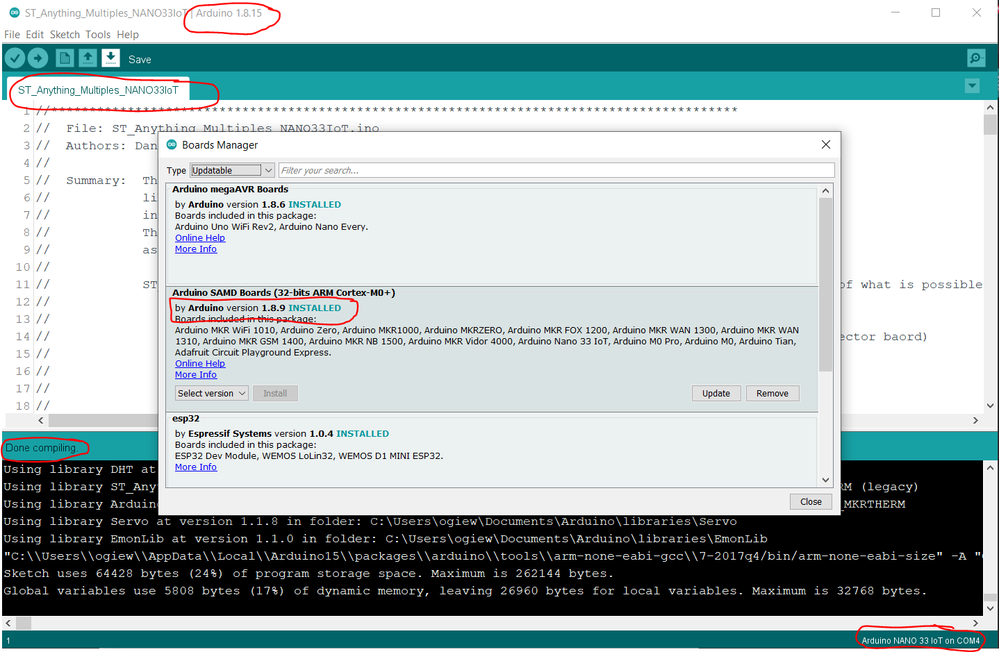
@neil.e.vass - please make sure you're running v1.8.9 of the Arduino SAMD Boards Manager. I have tested newer versions and they cause the issue you're experiencing.
1 Like
Thank you @ogiewon that has killed the compile problem totally.
Now I can spend some time learning and trying to get stuff working on my own.
Thanks again for your help.
Neil
1 Like
Bless you! You solved my problem, too.
1 Like
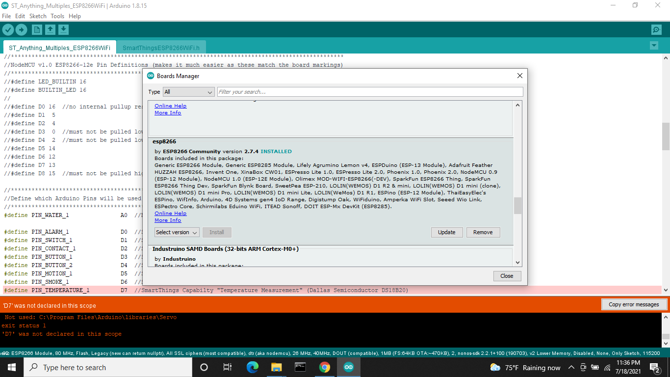
Hello Community, I have an issue that i've not seen before. I'm getting an error message that I hope to paste in here, please see below. I'm working with the ST-ESP8266 Multiples sketch, freshly pulled the full file from the Github page, I edited my IP and WiFi info and went straight to compile. This is what I get. I've even gone as far as to load Arduino 1.8.9 and board manager 2.5.2. Any assistance would be appreciated. I had to reprogram a board last year (I was in win 7 then) and all worked fine. Hope someone else has seen such. Thanks in advance.
Arduino: 1.8.9 (Windows 10), Board: "Generic ESP8266 Module, 80 MHz, Flash, Disabled, All SSL ciphers (most compatible), ck, 26 MHz, 40MHz, DOUT (compatible), 512K (no SPIFFS), 2, nonos-sdk 2.2.1 (legacy), v2 Lower Memory, Disabled, None, Only Sketch, 115200"
C:\Users\Palmetto Chevrolet\Documents\Arduino\Sketches\ST_Anything_Multiples_ESP8266WiFi\ST_Anything_Multiples_ESP8266WiFi.ino: In function 'void setup()':
ST_Anything_Multiples_ESP8266WiFi:92:35: error: 'D7' was not declared in this scope
#define PIN_TEMPERATURE_1 D7 //SmartThings Capabilty "Temperature Measurement" (Dallas Semiconductor DS18B20)
^
C:\Users\Palmetto Chevrolet\Documents\Arduino\Sketches\ST_Anything_Multiples_ESP8266WiFi\ST_Anything_Multiples_ESP8266WiFi.ino:154:71: note: in expansion of macro 'PIN_TEMPERATURE_1'
static st::PS_DS18B20_Temperature sensor2(F("temperature1"), 15, 0, PIN_TEMPERATURE_1, false, 10, 1);
^
ST_Anything_Multiples_ESP8266WiFi:87:35: error: 'D2' was not declared in this scope
#define PIN_CONTACT_1 D2 //SmartThings Capabilty "Contact Sensor"
^
C:\Users\Palmetto Chevrolet\Documents\Arduino\Sketches\ST_Anything_Multiples_ESP8266WiFi\ST_Anything_Multiples_ESP8266WiFi.ino:157:60: note: in expansion of macro 'PIN_CONTACT_1'
static st::IS_Contact sensor3(F("contact1"), PIN_CONTACT_1, LOW, true);
^
ST_Anything_Multiples_ESP8266WiFi:88:35: error: 'D3' was not declared in this scope
#define PIN_BUTTON_1 D3 //SmartThings Capabilty Button / Holdable Button (Normally Open!)
^
C:\Users\Palmetto Chevrolet\Documents\Arduino\Sketches\ST_Anything_Multiples_ESP8266WiFi\ST_Anything_Multiples_ESP8266WiFi.ino:158:59: note: in expansion of macro 'PIN_BUTTON_1'
static st::IS_Button sensor4(F("button1"), PIN_BUTTON_1, 1000, LOW, true, 500);
^
ST_Anything_Multiples_ESP8266WiFi:89:35: error: 'D4' was not declared in this scope
#define PIN_BUTTON_2 D4 //SmartThings Capabilty Button / Holdable Button (Normally Open!)
^
C:\Users\Palmetto Chevrolet\Documents\Arduino\Sketches\ST_Anything_Multiples_ESP8266WiFi\ST_Anything_Multiples_ESP8266WiFi.ino:159:59: note: in expansion of macro 'PIN_BUTTON_2'
static st::IS_Button sensor5(F("button2"), PIN_BUTTON_2, 1000, LOW, true, 500);
^
ST_Anything_Multiples_ESP8266WiFi:90:35: error: 'D5' was not declared in this scope
#define PIN_MOTION_1 D5 //SmartThings Capabilty "Motion Sensor" (HC-SR501 PIR Sensor)
^
C:\Users\Palmetto Chevrolet\Documents\Arduino\Sketches\ST_Anything_Multiples_ESP8266WiFi\ST_Anything_Multiples_ESP8266WiFi.ino:160:59: note: in expansion of macro 'PIN_MOTION_1'
static st::IS_Motion sensor6(F("motion1"), PIN_MOTION_1, HIGH, false);
^
ST_Anything_Multiples_ESP8266WiFi:91:35: error: 'D6' was not declared in this scope
#define PIN_SMOKE_1 D6 //SmartThings Capabilty "Smoke Detector"
^
C:\Users\Palmetto Chevrolet\Documents\Arduino\Sketches\ST_Anything_Multiples_ESP8266WiFi\ST_Anything_Multiples_ESP8266WiFi.ino:161:58: note: in expansion of macro 'PIN_SMOKE_1'
static st::IS_Smoke sensor7(F("smoke1"), PIN_SMOKE_1, HIGH, true, 500);
^
ST_Anything_Multiples_ESP8266WiFi:93:35: error: 'D8' was not declared in this scope
#define PIN_TIMEDRELAY_1 D8 //SmartThings Capability "Relay Switch"
^
C:\Users\Palmetto Chevrolet\Documents\Arduino\Sketches\ST_Anything_Multiples_ESP8266WiFi\ST_Anything_Multiples_ESP8266WiFi.ino:164:64: note: in expansion of macro 'PIN_TIMEDRELAY_1'
static st::S_TimedRelay sensor8(F("relaySwitch1"), PIN_TIMEDRELAY_1, LOW, false, 3000, 0, 1);
^
ST_Anything_Multiples_ESP8266WiFi:85:35: error: 'D0' was not declared in this scope
#define PIN_ALARM_1 D0 //SmartThings Capabilty "Alarm"
^
C:\Users\Palmetto Chevrolet\Documents\Arduino\Sketches\ST_Anything_Multiples_ESP8266WiFi\ST_Anything_Multiples_ESP8266WiFi.ino:167:46: note: in expansion of macro 'PIN_ALARM_1'
static st::EX_Alarm executor1(F("alarm1"), PIN_ALARM_1, LOW, true);
^
ST_Anything_Multiples_ESP8266WiFi:86:35: error: 'D1' was not declared in this scope
#define PIN_SWITCH_1 D1 //SmartThings Capability "Switch"
^
C:\Users\Palmetto Chevrolet\Documents\Arduino\Sketches\ST_Anything_Multiples_ESP8266WiFi\ST_Anything_Multiples_ESP8266WiFi.ino:168:48: note: in expansion of macro 'PIN_SWITCH_1'
static st::EX_Switch executor2(F("switch1"), PIN_SWITCH_1, LOW, true); //Inverted logic for "Active Low" Relay Board
^
Multiple libraries were found for "Servo.h"
Used: C:\Users\Palmetto Chevrolet\AppData\Local\Arduino15\packages\esp8266\hardware\esp8266\2.5.2\libraries\Servo
Not used: C:\Program Files\Arduino\libraries\Servo
exit status 1
'D7' was not declared in this scope
This report would have more information with
"Show verbose output during compilation"
option enabled in File -> Preferences.
The example ESP8266 sketches are designed to be used with the NodeMCU ESP8266 board, not the generic ESP8266. Change the board type and recompile it to see if the errors go away.
Under board manager (obtained from the spark fun page) version 2.7.4 there is no NodeMCU ESP8266. If this is the right board manager.
Hopefully this will help...
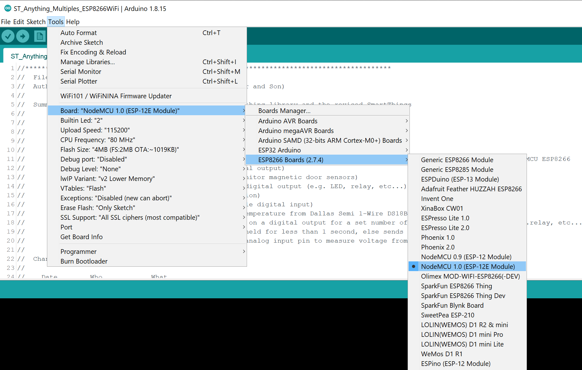
What specific ESP8266 based board are you using? The "D1", "D2", etc... nomenclature is to make it easier to assign pins in the sketch that match the silkscreened pin identifiers found on some boards. The NodeMCU boards have these identifiers on the physical board, but not all boards do. Some use the actual GPIO numbers from the ESP8266 microcontroller itself.
Hi Dan, Went back and tried the basic sketch tonight and it compiled with no errors. I'm not complaining, but I know I tried the ESP-12E module before without success. Either way, it worked, so off to the races. Thanks for the assistance. What I may not have mentioned was that my previous Win7 PC with everything working on it died, and I replaced it with a newer Win 10 machine, so I've had to start over from scratch. LOL
1 Like
This is my first Arduino project. I am attempting to make a water sensor using a M5Stack Atom Lite and a Level Sense LS-2600 leak sensor. The sensor is hooked to ground and the GPIO32 through a spliced grove connector.
When I run my sketch (which has a water sensor and a voltage sensor defined) I see the input value for the water sensor randomly drop to zero and then return to a value above the configured threshold. Additionally I see the reported voltage continuously fluctuating as well. In all cases the sensor is in the same location. When I place the sensor in water the value drops to zero and stays there.
Is this an issue with the sensor I'm using? I would have expected the voltage to stay constant.
Please provide a wiring diagram of how you have hooked the sensor up to the board.
Here is the wiring diagram for the M5Stack Atom Lite and the Level Sense. I am wondering if my issue is related to using a GPIO that supports touch vs one that doesn't.
The Level Sense is connected to the M5Stack Atom Lite via GPIO32 and GRD. I spliced the Grove connector and the Level Sense using UY IDC connectors.
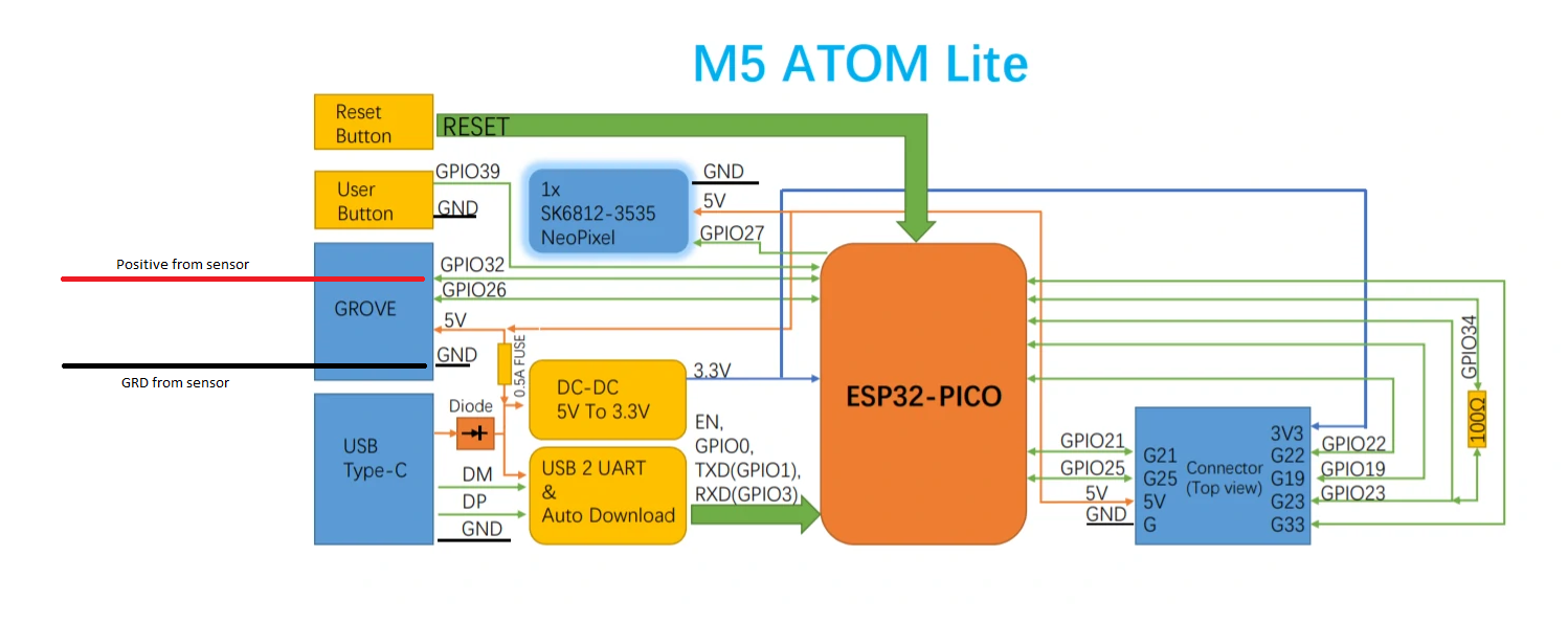
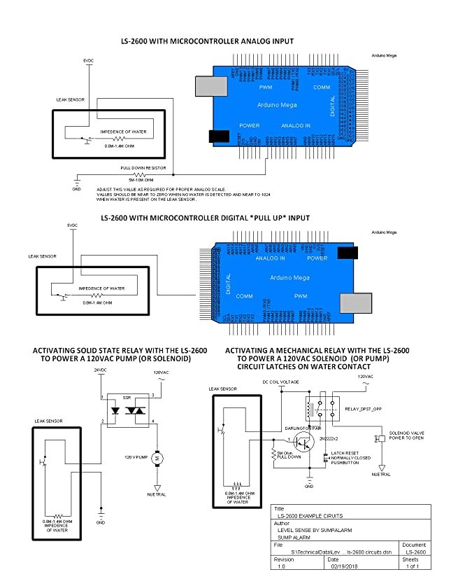
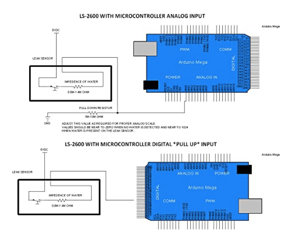
The first diagram shows how I have it wired. On the left side of the diagram I added lines showing how I have the sensor hooked up.
Okay…. Are you using 5VDC or 3.3VDC? Most ESP board’s are rated for 3.3 volts. Use a volt meter to measure the voltage between the GPIO pin and ground, with the sensor dry and wet to see what voltage values you’re getting from the voltage divider setup you’ve implemented.
If you want to use the second wiring diagram, which is much simpler and uses a digital input instead of an analog input, you can use the IS_Water device instead.
//******************************************************************************************
//  File: IS_Water.cpp
//  Authors: Dan G Ogorchock & Daniel J Ogorchock (Father and Son)
//
//  Summary:  IS_Water is a class which implements the Hubitat "Water Sensor" device capability.
//			  It inherits from the st::InterruptSensor class.
//
//			  Create an instance of this class in your sketch's global variable section
//			  For Example:  st::IS_Water sensor6(F("water1"), PIN_WATER, HIGH, true, 500);
//
//			  st::IS_Water() constructor requires the following arguments
//				- String &name - REQUIRED - the name of the object - must match the Groovy ST_Anything DeviceType tile name
//				- byte pin - REQUIRED - the Arduino Pin to be used as a digital input
//				- bool iState - REQUIRED - LOW or HIGH - determines which value indicates the interrupt is true
//				- bool internalPullup - OPTIONAL - true == INTERNAL_PULLUP
//				- long numReqCounts - OPTIONAL - number of counts before changing state of input (prevent false alarms)
//
//  Change History:
//
//    Date        Who            What
//    ----        ---            ----
//    2020-06-30  Dan Ogorchock  Original Creation
//
//
//******************************************************************************************
I have the M5Stack Atom Lite (ESP32 pico) powered via 5VDC (per M5Stack's documentation).
I took the following measurements using my multimeter:
- GRD/GPIO reading (no sensor attached) is ~.9V,
- Dry sensor reading was 1.2V
- Wet sensor reading was ~0.02V
In my sketch I left the following values as is. Do these need to be adjusted based on my numbers above?
analogReadResolution(11);        // Default of 12 is not very linear.  Recommended to use 10 or 11 depending on needed resolution.
analogSetAttenuation(ADC_6db);   // Default is 11db which is very noisy.  Recommended to use 2.5 or 6.
BTW - thanks for taking the time to help. It's really appreciated!
No, you can leave those as-is since the precise voltage reading is not critical to whether or not the sensor is detecting water.
What PS_Water value is being displayed in the Arduino IDE’s Serial Monitor window? This value should change drastically when the sensor goes from dry to wet. You will then need to change the threshold value used in the sketch when the PS_Water device is created.
Make sure you tweak the device settings based on how your sensor behaves, per the documentation below.
//******************************************************************************************
//  File: PS_Water.cpp
//  Authors: Dan G Ogorchock & Daniel J Ogorchock (Father and Son)
//
//  Summary:  PS_Water is a class which implements both the SmartThings "Water Sensor" device capability.
//			  It inherits from the st::PollingSensor class.  The current version uses an analog input to measure the
//			  presence of water using an inexpensive water sensor.
//
//			  Create an instance of this class in your sketch's global variable section
//			  For Example:  st::PS_Water sensor3(F("water1"), 60, 6, PIN_WATER, 200, false);
//
//			  st::PS_Water() constructor requires the following arguments
//				- String &name - REQUIRED - the name of the object - must match the Groovy ST_Anything DeviceType tile name
//				- long interval - REQUIRED - the polling interval in seconds
//				- long offset - REQUIRED - the polling interval offset in seconds - used to prevent all polling sensors from executing at the same time
//				- byte pin - REQUIRED - the Arduino Pin to be used as an analog input
//				- int limit - OPTIONAL - the alarm limit to compare analog pin's reading to, above which the sensor reports "wet" instead of "dry", default = 100
//				- bool invertLogic - OPTIONAL - if set to true, will invert the comparison against target from < to >, default = false
//
//			  This class supports receiving configuration data from the SmartThings cloud via the ST App.  A user preference
//			  can be configured in your phone's ST App, and then the "Configure" tile will send the data for all sensors to
//			  the ST Shield.  For PollingSensors, this data is handled in the beSMart() function.
//
//			  TODO:  Determine a method to persist the ST Cloud's Polling Interval data

