[Release] HubDuino v1.1.9 - Hubitat to Arduino / ESP8266 / ESP32 / ThingShield Integration (ST_Anything)

@ogiewon While waiting for a couple of MAX31855 thermocouples, I thought I would try using a MAX6675 thermocouple board that I already have. I don't think they use the same libraries as the 31855. What modifications would I need to make to add the 6675 library?

Just to expand on what Bruce has pointed out....."supported" on the platform level means that you do not need to define the attributes and commands for that capability when developing a driver. For example, if you define a driver as supporting the switch capability, you don't have to also list commands for on and off or the attribute "switch". You can just skip over that and define the methods for on and off. If you add switch level capability, the driver doesn't have to list the command setLevel or the attribute "level" under it's metadata, you can just use the method setLevel and the attribute "level" in your driver because they come from the capability Switch Level.

And from an app perspective, if you pick a device that supports the switchLevel capability, you can assume that the device supports the setLevel command, because that is part of that capability.

If we didn't have the switchLevel capability, can you imagine how hard it would be to write an app for the platform? If every developer got to choose what commands to use for different things it would be chaos. You would never be able to do anything if you always had to check to see what command that driver used to set the level.

A capability is just a shorthand that includes a bunch of commands and attributes. And "support" for that capability from the platform level means that those commands and attributes have been defined in the platform. Nothing more. Every app has it's own set of limitations as far as supported commands, capabilities and attributes and nothing says that an app has to support all the capabilities the platform does. Nor would we want them to.

Also Pressure isn't the only capability that isn't listed in Rule Machine. There are several others. But they are all so esoteric that, IMHO, they don't warrant the time to integrate them, especially now that custom attribute triggers allow you to trigger off of literally anything, even attributes that are not part of a supported capability. The custom attributes give you more flexibility than just limiting the app to supported capabilities. I'm sure if more folks start using barometric pressure as a trigger and everyone start clamoring for it, Bruce would revisit that choice. But you are literally the first person I've seen try and use barometric pressure as a trigger in a rule. You're the Jackie Robinson of Barometric Pressure Rules! :wink:

1 Like

I very much appreciate your response @Ryan780. It helps me to understand things a lot better. Knowing all this now, I've probably confused things a bit. I was using RM capabilities as an example, albeit I now see a bad one, thinking the capability should show in all places if it showed in one. I mentioned the built in app Link to Hub also and that is really what I wanted to do with this. I wanted to send this info to my other hub but I see I'm not going to be able to do this. I can still reprogram and move this device to the other hub and do what I need that way I think. I am running the InfluxDB Logger (that has support for pressure devices) on my second hub to send data to Influxdb. I have no devices connected directly to this hub.

Edit: Just to explain better what I'm doing, this device is essentially a little weather station I have out on the front of my shed. It provides temperature, humidity, barometric pressure and illuminance data that I have on a dashboard. So far I'm only using illuminance to trigger anything. When I got to experimenting with InfluxDB and Grafana, I wanted to chart this data but the device is on my primary hub. The pressure data is the only part I can't push to the second hub with Link to Hub that is running the InfluxDB Logger app.

Hi @zarthan. In order to add support for a different thermocouple board, I would recommend you start with a copy of the PS_AdafruitThermocouple.h and .cpp files. Rename the copies to include the MAX6675 name. Then, within both files, change everything to use the MAX6675 name as well. Include the correct Adafruit library for the MAX6675, and change any calls to use that new library's calls.

This is basically how I add support for any new device. Start with something that is close to the new device, copy its .h and .cpp files, then hack away to make the new files work for the new device.

1 Like

Thanks. I did give that a try and I think I am close. I am not at that computer but if I remember I got a type declaration missing.

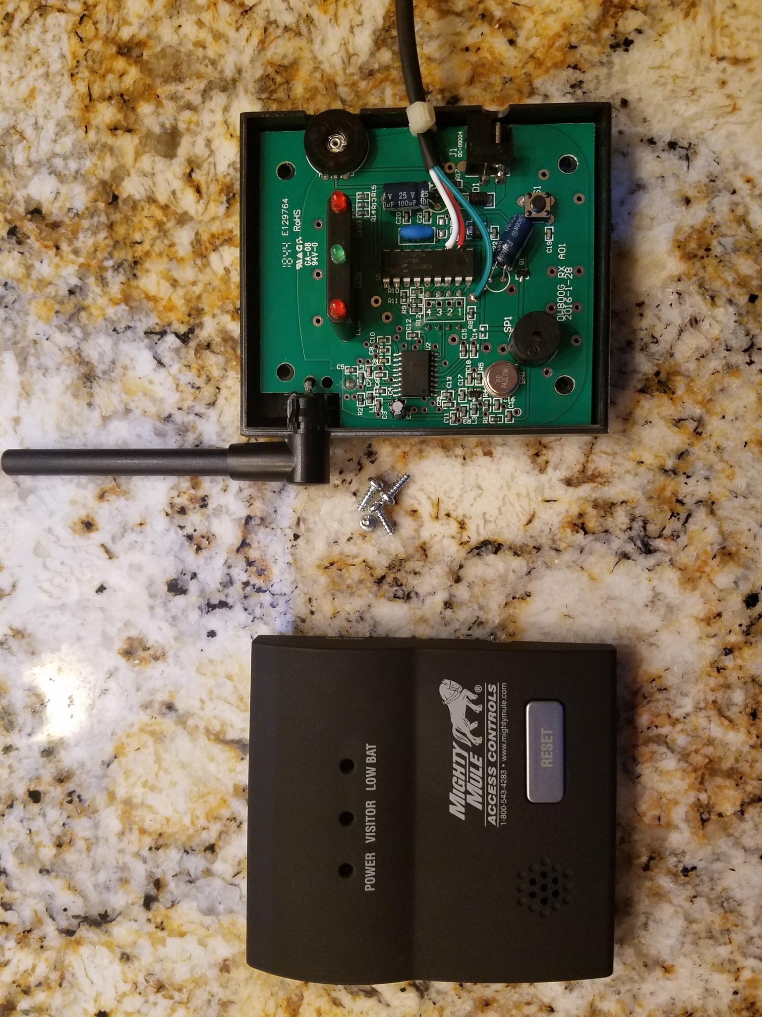
Wanted to share my recent project with HubDuino! I have a Mighty Mule driveway alert, but needed to integrate it into HE. Searched the forums and found this:

After watching that vid, I opened mine up and did some testing. Found that pin 11 is for the battery low indicator, and pin 12 is for Visitor. It is TTL output (5v). I soldered on a 3-pin plug and drilled a small hole in the case to pass out the side.

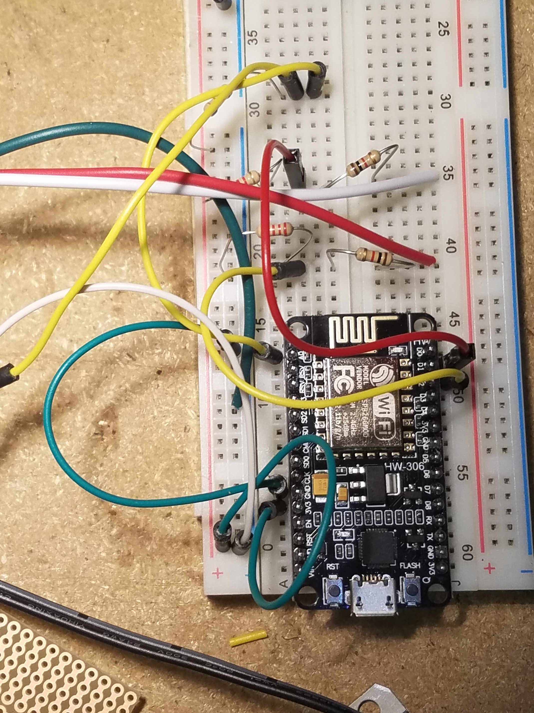
I used a simple voltage divider to connect these to D1 and D2 of a NodeMCU. (Gnd -- 2,2kR -- Input Pin -- 1kR -- TTL output)

I made D1 and D2 Contact switches. I am also using A0 for a 10k thermistor that is going in my freezer.

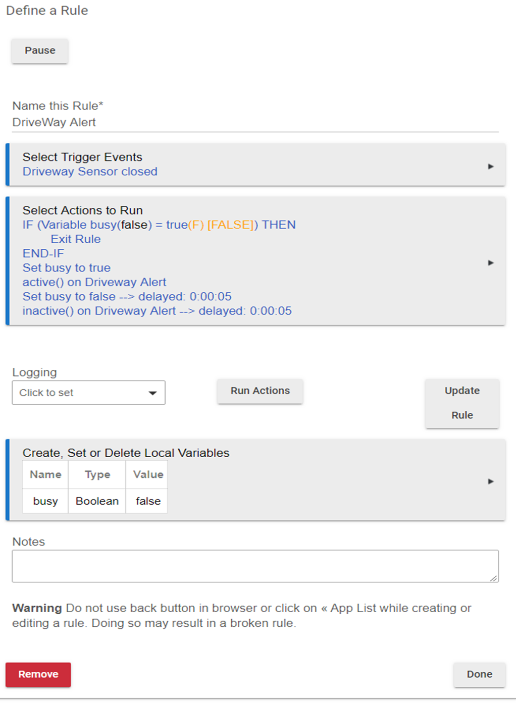
I created a virtual Motion Sensor and a Rule to trigger it:

Next step is to get audio announcements integrated into my ancient NuTone intercom. My plan is to use another HubDuino and this tied to the Tape input: Adafruit Audio FX Mini Sound Board - WAV/OGG Trigger - 2MB Flash : ID 2342 : $14.95 : Adafruit Industries, Unique & fun DIY electronics and kits

4 Likes

I've been recommending someone do this forever! Glad to see it actually works. :slight_smile: Now I'll have something to link when the question comes up again. Nice job!!!

3 Likes

Hey there, so I am really happy with this project! I setup my own NodeMCU with 4 DHT22/11 sensors + a contact sensor (via reed relay) to sense when my large custom 3D printer pauses (sensed via a 12v LED run that turns on when the printer hits an error state or pauses for some reason - this trips the reed relay and in turn the contact sensor). The sensors are reading temps/humidity levels in the filament storage containers, and other areas of the printer.

It works great, but the next step I want to do is leverage the temp readings toward potentially controlling fans via PWM (via a fan driver that takes the PWM signal from the ESP), Adding a pot/Angle sensor (to tweak the fan trigger threshold) and a I2C LCD to display current status. From my testing I think I can get all this to work on a single NodeMCU (using virtually every pin).

I suck at writing code in Arduino... so I am going to take a while to do that it seems as nothing works as I hoped in a first attempt :slight_smile: I need to do a lot more reading to figure out how to get the sensor data in a format that is usable for anything else and then learn all the other bits!

2 Likes

I am not a coder, and 6 weeks ago I thought Arduino was a village in Italy. Not. Anyway, bought a Uno kit, along with a NodeMCU ESP8266, and other bits and pieces, so getting along in figuring this all out.

I would appreciate some guidance:
What would be the easiest way to send 1 of 5 non-PWM values to my sketch from HE? I plan to use the values as the index to an array, which contains step position values for a stepper motor. I did look at the Servo and Dimmer drivers/sketches but they both seem to use the switchLevel capability to send a PWM value to a pin (along with a lot of other capabilities that I would not use), so modifying those would be an immense undertaking (for me at least).

Background:
My use case is to tilt (not raise) 2" blind slats using a stepper motor. Now I have read a lot of the posts in this thread re the pros/cons of steppers vs servos for blind tilting, with one of the biggest cons against steppers being the need to implement limit switches. I am using 28BYJ-48 steppers in bipolar mode, and driving them with A4988s. Note though that this post is not to rehash the merits of each solution, but my own preference is steppers (at least for now).

I found a very easy implementation of using one Hall affect sensor to set the Home Position upon restart/startup, using Accelstepper.h. Once the HP is set, further stepper movements are determined by an input of the new target positions, which I set in the array - and hence the need to be able to send the index value from HE. The step position limits are set in the code, so once the HP is set there is no need for any physical limit switches. I also added in Sleep for the driver when not moving.

I tested my sketch with index inputs from the Serial Monitor, and it does exactly what I want. In my case I do not need a slider, since I find that 90% of the time I open/close blinds to certain positions - and hence the 5 position values in the array would meet my needs without having the capability to fine tune positions.

Again, any suggestions would be appreciated.

As an FYI, this is the post that started the above for me. I replaced the mechanical limit switch with a Hall effect sensor, and as mentioned also added in the array that contains the position step values:

I think the biggest argument in favor of using servo's instead of steppers is that there's already a Hubduino Library for servos and there isn't one for steppers. So, one would have to be written to implement the functionality that you mention.

But how are you going to hit those positions without the accuracy of a servo? Unless you home your stepper before every movement, you're not going to get enough accuracy.

I get that, and hence my question if there is a way for me to get 5 non-PWM values from HE to my sketch?

I can modify (or wreck) stuff as needed if I get some pointers, and would not necessarily look to others to develop it. Having said that, a substantial part of this community is all about learning new things, and thinking outside the box (yourself included . . . :slight_smile: ). As I had mentioned, one of the biggest pushbacks against steppers was the need for limit switches - and hence the acceptance of servos. I now have the Hall effect sensor in place that takes care of the need for limit switches, and if I can make this work it could very well be useful to someone else for whatever purpose . . . .

In my case high precision is moot. With 2048 steps/revolution, if the motor was off by 1 step, that equates to 0.17 degree. Even if it was off by 10 steps (1.7 degrees) it would not be visible to the naked eye in tilted blinds.

However, steppers are used in most (if not all) high-precision applications that we use every day - for example an inkjet printer sitting on my desk, DVD/CD players, etc. Then there are CNC machines in manufacturing, where 100% accuracy is required. In addition, the use of Hall effect sensors is used widely in industry.

I'm sorry, I don't follow. Why would you have to send all 5 values at once? Why couldn't you just send each value when it was needed? Also, noting says that you have to use PMW values. You could send a value of anything you like. You might find it easier to use the ESP8266 wifi example sketch rather than the ST_Anything example. This shows you how to implement communication between the hub and the board to pass any type of data you want. It can be found in the same repo in the following directory.
\Arduino\libraries\SmartThings\examples\SmartThings_On_Off_LED_ESP8266WiFi

Then you could send over any value you wanted and do anything you wanted with it.

My bad. As I wrote in my original post - only 1 of 5 values will be sent.

I had only looked at the Switch and Dimmer sketches/drivers, and in those they send PWM values. I will take a look at that sketch you sent. Thnx.

Thanks for the above.

Ok so I have the OTA set up, and I can "send data" from the HubDuino Parent Device page to the ESP8266 - to toggle the LED on/off.

How would I send the data from a Tile or Rule and not the Device page? I assume that would only be possible once a Child device is created on the Arduino and Replicated on the HE Parent, correct?

They are not PWM values, they are percentages. But you can translate that into any number you want. I don't know why you think a percentage is a PWM value.

I'm sorry, I thought, based on your insistence about steppers, that you had more experience with Arduino and Hubitat.. I don't think you're going to be able to do what you're trying to do. I suggest switching to a servo.

Just found Hubduino and it is awesome...

Having trouble with the ST_Anything pulseCounter library. Causes the Esp8266 to go into a reboot loop. Rst2 code reboot.

Trying to use this to measure pulses from my electricity meter.

Definately the pulse part having issues. If I comment out
st::PS_PulseCounter sensor3(F("power1"), 60, 5, PIN_PULSE, FALLING, INPUT_PULLUP, 1.0, 0);
It doesn’t crash.

Any ideas appreciated.
Cheers Chris

Hmmmm... I don't recall any other user reporting that particular issue. I haven't fired up that code in quite some time. I originally wrote the pulse counter library for a user who wanted to monitor water flow through a sensor that generated a pulse train. Your use case makes perfect sense as well.

Does the board crash even if no field wiring is attached? If you have just the USB connection attached, does it still crash? Also, does it crash immediately? I am trying to recall if I added any watchdog support to the ESP8266 code to try to recover in the event of a lockup that some experienced after their hubs locked up... If that is in there still, I wonder if there is any chance it is causing the issue? I'll need to fire up a system when I have some free time.

@Ryan780 wrote "I suggest switching to a servo"

Tried it last night, and got it up and running in 30 mins, so servos is the way to go now. Will keep on tinkering with the steppers . . .

I re-visited Amazon. My previous search for "high torque" servos showed them to be running $16-$20 per servo (which influenced my earlier decision to use steppers), but last night found 4 x 995s for less than $20. Reading through the numerous posts re servos, it would seem that the 995s would be fine for 5 foot 2" faux wood blinds. Any thoughts?

Then, I noticed something else:
I plan to use the servos connected to the tilt shafts on the left and right sides of blinds. Using a Dimmer or Level slider with a range from 0 - 100 would "close" the blind to 0 at the bottom tilt position, and "open" the blind to the top tilt position at 100. This flips to 100 for open at the bottom, and 0 for close at the top since the direction of shaft travel flips from CCW to CW depending on the location (L or R) of the servo on the shaft.

Is there a way to "invert" the Level depending on L or R installation, so that 0 would always be at the bottom?

This is the servo that I am using for my long, 8' 2" faux wood blinds.

https://www.amazon.com/gp/product/B073F92G2S

Yes, it's a little more expensive but it works flawlessly with the newest servo library for Hubduino. Also, it requires a 6-7v power supply, not 5. So, that can be a factor as well.

I read that earlier you were using 996r. If you don't mind me asking, how did those work out and why did you change