I feel like I'm having an issue when I use the "contact" example of the esp8266. Like it's firing continuosly when the level is low. I have REED switches for contact closure and they are closed when the magnet (door) is closed. But when I hook them up, my HPE seems to go out to lunch. How are contact closures working in HPE? are they edge or level interrupt triggered, and if level, do they go infinite loop on me if the level is met? Sorry, just confused at the moment why hooking up my reed switches makes everything break when it was fine without those on there.
Which GPIO pin and what type of board are you using? Near the end of my ReadMe, I details which ESP8266 pins are able to be used without issue.
It sounds like you have a floating input.
They are not using real HW interrupts at all. Every time through the Arduino loop() routine, all Interrupt Sensors have their digital input pins read and compared against the previous value. If there is a change detected, then a message is sent to the hub to indicate the new status.
There is a number of loop() iterations option when defining an Interrupt Sensor, like the IS_Contact device. This is to act as a debounce to prevent false triggers.
The IS_Contact examples in the ST_Anything_Multiples... sketches use the Internal_PullUp feature of the digital input pins. It should be noted that not all GPIO pins support Internal_PullUp and thus the user should either change to use a pin that does, or supply their own External PullUp resistor. If using an External PullUp, please be sure to adjust the IS_Contact declaration as such in the setup() portion of the sketch.
1 Like
I still haven't debugged my gpio contact issue. My 3 relays work great without my reed contact's connected, but things get odd if they are. I'll have to put the serial logger on and see if there is something being printed.
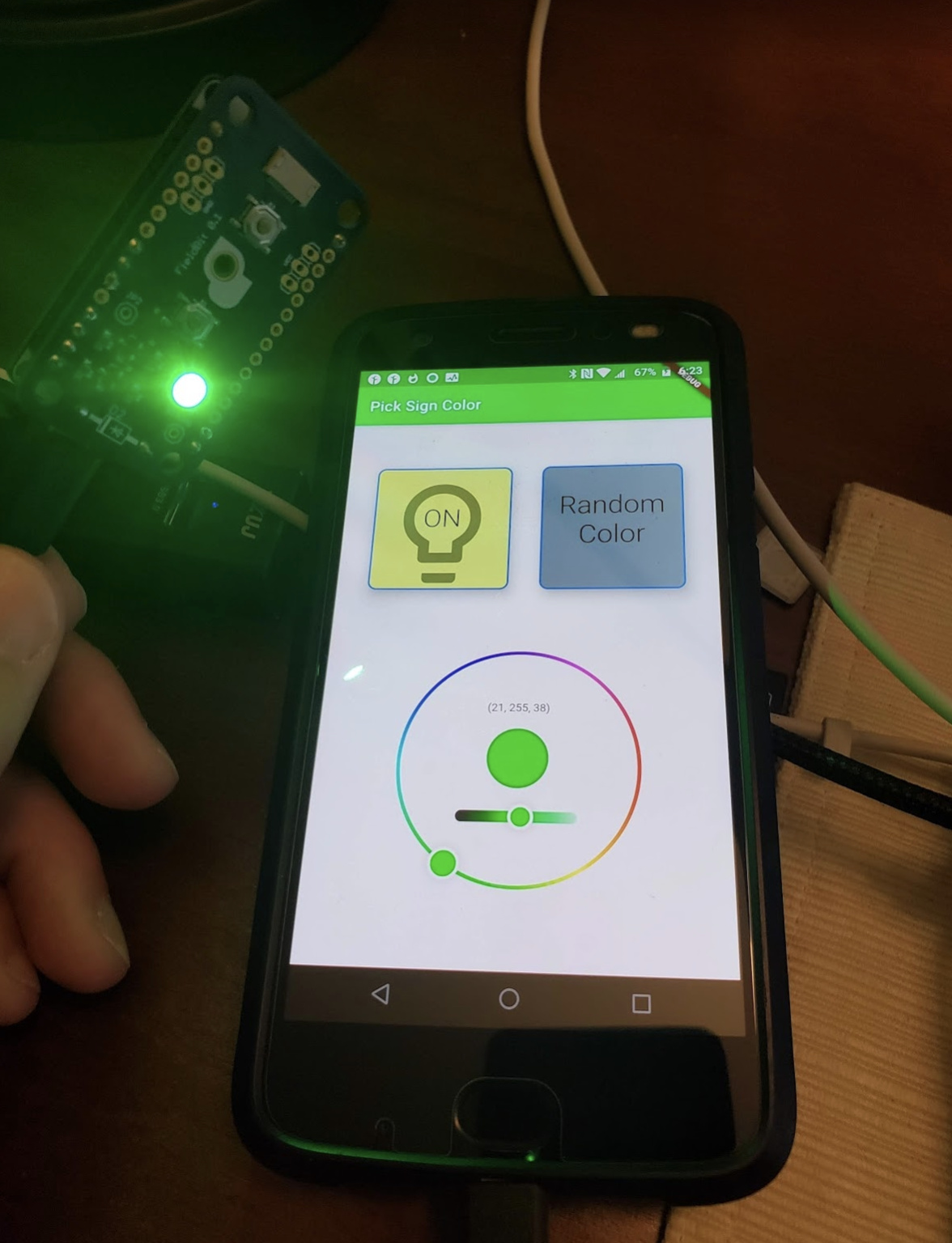
Anyway, sounds like @bravenel is updating the maker api to take rgb which will be nice for neopixel! Makes it simple/consistent to just send the values that neopixel uses directly.
Here's a quick app that works well with the new neopixel example and maker api.
1 Like
Hi Dan (and all), reposting and editing this from the ST_Anything thread, as it better fits here. I’m wondering if it is possible to combine multiple relays (and possibly sensors) into a single device. I have 2 use cases, both for a new house designed and wired especially for Hubduino (so the stakes are high for me)...
Wired Window Shades: Each shade uses two switches (or Timed Relays), one for Up and one for Down. Instead of showing up as two different switches, it would of course be fantastic if it were to be interpreted by Hubitat as a single Window Shade with “Up” and “Down” functions instead of two “On” and “Off” switches. There have been previous requests for blinds, which are more complex. Shades just use a tubular motor on two different relays, so I'm hoping this is something that could be implemented without any need of testing actual shades. Basically the individual relays would be programmed like a Timed Relay, with enough time to fully lower or raise a given shade (user could test and enter the correct timing for each shade). That would be enough to really make a difference for me, but a bonus would be to have intermediate positions, which would be based on time, either calculated as a percentage of total raise/lower time, or (far easier from a programming standpoint, I'm sure) extra virtual buttons that could be coded in the Arduino sketch with custom times. 12V tubular motors are very inexpensive, so I can see this being really useful for people if implemented.
Latching relays: Latching/bistable relays have 2 coils in them: one that is pulsed to turn on, and one that is pulsed to turn off. Right now the only way to do this from Hubduino is to treat them as two different switches. Once again, that’s very confusing on the hub interface side of things. It would be much better if they showed up as a single switch, where toggling it to the “On” state sent a momentary activation to one relay/coil and toggling it to the “Off” state sent a momentary activation to the second relay/coil. Because DPDT latching relays could also be used to send back confirmation to the Arduino of the state it’s in (which can currently be done by adding a third device in Hubduino, a contact sensor), it would be even better if it were possible to incorporate a contact sensor into a single device as the status reporter. This would open up a whole new world of possibilities for many people, as latching relays have many advantages over momentary relays for home automation purposes, when it is a question of occasionally flipping the state of something (like turning off an appliance when out of town) rather than activating it for a short time (like a light switch). Latching relays require no power to maintain, maintain their state even if power or internet is interrupted, Hubitat goes down, etc. Because almost no Z-wave/Zigbee/wifi devices have this capability, Hubduino could be the go-to solution if implemented.
Basically, both of these applications would use very similar logic on both the Arduino and Hubitat side of things, so I'm wondering if it might be possible to implement them both in one fell swoop! Both would be easily extensible to many more applications as well. Basically, I'm asking about/for a new class of composite devices in Hubduino that would greatly extend its abilities. Thank you in advance for considering this!
@zachhorton - Are you an Arduino programmer? If so, I believe both of your requests could be completely implemented on the Arduino side of things. These are somewhat complex devices compared to the traditional ones, but not too hard to build. They just need to be thoroughly thought out and designed well so as to appear fairly seamless to the end-user on Hubitat.
The second one seems simpler to me. How long would the momentary pulse need to be to turn on/off the relays? We'd basically need a device that uses 1 digital input to indicate the current state of the 'switch' as either 'on' or 'off', and two momentary digital outputs - one for ON and one for OFF signals to the latching relay.
I have a similar situation. I am using Hubduino to detect the signals from a thermostat. There are three separate signals (heat call, cooling call, and fan call). In my current implementation, they come into Hubitat as three contact sensor devices. I would like them to show up as a single device which implements the ThermostatOperatingState capability. In another thread, I asked for advice about combining these signals on the groovy end. That seems possible, though not super-elegant, by writing an App which reacts to the contact sensor events to update a virtual ThermostatOperatingState device. I considered trying to do that by modifying the sketch code, but that seemed too daunting. The number of possibilities is way to vast to request Dan to implement each of them. However, if Dan produced one sample application that combines multiple sensed quantities into a higher level sensor device and/or combines multiple actuators into a higher level actuator device, mortals might be able to build on that.
The IS_DoorControl.cpp device is a good example of combining a Digital Input and a Digital Output in a single device.
This is a little bit tricky... Are you simply monitoring these signals? If so, a truly custom sketch might be the best solution, as ST_Anything (Arduino code) was not designed to allow a single ST_Anything 'Device' to handle multiple digital inputs. A custom sketch would be fairly easy to create that uses the "SmartThings..." communications library instead of the full ST_Anything library.
I just remembered a device that basically works this way already. I created it for a user to be able to open and close a valve, using two timed relay outputs in a single device. It could be tweaked easily to allow it to behave as an Open/Close Window Shade device without much effort.
//******************************************************************************************
//  File: EX_TimedRelayPair.cpp
//  Authors: Dan G Ogorchock
//
//  Summary:  EX_TimedRelayPair is a class which implements the "Valve" device capability, where output1 opens a valve, and
//            output2 closes a valve.  It features optional automatic-turn-off time delay times for for both outputs.
//
//			  It inherits from the st::Executor class
//
//			  Create an instance of this class in your sketch's global variable section
//			  For Example:  st::EX_TimedRelayPair executor1(F("valve1"), PIN_RELAY1, PIN_RELAY2, LOW, true, 1000, 1000);
//
//			  st::EX_TimedRelayPair() constructor requires the following arguments
//				- String &name - REQUIRED - the name of the object - must match the Groovy ST_Anything DeviceType tile name
//				- byte pinOutput1 - REQUIRED - the Arduino Pin to be used as a digital output
//				- byte pinOutput2 - REQUIRED - the Arduino Pin to be used as a digital output
//				- bool startingState - REQUIRED - the value desired for the initial state of the switch.  LOW = "closed", HIGH = "open"
//				- bool invertLogic - REQUIRED - determines whether the Arduino Digital Output should use inverted logic (e.g. active high versus active low relays)
//				- long Output1Time - REQUIRED - the number of milliseconds to keep the output1 on, DEFAULTS to 1000 milliseconds, 0 = will stay on
//				- long Output2Time - REQUIRED - the number of milliseconds to keep the output2 on, DEFAULTS to 1000 milliseconds, 0 = will stay on
I'm not an Arduino programmer, unfortunately. I do have a pretty good high-level understanding of how these things work, though. I think a safe pulse for latching relays would be 250ms.
Yes, this is exactly what I was thinking. The difficulty, it seems to me, is in combining those multiple inputs and outputs so they look like one device to Hubitat.
This looks like it could be used for window shades, definitely! Is there a way to code this so Hubitat reads it as a shade and not a valve? And is there a way to add, say, two more controls in the Hubitat device (besides OPEN and CLOSE) with custom timings? On the Arduino side it would just be something like Output1Time2 and Output2Time2 variables. It would activate the same output, with a different time.
I am creating a "Child Window Shade" driver right now. Should have something to test shortly.
Now we're getting a little greedy, eh? ![]()
Just kidding. Let's 'walk' before we 'run' and see how that goes.
1 Like
The 'trick' to simplifying this is to handle it all in the Arduino code, not on the Hubitat side. From Hubitat's perspective, it is just an on/off switch.
Oh, thank you so much!
Ha ha, true! Just getting this to work with OPEN and CLOSE would definitely be a great starting point.
And with regard to the latching relay,
That makes perfect sense. I guess it then becomes an issue of tying the sensor input pin to reported state, output pin for coil 1 to ON, and output pin for coil 2 to OFF.
I'm getting excited! It was the existence of ST_Anything that caused me to ambitiously wire up my new house, during construction, for mostly wired rather than wireless devices. The more complex devices are the wired window shades and the latching relays, so you are really making my dream come true on this project. Thank you!
1 Like
As far as the Arduino is concerned, I am simply monitoring the signals. My Hubitat App acts on the signals using other actuators. I have thought about moving some of the logic from Hubitat to Arduino in the future, but have made no attempt to implement that yet.
You are intimately familiar with what is in these libraries, so I appreciate your advice. I will take some time to look at what is in the SmartThings... library and try to come up with something. Hopefully I will come up with workng code. More likely what I will come up with is another list of questions.
1 Like
OK, I think I have something for you to try. I am guessing/hoping that you're using an ESP8266 based microcontroller. I created an new example sketch named "ST_Anything_WindowShade_ESP8266WiFi.ino", along with a revised "HubDuino Parent Ethernet" driver and a new "Child Window Shade" driver.
All of these are available in my GitHub repository. Update your Hubitat hub to use the new Parent driver, add the new Child driver, and load up the sketch in the Arduino IDE. You can tweak the 'open time' and the 'close time' in the sketch to experiment.
Have fun and let me know how it goes.
Note: The updated Parent device also has some improvements in how it detects whether or not a microcontroller is 'present' or 'not present'. Once you update it, please be sure to go into each of your other HubDuino devices and click SAVE under the user preferences to make sure the new presence logic is configured correctly.
Sorry, I should have specified that I'm using a Mega with 5100 shield...
Hi Dan, I played around with this and think that I have it setup correctly in my Arduino sketch. I can't test the Window Shades device type at the moment because I only have an ST hub available. I'll be at the location with Hubitat next week and will test then.
Latched Relay: I have successfully tested TimedRelayPair as a valve device, and it works great for a latched relay! I think that the next step is to get that working as a switch instead of a valve. Since both ST and HE understand switches, that's something I can test right away, if you have the opportunity to do it. As mentioned previously, it would also be fantastic to have the option to use an input (contact sensor) to report the state of the switch, though I imagine others would like to also retain the option of doing that with the current method (which is correctly working, but doesn't actually know what the state is downstream of the Arduino).
Thanks again!
I have created a new HubDuino device called 'IS_LatchingRelaySwitch'. I have just added the .h and .cpp files to my GitHub repository, along with an example sketch called 'ST_Anything_LatchingRelaySwitch_ESP8266WiFi.ino'
Have fun! Let me know how the testing goes.
It works perfectly! It pulses the two relays correctly, and at least in ST, it will not return an "on" state if it doesn't get its digital input, or an "off" state if it is present. This is exactly how it should operate. (This is probably obvious, but the reason reporting a latching relay's state through a separate input is important is unlike a regular momentary relay, the state of a latching relay does not depend on the current state of the Arduino's output pins, and thus it is possible for the device and Arduino to fall out of sync. I tested this by altering the input state without pulsing the relay, and the correct state is instantly reported. In critical applications where you need to know from a distance whether something is really on or not, this is extremely helpful! Thank you so much for this!
1 Like
Glad to hear it is working as designed. Have fun!

