Shut down the hub and unplug for 30 seconds before plugging back in.
Could try to test with a system driver if one is available and it keeps having issues.
Shut down the hub and unplug for 30 seconds before plugging back in.
Could try to test with a system driver if one is available and it keeps having issues.
Thanks, the shutdown and power removal worked. Errors are gone and the implant is operating as expected. FYI, I'm using christi999's FGBS-22 driver. Guessing the way we have to include the implant with the default system driver, then switch, and clean-up, may have confused the hub. Also, the hub has been up for a while.
Oh I just realized this is a thread FOR the custom driver, so obviously you are using this one. Sorry @christi999 was not implying this driver was the issue, but I have seen where people just find old unmaintained drivers searching on google and they may or may not work well.
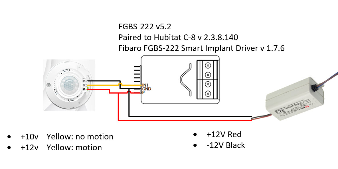
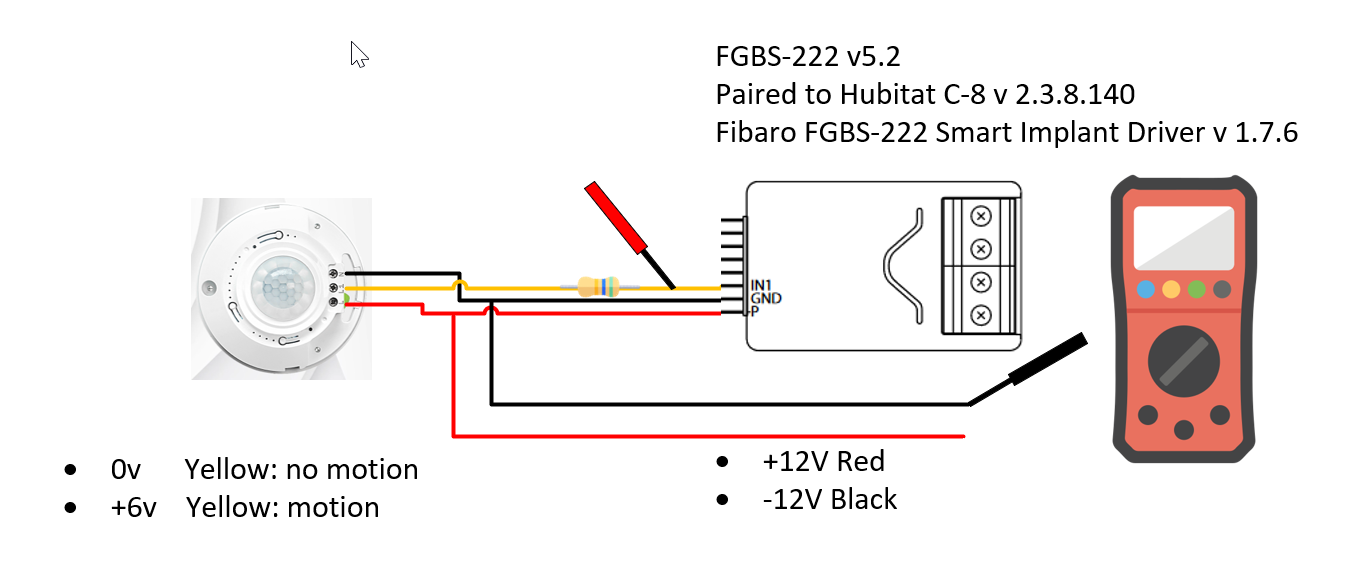
Hi - looking for help setting up what will become a 'wired' motion detector for soffit lights around the perimeter of a house. For this I'm using a Fibaro Smart Implant FGBS-222 v5.2 powered with a 12v transformer. The general idea is that when the soffit lights go on as scheduled, the 12v circuit will be powered and the 12v PIR would activate. Movement would then trigger the Fibaro to trigger the hubitat sequence to brighten the lights via a separate dimmer controller.
The smart implant is installed as a device on a Hubitat Elevation C8 v2.3.8.140 and is using the Fibaro FGBS-222 Smart Implant Driver v 1.7.6 via the Package Manager
I've wired the Smart Implant and the PIR to receive signals as switch 1, noting that when there is no movement the Yellow signal wire indicates 10v, while when there is movement it goes to 12v
I'm currently at a loss on how to configure the implant and switches such that it can recognize the signal into something actionable by the implant.
Any information you can share or point me to would be really appreciated!
The implant is limited to 10V input so you would have to reduce the 12V voltage somehow. I don't know what type of output you have on your PIR so I will have to guess here. I found a match for the picture you provide but the L/N lines take 120V.... That sensor basically connects The L line to the L2 line when there is movements (relay or electronics, I don't know), powering the L2 line with 120V up to 5A. Without movement you get 10V but I don't know what circuit is behind that.
From memory, the implant has an input resistance of about 100K. So, using a 100K resistor in series with your yellow line should reduce the voltage the implant sees by half (5V and 6V). You would then configure IN1 as an analog input without pull-up and set the "minimal change to report" and "periodical reports" to get reports when the voltage change. You could then write rules to trigger on the voltage changes.
Periodical reports are at most every minutes so probably not fast enough for your application, I would disable them. With minimal change to report, the implant doesn't always report very promptly...I don't know if it will be reliable/fast enough.
You could always use polling using an app or rules, at the expense of hub and z-wave network load....
An overall better approach however (something I would do) is to connect your yellow line to a relay (through some simple circuit) and connect the relay contacts between IN1 and GND. That way you could configure IN1 as an alarm input and get an instantaneous and reliable report from the implant whenever the PIR is triggered. I actually did something like that recently for a water rope sensor.
OK, I found the same PIR sensor in the 12V/24V DC version...
So seeing how this sensor works ("The built-in magnetic latching relay offers better performance compared to a traditional relay"), the best approach is probably to use a relay as mentioned in my previous post. Not sure why you get 10V when the sensor is OFF however..
Just connect the coil side of the 12V relay to the PIR middle connector and ground and connect the NO contact side of the relay to the IN1 implant input and ground.
If it was me, I would probably open the thing up and see if the relay inside the PIR could be used instead of adding an external relay. Basically you just want a contact that goes ON and OFF, without the 12V...
OK thanks for the additional info. Not sure why I was getting 10v as well because when I checked it again, prepared to use the resister it was 0v when the sensor is off and ~2v when on.
this is the link to the PIR Amazon.ca
I purchased a few different 12v PIRs to see which one I preferred. This one is makes a loud switching noise when it detects movement. I'll open it up as you suggested and see if I can forgo a the external relay. I'll post results in a few days.
Hi all!
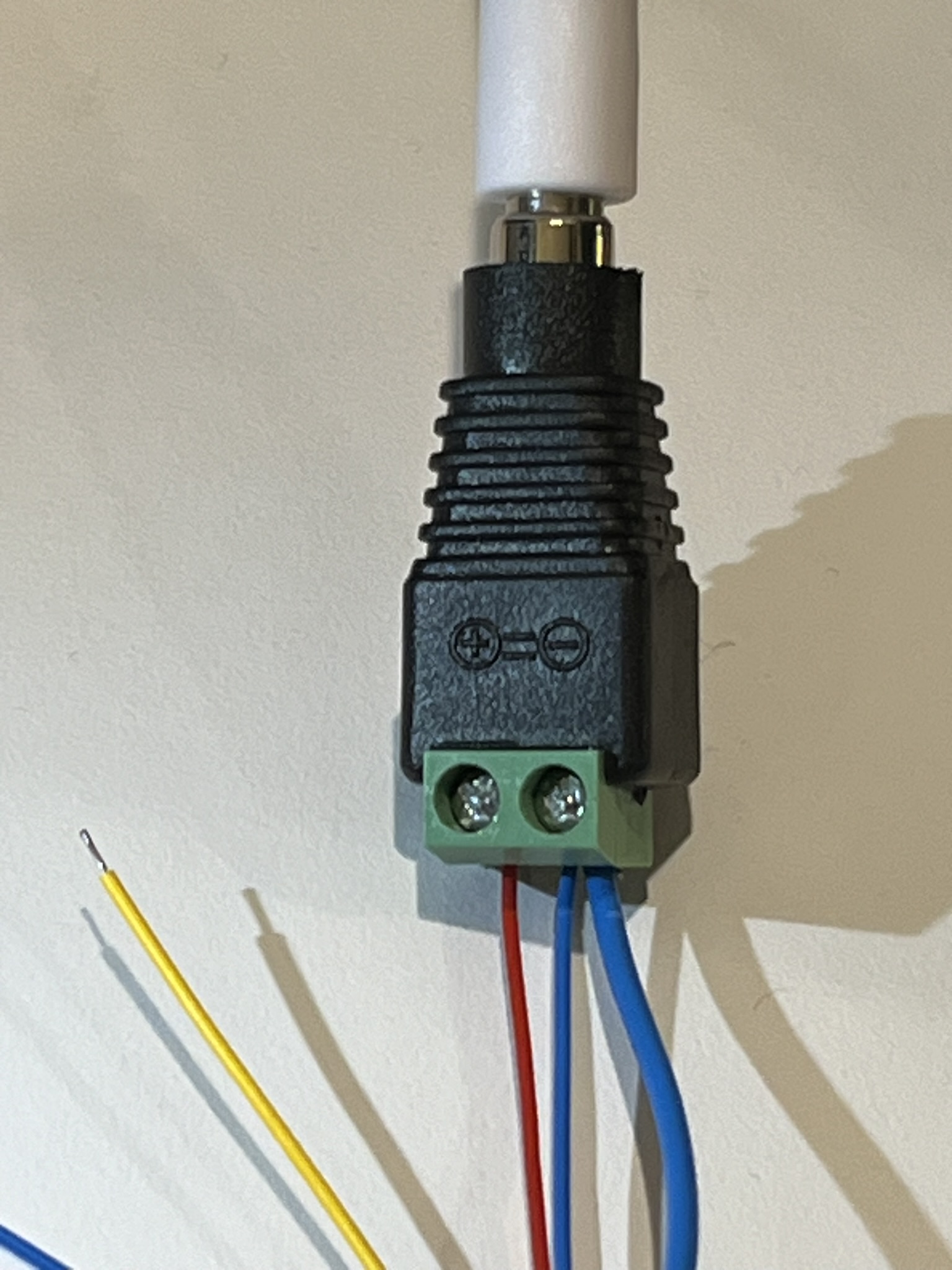
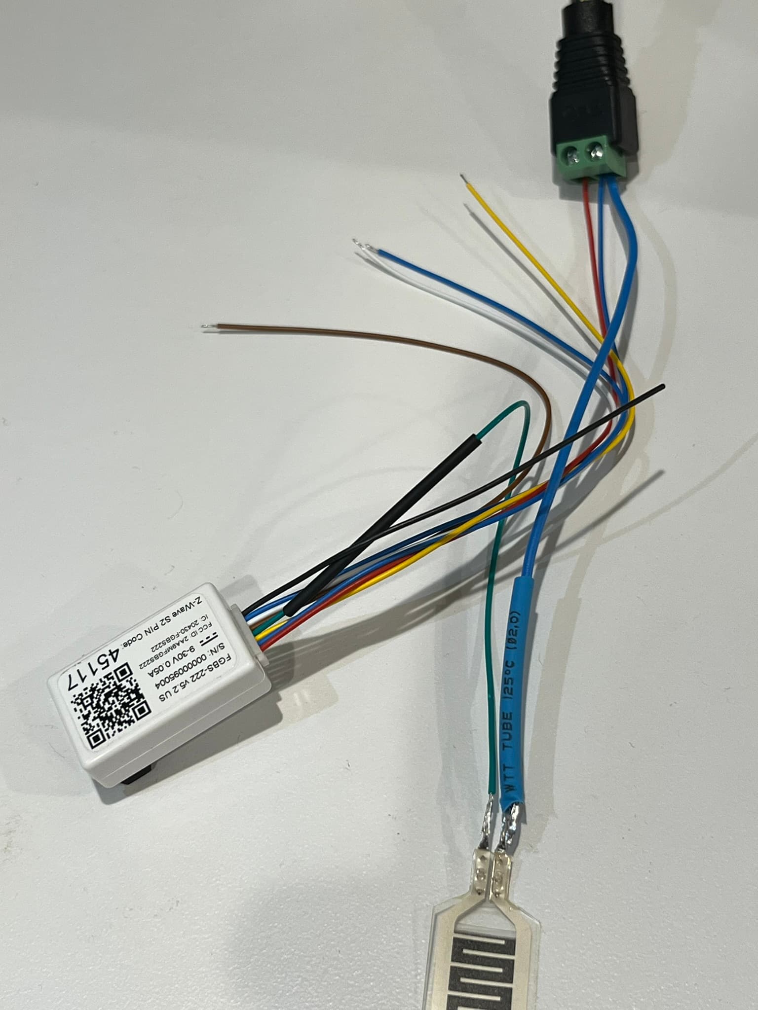
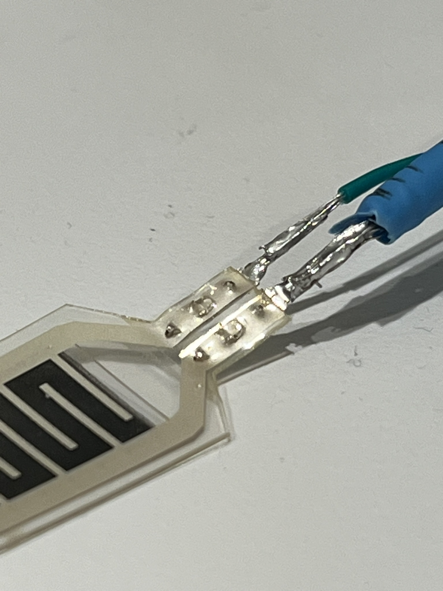
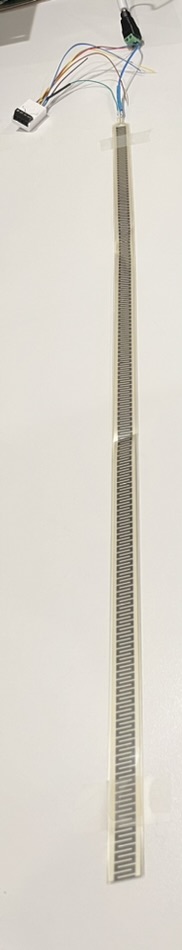
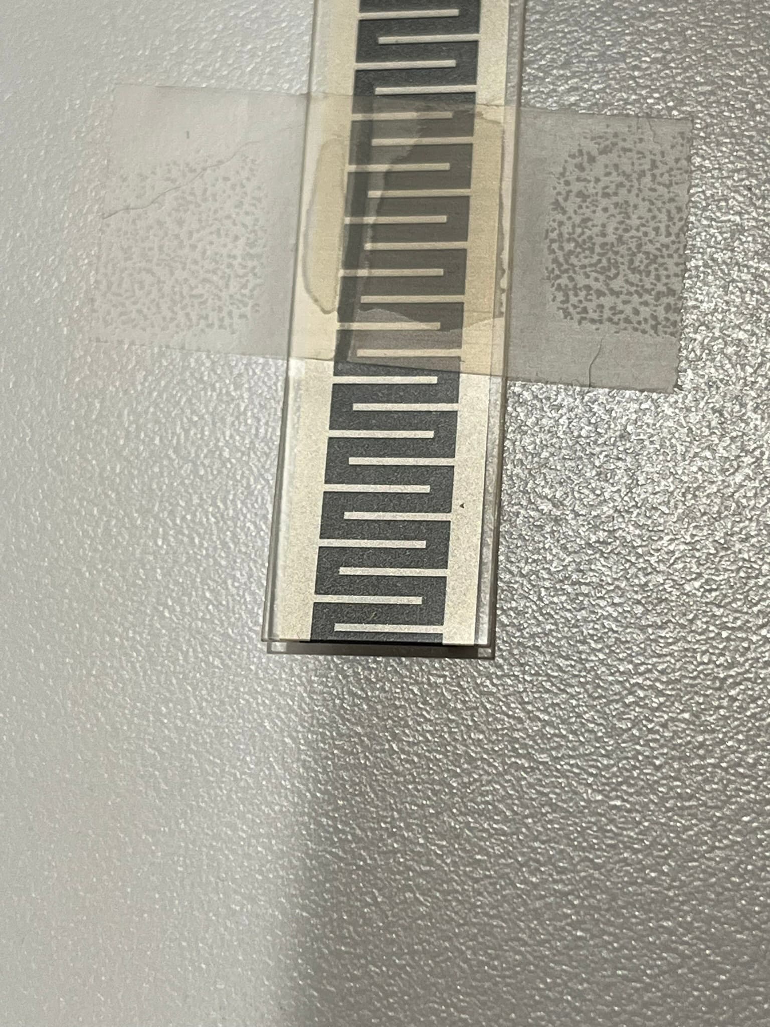
I'm trying to use this Fibaro implant to monitor this analog(?) 'Walfront (mfr) Thin Film Force Sensor Module Flex Resistance-Type Pressure Sensor Resistor SF15-600 10kg 600mm' to detect presence in various scenarios:
NOTE: I simply added the sensor and used Hubitat's built-in 'Fibaro Smart Implant' device setup.. is that different from the drivers that are the basis of this [RELEASE] page? Should I be starting by installing these 5 drivers or can I use the Hubitat defaults?
This is out of my depth, so I've tagged uncertain terms with "(?)" after them.
Safety is of utmost importance, then functionality.
Could you tell me if I've wired this up right?
I assumed from the manual that connection diagram 'E' would apply as the sensor only has two leads (?), but nothing shows up in the logs pictured below:
I'm told analog pressure sensors change resistance based on voltage, so I should measure the difference between input and output voltage and relate it to something (pressure change on the sensor from a person's bodyweight for sort of binary on/off reading).
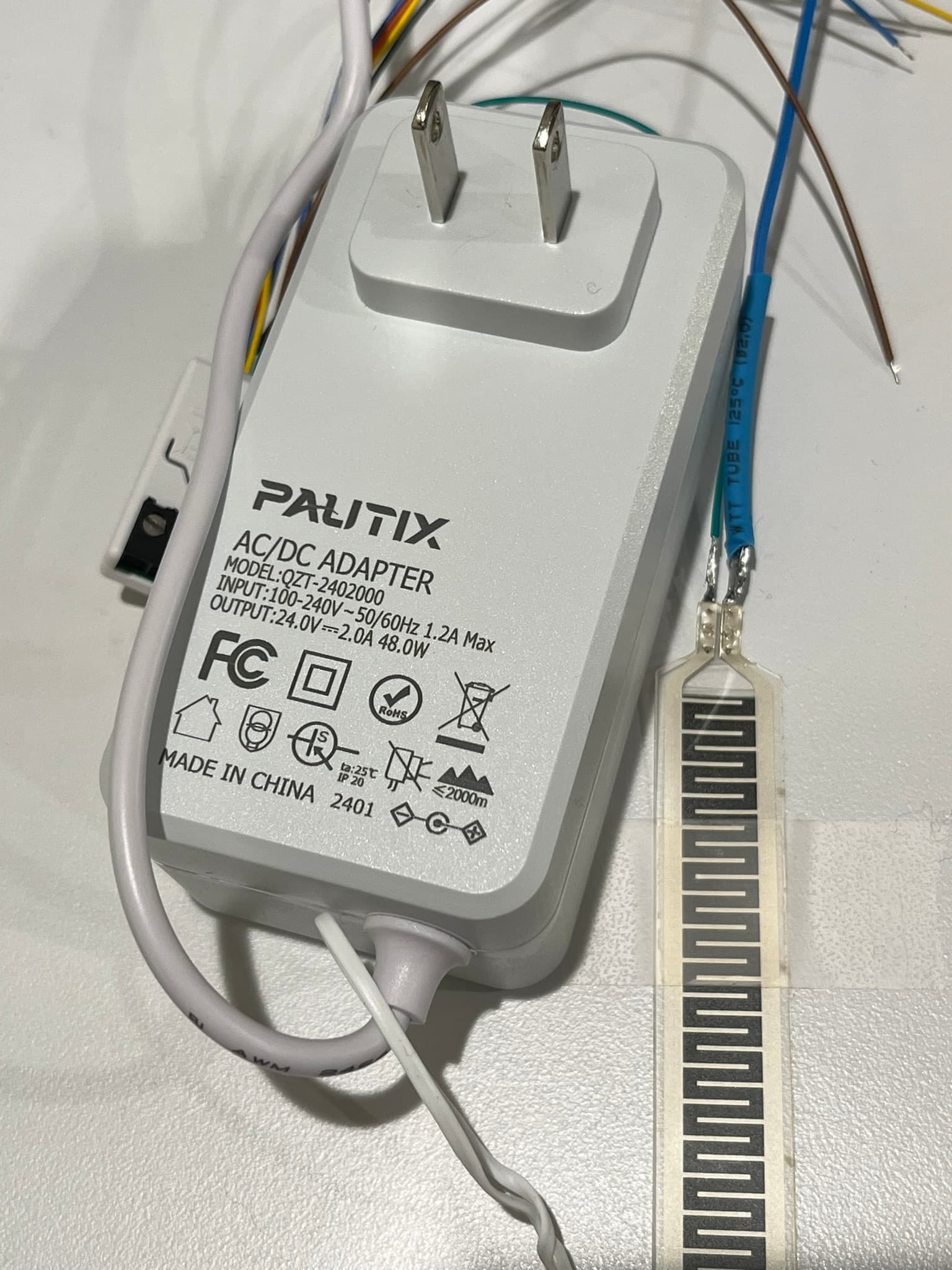
Therefore, I assume I should be sending power to the sensor and measuring the output.. should I connect the thick blue wire from the pressure sensor to the positive (+) port(?) on the barrel adapter from the power source? I don't see that configuration in the manual so I'm worried about safety.. they show a ground out from the device in both analog diagrams 'D' and 'E'.
What should I change - parts used, wiring setup, drivers, device preferences, other programming?
Thanks in advance for helping me learn about this without burning down my place!! ![]()
This thread is for a custom driver I wrote for the implant. I recommend you use my driver to get access to all configuration parameters. The hubitat package manager is the simplest way to install the files.
Figure "E" is more for an active device that sends a 0-10V signal to the implant input. In your case you just have a variable resistor. I can see 3 options here
The thin film sensor goes to zero resistance when activated. In that case you would configure input 2 as an alarm with notification. The connections you are showing should work fine for that case and you will get automatic messages from the implant when the connection state changes. You can test it by shorting the two thin film sensor leads together, if everything is setup right, you should get an alarm message from the implant. You can then test the thin film sensor and see if it generates an alarm, if not then you will most likely need option 2) or 3).
The thin film sensor doesn't go to zero resistance. In that case you can configure input 2 as an analog input with internal pull-up using the connections you are showing. You will not get readings unless you poll the implant manually (go to the child device and "refresh" or automatically using an app or a rule...). You will get a voltage between 0 and 10V. This might or might not work nicely depending on the thin film resistor value.
The thin film sensor doesn't go to zero resistance. In that case you can configure input 2 as an analog input without internal pull-up but you need to supply the 24V voltage to the sensor through a resistor. We can discuss it in more details if you go that way. This also allows you to add a voltage comparator and connect it to input 1 to also get the benefit of the alarm mode in addition to measuring voltage on input 2....
The 24V supply you are using looks fine (overkill really).
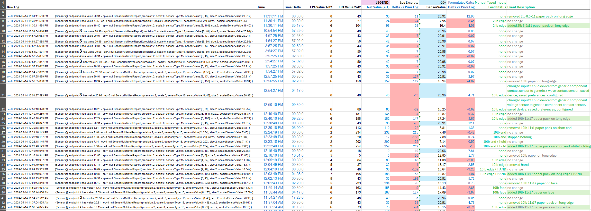
To my surprise, after testing option 2 above, I see that the implant reports voltages proportionally to the supply voltage even if the manual states 0-10V (although in one example they state "The 12V supply is required for these type of sensors"). For instance, it reports 17.4V with a 19.88V supply and nothing connected to it. The input is configured as analog with internal pull-up. The manual doesn't say anything about using the implant in this manner....
In any case, option 2 in my previous post would probably work fine in your case, you would get approximately something like this for a 24V supply using internal pull-up:
  Sensor             Implant
resistance       reported voltage

   10M                 21.0V
   1M                  20.2V
   100K                17.9V
   10K                  8.4V
   1K                   1.3V
   100                 0.14V
   10                  0.01V
Many thanks! I will try out your drivers, appreciate the contribution to the community & reply to my post.
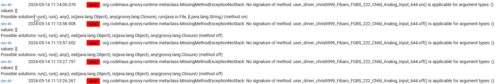
I've made some progress but having issues with my setup/configuration of the implant. The PIR is behaving as it should, signalling @ 6v to the implant once a resister is added.
The only driver settings I've changed were to configure IN1 as an analog input without internal pull-up. I haven't got far enough to set the "minimal change to report" and "periodical reports" to get reports when the voltage change, because when I look in the logs I'm seeing these errors:
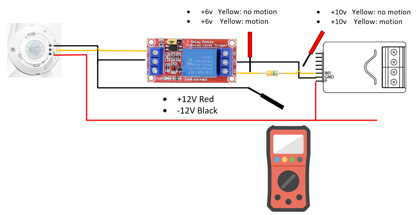
I did open the PIR up as suggested, there appears to be a relay, but its contacts etc weren't evident to a dabbler like me. So I added a 12v relay configured like this which I am sure is incorrect because its giving the same reading whether the PIR is triggered or not
I got the same error when sending an "on" or "off" command to the analog sensor child device using a rule. Although I have added a "switch" capability to that device, sending an "on" or "off command to it doesn't make sense. These errors should be corrected (are you sending ON/OFF to it?) but will not affect anything else. ON/OFF commands can only be sent to the output child devices.
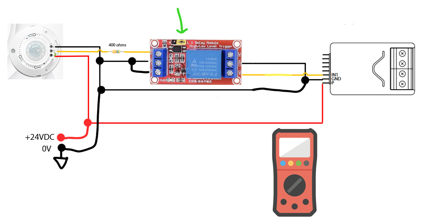
If you are going to use a relay then remove the resistor. To test if the relay is triggered by the PIR, just measure the resistance between NO and COM, it should go from infinite to 0 when the PIR is activated. This should be done without the implant connected to it. Once you know the relay is triggered correctly, reconnect it to the implant, without the resistor, and configure the input as an alarm. You will get an alarm message whenever the PIR changes state. You can then use the "digital input" child device to trigger rules, etc.
l just noticed that your picture is showing a 24V transformer, not 12V as you indicated, which is it? Your picture also indicate "+12V RED" "-12V Black". That would make sense if you had a +/-12V DC supply with a ground reference point but this is just a 24VDC transformer without a center tap, so really 24V with the black lead being ground (0V) ? Am I missing something?
If your relay module is rated for 12V it might get damaged by 24V unless you use a resistor to lower the current going through it when using 24V.
[EDIT] The relay in the picture is rated for a maximum of about 14.4V and has a coil resistance of 400 ohms. You would need to put a resistor of about 400ohms between the yellow wire and the DC+ input of the relay module.
Also, in this picture, I assume the black wire on the left is also connected to the black wire on the right or else the implant gets no ground and therefore no power.
Another thing... I realized that you are using a relay module, not a relay. In that case, you need something connected to the "IN" pin to trigger the relay or nothing will happen. I think (verify with the module documentation) that you could change the yellow jumper position at the top (currently on H , move it one pin, to the L) to trigger the relay on low voltage instead of high and then just connect the "IN" to ground (black wire). That way, whenever the relay is powered (PIR activated), the relay will trigger.
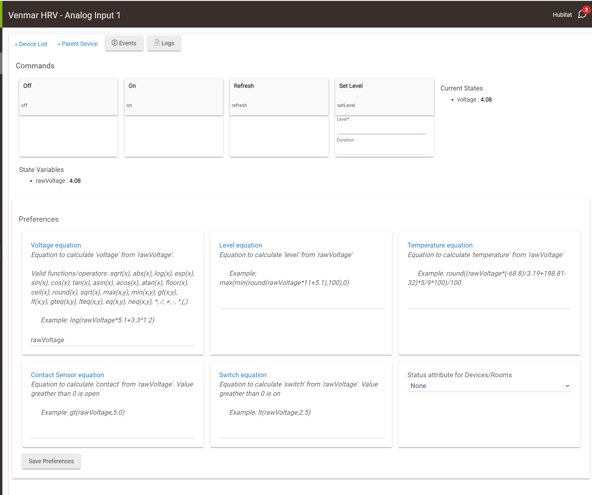
I installed the drivers, saved, configured, etc.
TL;DR: for Option 2, how do you suggest refreshing or using an app or a rule to pull (poll?) the voltage reading given it is reporting only in the logs as noted below in bold?
Do I have the child device type correct as 'Generic Component Voltage Sensor'?
DETAILS:
As for the options you suggested:
I don't think the sensor will go to zero resistance as it's rated for 10 kg and I'll set lighter things on there that should activate the rule.
I tried this, went to the child device to 'refresh' and did not see any voltage readout in the device info under 'current state', nor in the logs:
dev:2212024-05-14 11:16:45.115 PMerrororg.codehaus.groovy.runtime.metaclass.MissingMethodExceptionNoStack: No signature of method: user_driver_christi999_Fibaro_FGBS_222_Smart_Implant_680.componentRefresh() is applicable for argument types: (com.hubitat.app.DeviceWrapper) values: [Living Room Changing Mat Pressure Sensor Analog In 2] (method componentRefresh)
However, I do get this output in the logs when loading/unloading the sensor:
dev:2212024-05-14 08:57:25.768 PMdebug{Sensor @ endpoint 4 has value 20.91 - ep=4 null SensorMultilevelReport(precision:2, scale:0, sensorType:15, sensorValue:[8, 43], size:2, scaledSensorValue:20.91) }
dev:2212024-05-14 08:54:27.921 PMdebug{Sensor @ endpoint 3 has value 20.98 - ep=3 null SensorMultilevelReport(precision:2, scale:0, sensorType:15, sensorValue:[8, 50], size:2, scaledSensorValue:20.98) }
The device reported from 'endpoint 4' exclusively except when I set the IN2 child device to 'generic component contact sensor' instead of 'generic component voltage sensor', then it reported from 'endpoint 4' and 'endpoint 3', every 2 hours, respectively - about 57 minutes apart from each-other.
Here is the parent device configuration report, if it helps:
dev:2212024-05-14 11:07:40.250 PMdebug{ConfigurationReport ConfigurationReport(parameterNumber: 68, size: 2, configurationValue: [0, 0], scaledConfigurationValue: 0)}
dev:2212024-05-14 11:07:39.248 PMdebug{ConfigurationReport ConfigurationReport(parameterNumber: 67, size: 2, configurationValue: [0, 5], scaledConfigurationValue: 5)}
dev:2212024-05-14 11:07:38.262 PMwarnParameter 66 has value 3600 after trying to set it to 1800
dev:2212024-05-14 11:07:38.245 PMdebug{ConfigurationReport ConfigurationReport(parameterNumber: 66, size: 2, configurationValue: [14, 16], scaledConfigurationValue: 3600)}
dev:2212024-05-14 11:07:37.262 PMwarnParameter 65 has value 5 after trying to set it to 9
dev:2212024-05-14 11:07:37.245 PMdebug{ConfigurationReport ConfigurationReport(parameterNumber: 65, size: 2, configurationValue: [0, 5], scaledConfigurationValue: 5)}
dev:2212024-05-14 11:07:36.261 PMwarnParameter 64 has value 3600 after trying to set it to 10
dev:2212024-05-14 11:07:36.243 PMdebug{ConfigurationReport ConfigurationReport(parameterNumber: 64, size: 2, configurationValue: [14, 16], scaledConfigurationValue: 3600)}
dev:2212024-05-14 11:07:35.239 PMdebug{ConfigurationReport ConfigurationReport(parameterNumber: 63, size: 1, configurationValue: [5], scaledConfigurationValue: 5)}
dev:2212024-05-14 11:07:34.240 PMdebug{ConfigurationReport ConfigurationReport(parameterNumber: 157, size: 2, configurationValue: [0, 200], scaledConfigurationValue: 200)}
dev:2212024-05-14 11:07:33.238 PMdebug{ConfigurationReport ConfigurationReport(parameterNumber: 156, size: 2, configurationValue: [0, 0], scaledConfigurationValue: 0)}
dev:2212024-05-14 11:07:32.248 PMdebug{ConfigurationReport ConfigurationReport(parameterNumber: 155, size: 1, configurationValue: [0], scaledConfigurationValue: 0)}
dev:2212024-05-14 11:07:31.234 PMdebug{ConfigurationReport ConfigurationReport(parameterNumber: 154, size: 1, configurationValue: [0], scaledConfigurationValue: 0)}
dev:2212024-05-14 11:07:30.231 PMdebug{ConfigurationReport ConfigurationReport(parameterNumber: 153, size: 2, configurationValue: [0, 0], scaledConfigurationValue: 0)}
dev:2212024-05-14 11:07:29.230 PMdebug{ConfigurationReport ConfigurationReport(parameterNumber: 152, size: 2, configurationValue: [0, 0], scaledConfigurationValue: 0)}
dev:2212024-05-14 11:07:28.230 PMdebug{ConfigurationReport ConfigurationReport(parameterNumber: 151, size: 1, configurationValue: [20], scaledConfigurationValue: 20)}
dev:2212024-05-14 11:07:27.226 PMdebug{ConfigurationReport ConfigurationReport(parameterNumber: 150, size: 1, configurationValue: [10], scaledConfigurationValue: 10)}
dev:2212024-05-14 11:07:26.241 PMwarnParameter 54 has value 0 after trying to set it to 2
dev:2212024-05-14 11:07:26.225 PMdebug{ConfigurationReport ConfigurationReport(parameterNumber: 54, size: 2, configurationValue: [0, 0], scaledConfigurationValue: 0)}
dev:2212024-05-14 11:07:25.240 PMwarnParameter 52 has value 255 after trying to set it to 222
dev:2212024-05-14 11:07:25.223 PMdebug{ConfigurationReport ConfigurationReport(parameterNumber: 52, size: 2, configurationValue: [0, 255], scaledConfigurationValue: 255)}
dev:2212024-05-14 11:07:24.224 PMdebug{ConfigurationReport ConfigurationReport(parameterNumber: 49, size: 2, configurationValue: [0, 0], scaledConfigurationValue: 0)}
dev:2212024-05-14 11:07:23.216 PMdebug{ConfigurationReport ConfigurationReport(parameterNumber: 47, size: 2, configurationValue: [0, 255], scaledConfigurationValue: 255)}
dev:2212024-05-14 11:07:22.211 PMdebug{ConfigurationReport ConfigurationReport(parameterNumber: 41, size: 1, configurationValue: [2], scaledConfigurationValue: 2)}
dev:2212024-05-14 11:07:21.209 PMdebug{ConfigurationReport ConfigurationReport(parameterNumber: 40, size: 1, configurationValue: [0], scaledConfigurationValue: 0)}
dev:2212024-05-14 11:07:20.206 PMdebug{ConfigurationReport ConfigurationReport(parameterNumber: 25, size: 1, configurationValue: [0], scaledConfigurationValue: 0)}
dev:2212024-05-14 11:07:19.206 PMdebug{ConfigurationReport ConfigurationReport(parameterNumber: 24, size: 1, configurationValue: [0], scaledConfigurationValue: 0)}
dev:2212024-05-14 11:07:18.203 PMdebug{ConfigurationReport ConfigurationReport(parameterNumber: 21, size: 1, configurationValue: [5], scaledConfigurationValue: 5)}
dev:2212024-05-14 11:07:17.263 PMdebug{ConfigurationReport ConfigurationReport(parameterNumber: 20, size: 1, configurationValue: [2], scaledConfigurationValue: 2)}
dev:2212024-05-14 11:07:17.140 PMdebug{cmds: [ConfigurationGet(parameterNumber:20), ConfigurationGet(parameterNumber:21), ConfigurationGet(parameterNumber:24), ConfigurationGet(parameterNumber:25), ConfigurationGet(parameterNumber:40), ConfigurationGet(parameterNumber:41), ConfigurationGet(parameterNumber:47), ConfigurationGet(parameterNumber:49), ConfigurationGet(parameterNumber:52), ConfigurationGet(parameterNumber:54), ConfigurationGet(parameterNumber:150), ConfigurationGet(parameterNumber:151), ConfigurationGet(parameterNumber:152), ConfigurationGet(parameterNumber:153), ConfigurationGet(parameterNumber:154), ConfigurationGet(parameterNumber:155), ConfigurationGet(parameterNumber:156), ConfigurationGet(parameterNumber:157), ConfigurationGet(parameterNumber:63), ConfigurationGet(parameterNumber:64), ConfigurationGet(parameterNumber:65), ConfigurationGet(parameterNumber:66), ConfigurationGet(parameterNumber:67), ConfigurationGet(parameterNumber:68)]}
dev:2212024-05-14 11:07:17.133 PMdebug{cmds: [ConfigurationGet(parameterNumber:20), ConfigurationGet(parameterNumber:21), ConfigurationGet(parameterNumber:24), ConfigurationGet(parameterNumber:25), ConfigurationGet(parameterNumber:40), ConfigurationGet(parameterNumber:41), ConfigurationGet(parameterNumber:47), ConfigurationGet(parameterNumber:49), ConfigurationGet(parameterNumber:52), ConfigurationGet(parameterNumber:54), ConfigurationGet(parameterNumber:150), ConfigurationGet(parameterNumber:151), ConfigurationGet(parameterNumber:152), ConfigurationGet(parameterNumber:153), ConfigurationGet(parameterNumber:154), ConfigurationGet(parameterNumber:155), ConfigurationGet(parameterNumber:156), ConfigurationGet(parameterNumber:157), ConfigurationGet(parameterNumber:63), ConfigurationGet(parameterNumber:64), ConfigurationGet(parameterNumber:65), ConfigurationGet(parameterNumber:66), ConfigurationGet(parameterNumber:67), ConfigurationGet(parameterNumber:68)]}
dev:2212024-05-14 11:07:14.083 PMdebug{MultiChannelAssociationReport: MultiChannelAssociationReport(groupingIdentifier:3, maxNodesSupported:5, reportsToFollow:0, nodeId:, multiChannelNodeIds:)}
dev:2212024-05-14 11:07:13.078 PMdebug{MultiChannelAssociationReport: MultiChannelAssociationReport(groupingIdentifier:2, maxNodesSupported:5, reportsToFollow:0, nodeId:, multiChannelNodeIds:)}
dev:2212024-05-14 11:07:12.126 PMdebug{MultiChannelAssociationReport: MultiChannelAssociationReport(groupingIdentifier:1, maxNodesSupported:1, reportsToFollow:0, nodeId:, multiChannelNodeIds:[[nodeId:1, bitAddress:0, endPointId:0]])}
dev:2212024-05-14 11:07:11.072 PMdebug{AssociationReport: AssociationReport(groupingIdentifier: 3, maxNodesSupported: 5, reportsToFollow: 0, nodeId: )}
dev:2212024-05-14 11:07:10.071 PMdebug{AssociationReport: AssociationReport(groupingIdentifier: 2, maxNodesSupported: 5, reportsToFollow: 0, nodeId: )}
dev:2212024-05-14 11:07:09.082 PMdebug{AssociationReport: AssociationReport(groupingIdentifier: 1, maxNodesSupported: 1, reportsToFollow: 0, nodeId: )}
dev:2212024-05-14 11:07:08.102 PMdebug{ProtectionReport: ProtectionReport(localProtectionState:0, rfProtectionState:0), ep: 6}
dev:2212024-05-14 11:07:07.121 PMdebug{ProtectionReport: ProtectionReport(localProtectionState:0, rfProtectionState:0), ep: 5}
dev:2212024-05-14 11:07:06.183 PMdebug{VersionReport: VersionReport(zWaveLibraryType:3, zWaveProtocolVersion:6, zWaveProtocolSubVersion:2, firmware0Version:5, firmware0SubVersion:2, hardwareVersion:2, firmwareTargets:0, targetVersions:)}
dev:2212024-05-14 11:07:05.987 PMdebug{cmds: [VersionGet(), MultiChannelCmdEncap(bitAddress:false, command:2, commandClass:117, destinationEndPoint:5, parameter:, res01:false, sourceEndPoint:0), MultiChannelCmdEncap(bitAddress:false, command:2, commandClass:117, destinationEndPoint:6, parameter:, res01:false, sourceEndPoint:0), AssociationGet(groupingIdentifier: 1), AssociationGet(groupingIdentifier: 2), AssociationGet(groupingIdentifier: 3), MultiChannelAssociationGet(groupingIdentifier:1), MultiChannelAssociationGet(groupingIdentifier:2), MultiChannelAssociationGet(groupingIdentifier:3)]}
dev:2212024-05-14 11:07:05.976 PMdebug{cmds: [VersionGet(), MultiChannelCmdEncap(bitAddress:false, command:2, commandClass:117, destinationEndPoint:5, parameter:, res01:false, sourceEndPoint:0), MultiChannelCmdEncap(bitAddress:false, command:2, commandClass:117, destinationEndPoint:6, parameter:, res01:false, sourceEndPoint:0), AssociationGet(groupingIdentifier: 1), AssociationGet(groupingIdentifier: 2), AssociationGet(groupingIdentifier: 3), MultiChannelAssociationGet(groupingIdentifier:1), MultiChannelAssociationGet(groupingIdentifier:2), MultiChannelAssociationGet(groupingIdentifier:3)]}
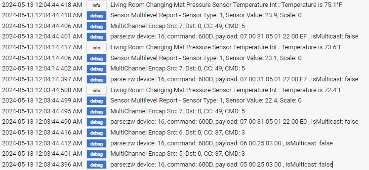
And here are some logs from my trial runs today:
Thanks for your help!
This is not right. The child device type should be something like "Fibaro FGBS-222 Child Analog Input" and you shouldn't be able to change it (greyed-out). That means it is not installed correctly. Did you enter "yes" and press "reinstall" in the parent device? See the top of this thread for installation, I updated it today to reflect changes...
Looking at your spreadsheet, at least the sensor seems to be working...
I see some "warn" in the log, one parameter is out of range and a few are not set correctly. Did you do a "configure" after changing them.
Using the preferences, you can configure the implant to send automatically a report every minute (or more) or every time the voltage changes by more than a certain amount, but it is not fast, try it and see.
For faster polling, you would add the "Rule Machine" built-in app and create a rule inside it triggered every X seconds ("Periodic Schedule")with the action "...Run Custom Action" and select for instance "switch" and then select the analog child device corresponding to you sensor, you can then choose from the menu the "refresh" command.
You can also do basically the same thing from an App that you would write and instantiate but it might be overkill in your case unless you want to do something fancy.
With option 3, you could use a comparator IC to trigger an alarm notification every time the voltage goes below or above a threshold (adjustable using a potentiometer). That would require the threshold to be constant but it has the advantage of eliminating the need to poll the implant every X seconds... Another more flexible and less hardware intensive option would be to use something like a Z-UNO instead of the implant.
This is what the child device page should look like:
Download the Hubitat app