All of the GPIO pins on the Wemos D1 mini are 3.3 volts. But you are correct, D1 will control the relay and D2 will read the contact sensor.
I was able to get the relay above and got a 3 back of boards https://www.amazon.com/gp/product/B076F53B6S/
I seem to be able to get the sketch on the board and running, However, I don't think I am defining the correct pin for the relay. Any ideas? Currently I am using the example code for LinkNode R4...
//******************************************************************************************
//Define which Arduino Pins will be used for each device
//******************************************************************************************
#define PIN_S2 16 //LinkNode R4 Board Marking D3
#define PIN_S3 14 //LinkNode R4 Board Marking D4
#define PIN_S4 12 //LinkNode R4 Board Marking D10
#define PIN_S5 13 //LinkNode R4 Board Marking D8
I know these are not right but don't know what else to set them as.
Thanks..
What pin on the Wemos D1 mini are you connecting the relay to? That will be what you define the pin as. Also, you have to show how you are defining your costructor for the door control. What are you calling the pin for the relay? Something like PIN_RELAY? Showing your whole sketch (with preformatting as code) would be a big help.
I'd take a look at the below as it talks about the pins that work with St_Anything. My relay though was soldered to D1 and the contact sensor was D2.
Also don't forget to change this code otherwise when the Wemos looses power your door will open.
PIN_DOORCONTROL_RELAY_1, LOW to this PIN_DOORCONTROL_RELAY_1, HIGH
Please do not use the LinkNode example sketch for the Wemos D1 boards. Choose one of the standard ESP8266WiFi sketches.
1 Like
Thanks for that piece of advice. I am restarting with ST_Anything_Relays_ESP8266.ino
As far as I can tell the relay is on D1. Just in case, I have commented out as much as I can find for the 2nd and 3rd relays.
Side Note:: I am a DNS/DHCP admin, so I was pleasantly surprised to see these little things can use DHCP leases. Eventually, I would like to setup all of my smart devices to use DHCP and have that register them in my local DNS (My Ras Pi boards already do that). Currently, I manually add each device to my DNS DB (well not manually, I have a script for it).
Side Note 2:: I'n not sure if you can "include" things in a Arduino, but wouldn't it be easier to refer to a file so all of your sketches can just use Same SSID and Password info?
My current status is.. The devices will get on the wifi network. But Hubitat can not connect to them even though it seems like something is trying to connect.
sys:12019-08-11 06:09:51.515 pm warnReceived data from 192.168.1.221, no matching device found for 192.168.1.221, C0A801DD:FFC5, 84F3EBEE278A or C0A801DD.
sys:12019-08-11 06:09:51.000 pm warnReceived data from 192.168.1.221, no matching device found for 192.168.1.221, C0A801DD:D3AF, 84F3EBEE278A or C0A801DD.
sys:12019-08-11 06:09:50.461 pm warnReceived data from 192.168.1.221, no matching device found for 192.168.1.221, C0A801DD:F02B, 84F3EBEE278A or C0A801DD.
dev:3262019-08-11 06:09:50.073 pm infoZooz-Plug power is 6.9W
//******************************************************************************************
//  File: ST_Anything_LinkNodeR4_ESP8266WiFi.ino
//  Authors: Dan G Ogorchock & Daniel J Ogorchock (Father and Son)
//
//  Summary:  This Arduino Sketch, along with the ST_Anything library and the revised SmartThings
//            library, demonstrates the ability of one LinkNodeR4 ESP8266 to
//            implement a multi input/output custom device for integration into SmartThings.
//            The ST_Anything library takes care of all of the work to schedule device updates
//            as well as all communications with the LinkNodeR4 ESP8266's WiFi.
//
//            ST_Anything_LinkNodeR4 implements the following Capabilities as a demo of what
//            is possible with a single LinkSprite LinkNode R4 board
//              - 4 x Switch devices (used to turn on a digital output (e.g. LED, relay, etc...)
//
//  Board Programming details available at: http://linksprite.com/wiki/index.php?title=File:211201004-GPIO.png
//
//  Change History:
//
//    Date        Who            What
//    ----        ---            ----
//    2019-03-26  Dan Ogorchock  Original Creation
//
//******************************************************************************************
//******************************************************************************************
// SmartThings Library for ESP8266WiFi
//******************************************************************************************
#include <SmartThingsESP8266WiFi.h>

//******************************************************************************************
// ST_Anything Library
//******************************************************************************************
#include <Constants.h>       //Constants.h is designed to be modified by the end user to adjust behavior of the ST_Anything library
#include <Device.h>          //Generic Device Class, inherited by Sensor and Executor classes
#include <Sensor.h>          //Generic Sensor Class, typically provides data to ST Cloud (e.g. Temperature, Motion, etc...)
#include <Executor.h>        //Generic Executor Class, typically receives data from ST Cloud (e.g. Switch)
#include <InterruptSensor.h> //Generic Interrupt "Sensor" Class, waits for change of state on digital input
#include <PollingSensor.h>   //Generic Polling "Sensor" Class, polls Arduino pins periodically
#include <Everything.h>      //Master Brain of ST_Anything library that ties everything together and performs ST Shield communications

#include <EX_Switch.h>       //Implements an Executor (EX) via a digital output to a relay
#include <S_TimedRelay.h>    //Implements a Sensor to control a digital output pin with timing capabilities


//******************************************************************************************
//Define which Arduino Pins will be used for each device
//******************************************************************************************
#define PIN_S2              16  //LinkNode R4 Board Marking D3
#define PIN_S3              14  //LinkNode R4 Board Marking D4
#define PIN_S4              12  //LinkNode R4 Board Marking D10
#define PIN_S5              13  //LinkNode R4 Board Marking D8

//******************************************************************************************
//ESP8266 WiFi Information
//******************************************************************************************
String str_ssid     = "Public";                           //  <---You must edit this line!
String str_password = "empty_password";                   //  <---You must edit this line!
IPAddress ip(192, 168, 1, 222);       //Device IP Address       //  <---You must edit this line!
IPAddress gateway(192, 168, 1, 1);    //Router gateway          //  <---You must edit this line!
IPAddress subnet(255, 255, 255, 0);   //LAN subnet mask         //  <---You must edit this line!
IPAddress dnsserver(192, 168, 1, 1);  //DNS server              //  <---You must edit this line!
const unsigned int serverPort = 8090; // port to run the http server on

// Smartthings Hub Information
//IPAddress hubIp(192, 168, 1, 149);  // smartthings hub ip       //  <---You must edit this line!
//const unsigned int hubPort = 39500; // smartthings hub port

// Hubitat Hub Information
IPAddress hubIp(192, 168, 1, 188);    // hubitat hub ip         //  <---You must edit this line!
const unsigned int hubPort = 39501;   // hubitat hub port

//******************************************************************************************
//st::Everything::callOnMsgSend() optional callback routine.  This is a sniffer to monitor
//    data being sent to ST.  This allows a user to act on data changes locally within the
//    Arduino sktech.
//******************************************************************************************
void callback(const String &msg)
{
  //  Serial.print(F("ST_Anything Callback: Sniffed data = "));
  //  Serial.println(msg);

  //TODO:  Add local logic here to take action when a device's value/state is changed

  //Masquerade as the ThingShield to send data to the Arduino, as if from the ST Cloud (uncomment and edit following line)
  //st::receiveSmartString("Put your command here!");  //use same strings that the Device Handler would send
}

//******************************************************************************************
//Arduino Setup() routine
//******************************************************************************************
void setup()
{
  //******************************************************************************************
  //Declare each Device that is attached to the Arduino
  //  Notes: - For each device, there is typically a corresponding "tile" defined in your
  //           SmartThings Device Hanlder Groovy code, except when using new COMPOSITE Device Handler
  //         - For details on each device's constructor arguments below, please refer to the
  //           corresponding header (.h) and program (.cpp) files.
  //         - The name assigned to each device (1st argument below) must match the Groovy
  //           Device Handler names.  (Note: "temphumid" below is the exception to this rule
  //           as the DHT sensors produce both "temperature" and "humidity".  Data from that
  //           particular sensor is sent to the ST Hub in two separate updates, one for
  //           "temperature" and one for "humidity")
  //         - The new Composite Device Handler is comprised of a Parent DH and various Child
  //           DH's.  The names used below MUST not be changed for the Automatic Creation of
  //           child devices to work properly.  Simply increment the number by +1 for each duplicate
  //           device (e.g. contact1, contact2, contact3, etc...)  You can rename the Child Devices
  //           to match your specific use case in the ST Phone Application.
  //******************************************************************************************
  //Polling Sensors

  //Interrupt Sensors

  //Special sensors/executors (uses portions of both polling and executor classes)

  //Executors
  static st::EX_Switch executor1(F("switch1"), PIN_S2, LOW, false);  //Non-Inverted logic for "Active High" Relay Board
  static st::EX_Switch executor2(F("switch2"), PIN_S3, LOW, false);  //Non-Inverted logic for "Active High" Relay Board
  static st::EX_Switch executor3(F("switch3"), PIN_S4, LOW, false);  //Non-Inverted logic for "Active High" Relay Board
  static st::EX_Switch executor4(F("switch4"), PIN_S5, LOW, false);  //Non-Inverted logic for "Active High" Relay Board

  //*****************************************************************************
  //  Configure debug print output from each main class
  //  -Note: Set these to "false" if using Hardware Serial on pins 0 & 1
  //         to prevent communication conflicts with the ST Shield communications
  //*****************************************************************************
  st::Everything::debug = true;
  st::Executor::debug = true;
  st::Device::debug = true;
  st::PollingSensor::debug = true;
  st::InterruptSensor::debug = true;

  //*****************************************************************************
  //Initialize the "Everything" Class
  //*****************************************************************************

  //Initialize the optional local callback routine (safe to comment out if not desired)
  st::Everything::callOnMsgSend = callback;

  //Create the SmartThings ESP8266WiFi Communications Object
  //STATIC IP Assignment - Recommended
  st::Everything::SmartThing = new st::SmartThingsESP8266WiFi(str_ssid, str_password, ip, gateway, subnet, dnsserver, serverPort, hubIp, hubPort, st::receiveSmartString, "OfficeESP");

  //DHCP IP Assigment - Must set your router's DHCP server to provice a static IP address for this device's MAC address
  //st::Everything::SmartThing = new st::SmartThingsESP8266WiFi(str_ssid, str_password, serverPort, hubIp, hubPort, st::receiveSmartString);

  //Run the Everything class' init() routine which establishes WiFi communications with SmartThings Hub
  st::Everything::init();

  //*****************************************************************************
  //Add each sensor to the "Everything" Class
  //*****************************************************************************

  //*****************************************************************************
  //Add each executor to the "Everything" Class
  //*****************************************************************************
  st::Everything::addExecutor(&executor1);
  st::Everything::addExecutor(&executor2);
  st::Everything::addExecutor(&executor3);
  st::Everything::addExecutor(&executor4);

  //*****************************************************************************
  //Initialize each of the devices which were added to the Everything Class
  //*****************************************************************************
  st::Everything::initDevices();
}

//******************************************************************************************
//Arduino Loop() routine
//******************************************************************************************
void loop()
{
  //*****************************************************************************
  //Execute the Everything run method which takes care of "Everything"
  //*****************************************************************************
  st::Everything::run();
}Yeah, as Dan said, use the ST_Anything_GarageDoors_ESP8266WiFi example Sketch. That is going to be exactly what you're looking for.
1 Like
This error indicates that you have not completed the manual addition and configuration of the HubDuino Parent Ethernet device. Once you fill in the Parent Device’s field for the ESP8266’s IP Address, Port, and MAC address, the error above will go away.
Here is my weekly update. I have This board https://www.amazon.com/gp/product/B076F53B6S/ connected to this relay https://www.amazon.com/gp/product/B078CQZK1
In Hubitat everything looks like it's working. However, the key might be that I don't have a wired sensor. I already have a Iris Contact sensor attached to the door on a mount that I made. If this means I need to just add this as a Button, please show me how.
**I guess I should mention that it seems to work except the relay never moves. I can manually trip the relay by shorting the pins D1 and D2 together (learned this on accident). **
I installed this sketch as edited below (without Information, I removed references to the 2nd door. As I only have one relay.
As always thanks to Dan for the code and to everyone else for the help
//******************************************************************************************
//  File: ST_Anything_GarageDoors_ESP8266WiFi.ino
//  Authors: Dan G Ogorchock & Daniel J Ogorchock (Father and Son)
//
//  Summary:  This Arduino Sketch, along with the ST_Anything library and the revised SmartThings
//            library, demonstrates the ability of one NodeMCU ESP8266 to
//            implement a multi input/output custom device for integration into SmartThings.
//            The ST_Anything library takes care of all of the work to schedule device updates
//            as well as all communications with the NodeMCU ESP8266's WiFi.
//
//            ST_Anything_Multiples implements the following ST Capabilities as a demo of what is possible with a single NodeMCU ESP8266
//              - 2 x Door Control devices (used typically for Garage Doors - input pin (contact sensor) and output pin (relay switch)
//
//  Change History:
//
//    Date        Who            What
//    ----        ---            ----
//    2019-01-24  Dan Ogorchock  Original Creation
//
//******************************************************************************************
//******************************************************************************************
// SmartThings Library for ESP8266WiFi
//******************************************************************************************
#include <SmartThingsESP8266WiFi.h>

//******************************************************************************************
// ST_Anything Library
//******************************************************************************************
#include <Constants.h>       //Constants.h is designed to be modified by the end user to adjust behavior of the ST_Anything library
#include <Device.h>          //Generic Device Class, inherited by Sensor and Executor classes
#include <Sensor.h>          //Generic Sensor Class, typically provides data to ST Cloud (e.g. Temperature, Motion, etc...)
#include <Executor.h>        //Generic Executor Class, typically receives data from ST Cloud (e.g. Switch)
#include <InterruptSensor.h> //Generic Interrupt "Sensor" Class, waits for change of state on digital input
#include <PollingSensor.h>   //Generic Polling "Sensor" Class, polls Arduino pins periodically
#include <Everything.h>      //Master Brain of ST_Anything library that ties everything together and performs ST Shield communications

#include <PS_Illuminance.h>  //Implements a Polling Sensor (PS) to measure light levels via a photo resistor

#include <PS_TemperatureHumidity.h>  //Implements a Polling Sensor (PS) to measure Temperature and Humidity via DHT library
#include <PS_DS18B20_Temperature.h>  //Implements a Polling Sesnor (PS) to measure Temperature via DS18B20 libraries
#include <PS_Water.h>        //Implements a Polling Sensor (PS) to measure presence of water (i.e. leak detector)
#include <IS_Motion.h>       //Implements an Interrupt Sensor (IS) to detect motion via a PIR sensor
#include <IS_Contact.h>      //Implements an Interrupt Sensor (IS) to monitor the status of a digital input pin
#include <IS_Smoke.h>        //Implements an Interrupt Sensor (IS) to monitor the status of a digital input pin
#include <IS_DoorControl.h>  //Implements an Interrupt Sensor (IS) and Executor to monitor the status of a digital input pin and control a digital output pin
#include <IS_Button.h>       //Implements an Interrupt Sensor (IS) to monitor the status of a digital input pin for button presses
#include <EX_Switch.h>       //Implements an Executor (EX) via a digital output to a relay
#include <EX_Alarm.h>        //Implements Executor (EX)as an Alarm Siren capability via a digital output to a relay
#include <S_TimedRelay.h>    //Implements a Sensor to control a digital output pin with timing capabilities

//*************************************************************************************************
//NodeMCU v1.0 ESP8266-12e Pin Definitions (makes it much easier as these match the board markings)
//*************************************************************************************************
//#define LED_BUILTIN 16
//#define BUILTIN_LED 16
//
//#define D0 16  //no internal pullup resistor
//#define D1  5
//#define D2  4
//#define D3  0  //must not be pulled low during power on/reset, toggles value during boot
//#define D4  2  //must not be pulled low during power on/reset, toggles value during boot
//#define D5 14
//#define D6 12
//#define D7 13
//#define D8 15  //must not be pulled high during power on/reset

//******************************************************************************************
//Define which Arduino Pins will be used for each device
//******************************************************************************************

//Garage Door Pins
#define PIN_DOORCONTROL_CONTACT_1 D1  //SmartThings Capabilty "Door Control"
#define PIN_DOORCONTROL_RELAY_1   D2  //SmartThings Capabilty "Door Control"
//#define PIN_DOORCONTROL_CONTACT_2 D5  //SmartThings Capabilty "Door Control"
//#define PIN_DOORCONTROL_RELAY_2   D6  //SmartThings Capabilty "Door Control"

//******************************************************************************************
//ESP8266 WiFi Information
//******************************************************************************************
String str_ssid     = "NO-VALID-SSID";                           //  <---You must edit this line!
String str_password = "Blank_Password";                   //  <---You must edit this line!
IPAddress ip(192, 168, 1, 221);       //Device IP Address       //  <---You must edit this line!
IPAddress gateway(192, 168, 1, 1);    //Router gateway          //  <---You must edit this line!
IPAddress subnet(255, 255, 255, 0);   //LAN subnet mask         //  <---You must edit this line!
IPAddress dnsserver(192, 168, 1, 1);  //DNS server              //  <---You must edit this line!
const unsigned int serverPort = 8090; // port to run the http server on

// Smartthings / Hubitat Hub TCP/IP Address
IPAddress hubIp(192, 168, 1, 188);    // smartthings/hubitat hub ip //  <---You must edit this line!

// SmartThings / Hubitat Hub TCP/IP Address: UNCOMMENT line that corresponds to your hub, COMMENT the other
//const unsigned int hubPort = 39500;   // smartthings hub port
const unsigned int hubPort = 39501;   // hubitat hub port

//******************************************************************************************
//st::Everything::callOnMsgSend() optional callback routine.  This is a sniffer to monitor
//    data being sent to ST.  This allows a user to act on data changes locally within the
//    Arduino sktech.
//******************************************************************************************
void callback(const String &msg)
{
//  Serial.print(F("ST_Anything Callback: Sniffed data = "));
//  Serial.println(msg);

  //TODO:  Add local logic here to take action when a device's value/state is changed

  //Masquerade as the ThingShield to send data to the Arduino, as if from the ST Cloud (uncomment and edit following line)
  //st::receiveSmartString("Put your command here!");  //use same strings that the Device Handler would send
}

//******************************************************************************************
//Arduino Setup() routine
//******************************************************************************************
void setup()
{
  //******************************************************************************************
  //Declare each Device that is attached to the Arduino
  //  Notes: - For each device, there is typically a corresponding "tile" defined in your
  //           SmartThings Device Hanlder Groovy code, except when using new COMPOSITE Device Handler
  //         - For details on each device's constructor arguments below, please refer to the
  //           corresponding header (.h) and program (.cpp) files.
  //         - The name assigned to each device (1st argument below) must match the Groovy
  //           Device Handler names.  (Note: "temphumid" below is the exception to this rule
  //           as the DHT sensors produce both "temperature" and "humidity".  Data from that
  //           particular sensor is sent to the ST Hub in two separate updates, one for
  //           "temperature" and one for "humidity")
  //         - The new Composite Device Handler is comprised of a Parent DH and various Child
  //           DH's.  The names used below MUST not be changed for the Automatic Creation of
  //           child devices to work properly.  Simply increment the number by +1 for each duplicate
  //           device (e.g. contact1, contact2, contact3, etc...)  You can rename the Child Devices
  //           to match your specific use case in the ST Phone Application.
  //******************************************************************************************
  //Polling Sensors

  //Interrupt Sensors
  static st::IS_DoorControl sensor1(F("doorControl1"), PIN_DOORCONTROL_CONTACT_1, LOW, true, PIN_DOORCONTROL_RELAY_1, HIGH, true, 1000, 1000);
  //static st::IS_DoorControl sensor2(F("doorControl2"), PIN_DOORCONTROL_CONTACT_2, LOW, true, PIN_DOORCONTROL_RELAY_2, LOW, true, 1000, 1000);

  //Executors

  //*****************************************************************************
  //  Configure debug print output from each main class
  //  -Note: Set these to "false" if using Hardware Serial on pins 0 & 1
  //         to prevent communication conflicts with the ST Shield communications
  //*****************************************************************************
  st::Everything::debug=true;
  st::Executor::debug=true;
  st::Device::debug=true;
  st::PollingSensor::debug=true;
  st::InterruptSensor::debug=true;

  //*****************************************************************************
  //Initialize the "Everything" Class
  //*****************************************************************************

  //Initialize the optional local callback routine (safe to comment out if not desired)
  st::Everything::callOnMsgSend = callback;

  //Create the SmartThings ESP8266WiFi Communications Object
    //STATIC IP Assignment - Recommended
    st::Everything::SmartThing = new st::SmartThingsESP8266WiFi(str_ssid, str_password, ip, gateway, subnet, dnsserver, serverPort, hubIp, hubPort, st::receiveSmartString, "OfficeESP");

    //DHCP IP Assigment - Must set your router's DHCP server to provice a static IP address for this device's MAC address
    //st::Everything::SmartThing = new st::SmartThingsESP8266WiFi(str_ssid, str_password, serverPort, hubIp, hubPort, st::receiveSmartString);

  //Run the Everything class' init() routine which establishes WiFi communications with SmartThings Hub
  st::Everything::init();

  //*****************************************************************************
  //Add each sensor to the "Everything" Class
  //*****************************************************************************
  st::Everything::addSensor(&sensor1);
  //st::Everything::addSensor(&sensor2);

  //*****************************************************************************
  //Add each executor to the "Everything" Class
  //*****************************************************************************

  //*****************************************************************************
  //Initialize each of the devices which were added to the Everything Class
  //*****************************************************************************
  st::Everything::initDevices();

}

//******************************************************************************************
//Arduino Loop() routine
//******************************************************************************************
void loop()
{
  //*****************************************************************************
  //Execute the Everything run method which takes care of "Everything"
  //*****************************************************************************
  st::Everything::run();
}
I have installed the parent virtual device and the child looks good in the GUI and on the Serial Console (Output below)
20:45:15.830 -> Enter the following three lines of data into ST App on your phone!
20:45:15.830 -> localIP = 192.168.1.221
20:45:15.830 -> serverPort = 8090
20:45:15.830 -> MAC Address = 84F3EBEE278A
20:45:15.865 ->
20:45:15.865 -> SSID = NO-VALID-SSID
20:45:15.865 -> PASSWORD = Blank_Password
20:45:15.865 -> hubIP = 192.168.1.188
20:45:15.865 -> hubPort = 39501
20:45:15.865 -> RSSI = -59
20:45:15.865 -> hostName = OfficeESP
20:45:15.865 ->
20:45:15.865 -> SmartThingsESP8266WiFI: Intialized
20:45:15.865 ->
20:45:15.865 -> Disabling ESP8266 WiFi Access Point
20:45:15.865 ->
20:45:15.865 -> ArduinoOTA Ready
20:45:15.865 -> IP address: 192.168.1.221
20:45:15.865 -> ArduionOTA Host Name: OfficeESP
20:45:15.865 ->
20:45:15.865 -> Everything: init ended
20:45:15.865 -> Everything: Free RAM = 49208
20:45:15.865 -> Everything: adding sensor named doorControl1
20:45:15.865 -> Everything: Free RAM = 49208
20:45:15.900 -> Everything: initDevices started
20:45:15.900 -> Everything: Free RAM = 49208
20:45:15.900 -> Everything: initDevices ended
20:45:15.900 -> Everything: Free RAM = 49208
20:45:15.969 -> Everything: Sending: doorControl1 closed
20:46:04.442 -> Everything: Received: HTTP/1.1
20:46:04.442 -> Host: 192.168.1.221:8090
20:46:04.442 -> Connection: keep-alive
20:46:04.442 -> Upgrade-Insecure-Requests: 1
20:46:15.799 -> Everything: Received: favicon.ico HTTP/1.1
20:46:15.799 -> Host: 192.168.1.221:8090
20:46:15.799 -> Connection: keep-alive
20:46:16.814 -> Everything: Received: HTTP/1.1
20:46:16.849 -> Host: 192.168.1.221:8090
20:46:16.849 -> Connection: keep-alive
20:46:16.849 -> Cache-Control: max-age=0
20:46:16.849 -> Upgrade-Insecure-Requests: 1
20:46:17.021 -> Host: 192.168.1.221:8090
20:46:17.021 -> Connection: keep-alive
20:47:11.428 -> Everything: Free Ram = 47832
20:47:11.428 -> Everything: Free Ram = 47832
20:48:11.412 -> Everything: Free Ram = 48024
20:48:11.412 -> Everything: Free Ram = 48024
20:48:37.969 -> Everything: Received: refresh
20:48:37.969 -> Everything: Sending: doorControl1 closed
20:48:59.950 -> Everything: Received: doorControl1 on
20:48:59.950 -> IS_ContactRelay::beSmart s = on
20:48:59.950 -> Everything: Sending: doorControl1 opening ....
The ST_Anything door control device requires a hardwired magnetic reed switch.
Your link for the relay does not work, so I can’t help troubleshoot the relay output.
Sorry about that.
Flip flop D1 and D2 in the sketch in the following two lines of code. The Wemos D1 Relay shield uses pin D1, not D2.
Should look like
#define PIN_DOORCONTROL_CONTACT_1 D2 //SmartThings Capabilty "Door Control"
#define PIN_DOORCONTROL_RELAY_1 D1 //SmartThings Capabilty "Door Control"
I uploaded the sketch with the changes you suggest. I see the calls come in on the Serial console. Do I need to remove the parent and re-discover the device?
EDIT:: Also, what pins do I connect the hardwired magnetic reed switch to? I assume D1 and ...??
Would I be better off wiring a sensor to the door or just making this a "button" to push to open/close the door?`
No....the reed switch should be connected to D2
![]()
The relay is controlled by D2. The other side of the reed should be connected to ground.
The Magnetic Contact sensor should be connected to pins D2 and GND.
The Relay Shield should 'just work' once installed on the Wemos board. It uses pin D1 to activate it.
No, no need to change the parent device. Just change the sketch as I showed earlier and re-upload it to the Wemos board.
I must suck at soldering more than I thought or something. The Relay will work if I manually trip it. (Can anyone tell me what the Correct way to test if the relay is taking commands on the correct pin or if the board is sending the correct signal?)
I have another D1 that I am going to solder the headers onto it and try again.
If I get this working... Any idea how I would add 2 LED lights and a DHT-22 to the stack and get sensor data?
Let's get what you have working first.
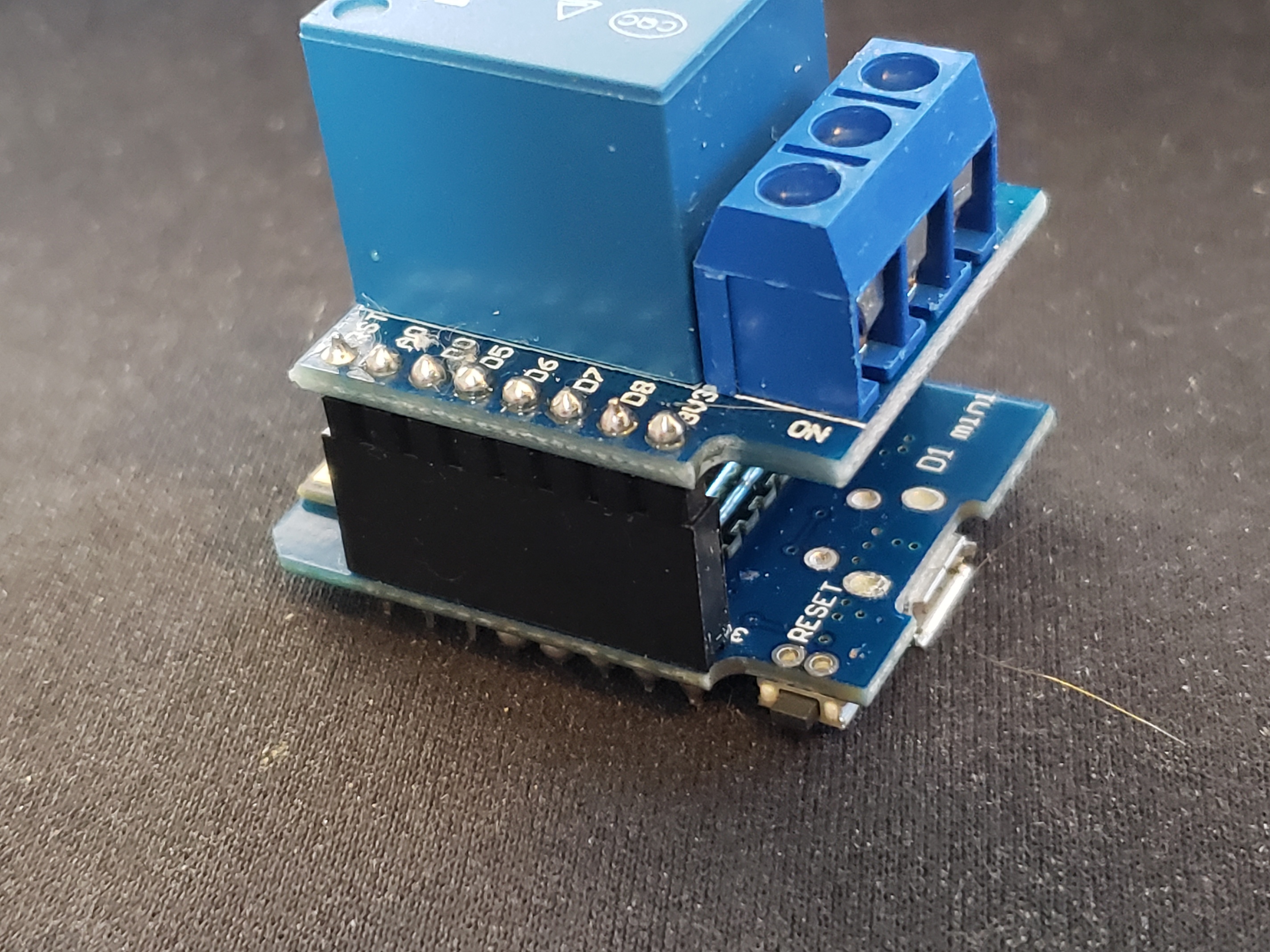
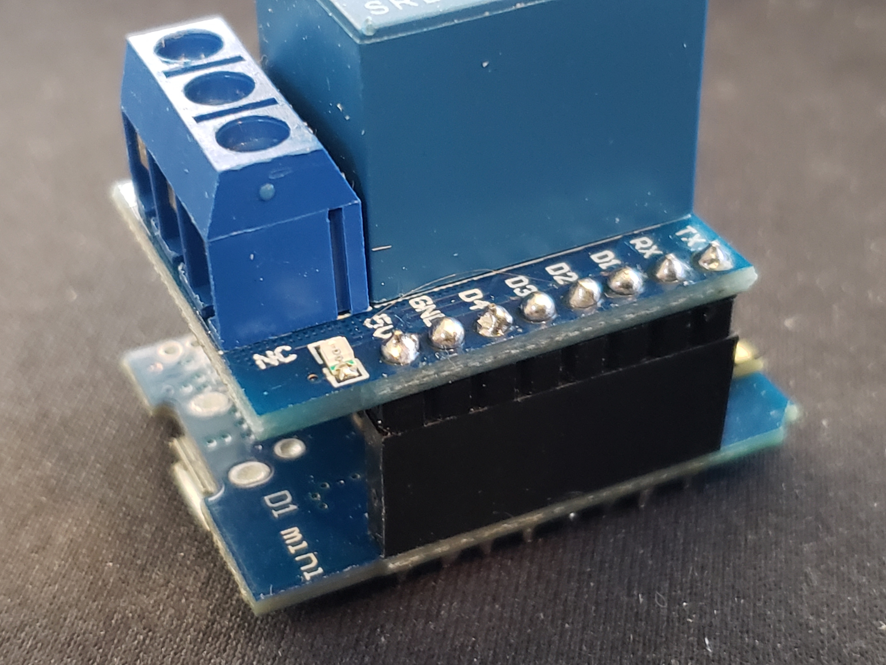
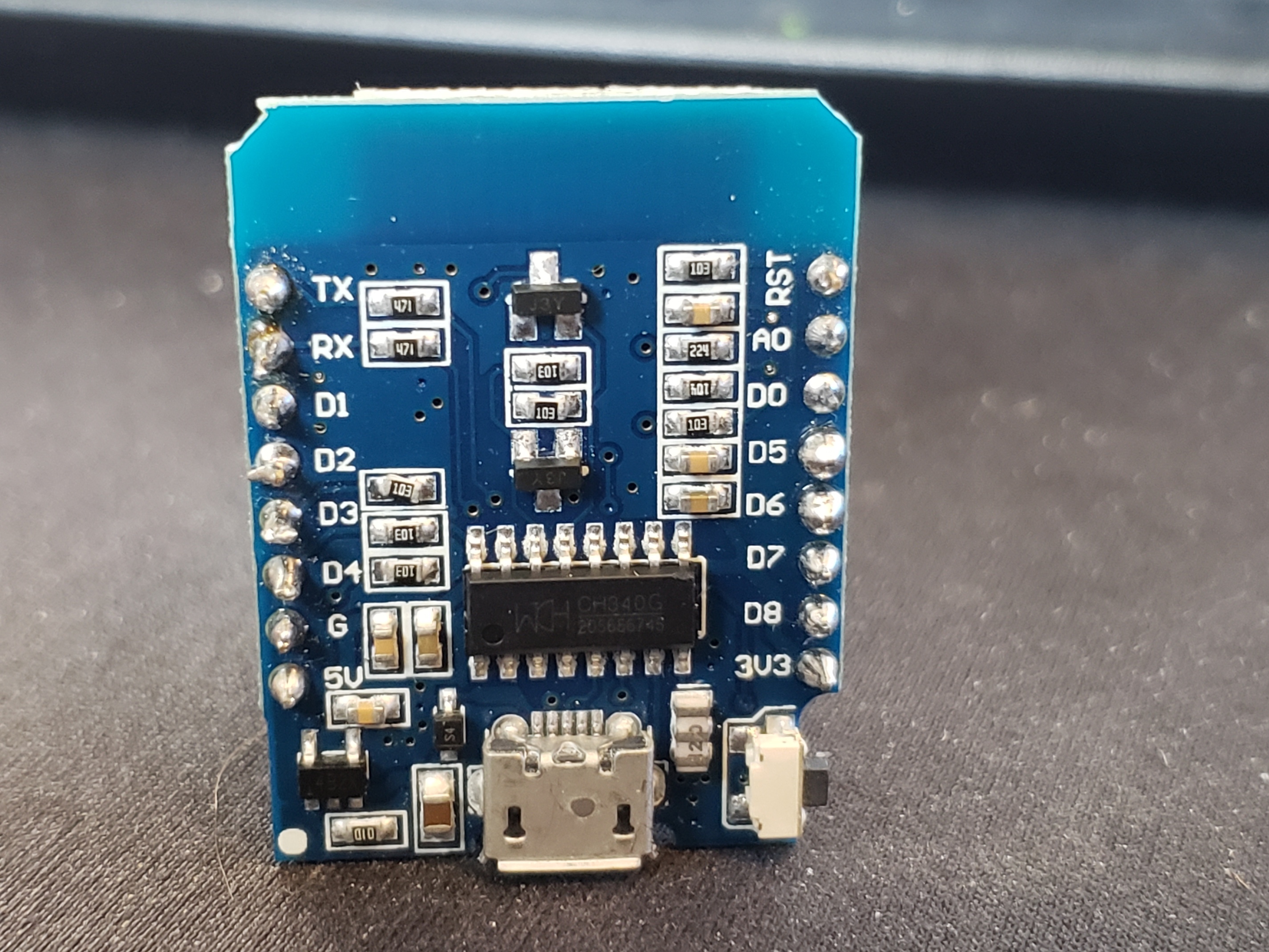
If you have your board pluged into your pc, in the Arduino IDE you can open serial monitor. That will show you want command are being received by the board and what the board is doing. When you say you can "manually trip the relay, what exactly are you doing? Do you have the relay board in the correct alignment with the D1? The pins have to match up or it won't work. If you could take a picture of how you have it wired, that might be helpful.
1 Like
Okay, and when you plug this into your PC, open up the Serial Monitor within the Arduino IDE. From there you can see what messages it is receiving. Also, did you turn Debug logging on in HE? Did you look that the logs in HE? Do you have all the necessary drivers loaded for the child devices?
I see messages in the Serial Monitor for the reed switch and the relay commands as well
13:58:59.236 -> ⸮Everything: Sending: doorControl1 open
13:58:59.513 -> Everything: Sending: doorControl1 closed
13:58:59.821 -> Everything: Sending: doorControl1 open
13:59:00.817 -> Everything: Sending: doorControl1 closed

