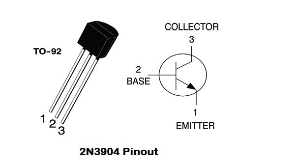
I am using a Linear Wadawz-1 z-wave door/window Transmitter. I have a voltmeter.I have breadboarded circuit using a 2n3904 transistor and a 3 volt battery. I use a 33k ohm resistor in the collector and a 500 ohm resistor in the base circuit. I get 2.99 volts with no input voltage to the base and 0.1 with a 5 volt usb iPad charger as the input supply voltage. When I connect to the wadawz-1 as described in my post to ritchierich with only the resistor in the base circuit, the transistor heats up and is destroyed. I am building this for a family member and I don't have a z-wave hub to verify output signal, because I can't pair it .
I hope this will help you. The transistor should not get hot. I think you have the positive and negative wires of the USB cable swapped. Don't go by the wire colors on the USB cable red is not always positive and black is not always negative. Also need to use the voltmeter to determine the positive and negative terminals on the sensor.
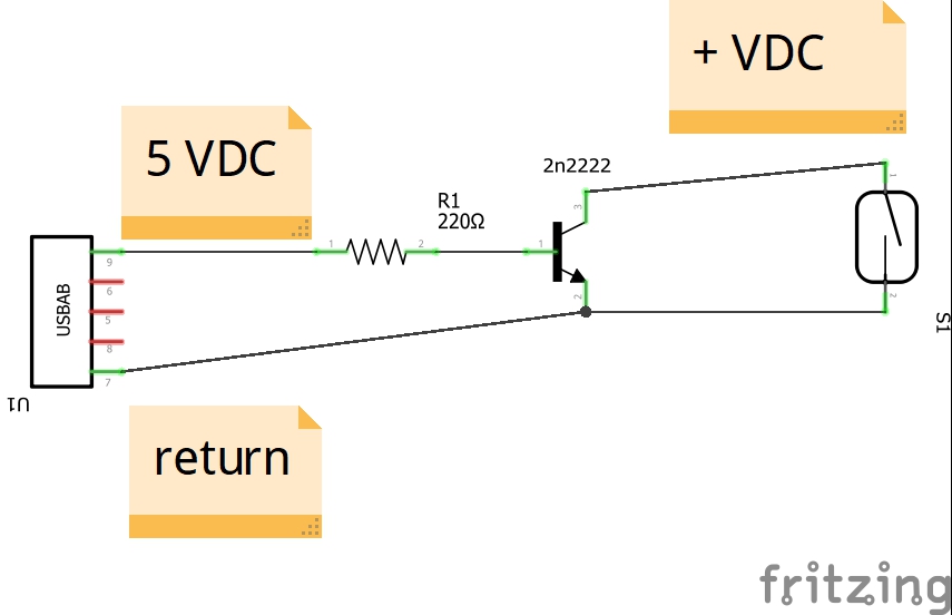
- First check the USB cable voltage the positive wire should go to one lead of the resistor, the other lead of the resistor should go to the base of the transistor.
- The negative wire on the USB cable should go to the emitter of the transistor.
- The positive terminal of the sensor should go to the collector of the transistor.
- The negative terminal of the sensor should go to the emitter of the transistor.
1 Like
OK. I checked the voltages, and I had them all correct. I had it wired as you identified. I set it up again, and the transistor does now not get hot. I get a small voltage .1 volts across the sensor when the 5V supply is not connected and 0V when it is. But it has not been "included" to a network, because I don't have one. I do have a blinking red light on the sensor which is what the instructions says indicates it is not yet "Included". I had the tamper switch taped down. I guess I need to attempt get it on a network and hope it works.
Thanks for your help. I will let you know the results, but it may be a week or so. Have to mail it to the owner.
1 Like
It sounds like it should be working.
I would like to build one of these. I have a spare Dome contact sensor to use. I pretty much get what is going on however would it be possible to publish a circuit diagram? That would fill in the blanks for me.
Thank you.
I hope this helps.
- First check the USB cable voltage the positive wire should go to one lead of the resistor, the other lead of the resistor should go to the base of the transistor.
- The negative wire on the USB cable should go to the emitter of the transistor.
- The positive terminal of the sensor should go to the collector of the transistor.
- The negative terminal of the sensor should go to the emitter of the transistor.
1 Like
This has probably been said before but when monitoring for mains power outages, if the zwave or zigbee device you are using is routed through a repeater (most are) and it looses power your hub won't get the message because the repeater lost power before it could hand the message off. Eventually your power outage detecting device will re-route but that can take a long time. The only effective way I have found for detecting full mains power outage is using a Raspberry Pi and Node RED to pass a power loss message to the hub via Maker API.
If you only want monitor power on local circuit the ideas presented here is a good solution.
3 Likes
I agree, even if the sensor is near the hub it could be routed through a repeater that lost it’s power.
I used this to build a power loss detector from a water leak detector. It didn't always function right though- like if the power would flicker. Then it might never report power returned. It MOSTLY worked which was nice, but a Ring Range Extender is a much more elegant solution.
https://www.amazon.com/gp/product/B001HLAOR0/ref=ppx_yo_dt_b_search_asin_title?ie=UTF8&psc=1
Thanks
Yes I believe it will.
I actually have a QNAP NAS capable of running Node Red. My problem is I have not found a How to for dummies for setting it up.
The purpose for running on the Raspberry Pi is using the GPIO pin(s) to detect a open/close dry contact relay. My Pi sits at the power panel and triggers when the relay trips. The other nice thing about the Pi is you can do other things such as monitoring LAN connected devices, Internet connection, website connection. But I find it indispensable for power monitoring. Be it a 200ms flicker to an extended outage.
Ok, I'll bite. Are you willing to share the details? It would be a nice introduction the the Pi world for me.
There are several threads on this board that go into a huge amount of detail with step-by-step instructions. Just search keyword Node-RED and absorb the many things you can do.
To go into step-by-step detail here would not be appropriate but these threads should get you there;
1 Like
Will do
@ritchierich may be able to point you in the right direction.
2 Likes
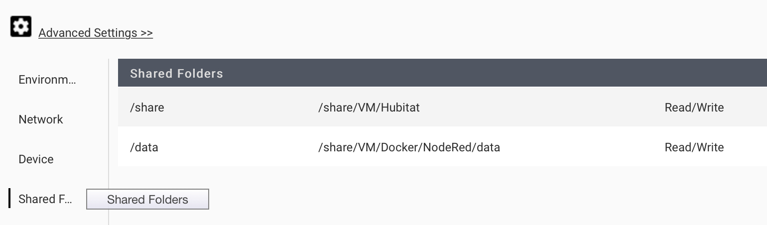
If you have Container Station it’s very easy and a matter of creating a new container with the nodered/node-red:latest image. From there make sure to setup shared folders. First one below is where I have NodeRed automatically download the HE backups and drop them into a folder on my Qnap. Second data directory is where my flows are saved to a folder on my Qnap for backup purposes - I lost all my flows a few months ago and realized I had not been saving them to a common directory that I was backing up.
Was unable to connect the switch to a z-wave network on a Vera Plus controller. At every attempt to connect it wiped out the entire network. Now the red LED is on continuously and removing the battery and pressing the tamper switch won't even return it to a blinking led. Any ideas?
If anyone is considering building their own monitoring solution, there's a kit on sale now at The Smartest House, using our ZAC98 accessory relay and the Ecolink door sensor:
10 Likes
This has worked great for me. The price is right as well. ($15.00)
https://www.amazon.com/dp/B07FQ6SDKY/ref=cm_sw_em_r_mt_dp_U3-nFbZNNB101
2 Likes
Does it act as a "general" Z-Wave repeater as well? Or is it only Ring capable?