Yeah, it depends on your wiring.
If you have a single latching switch (not 2 way (the correct way of calling a 2nd switch location  )). Then the device goes in the box behind the switch and you install the phase (the correct term for live feed) to power the device, then connect the switch line to the output.
The device will have a input on them aswell depending on the device that will be a common and one input or common and 2 inputs. It also depends on the device what switches you can connect to it ie push to make retractable or latching (one input) or the same and the option to have a centre off retractable switch (2 inputs).
The fibaro dimmer 2 will do all of those modes with the best / easiest to use being centre of retractable using 2 inputs.
Now if you then had a 2 way to another switch location controlling the same load you would have 3 cores of cables from the 1st switch to the 2nd location. depending on how it's wired it will be as simple as this or it could go around the houses but the connection will still be there.
Now again depending on what switches you plan to us will depend on how it's connected to the input of the device. A retractable switch though will just be doubles up in parallel.
So I will be using momentary (retractable) switches in parallel.
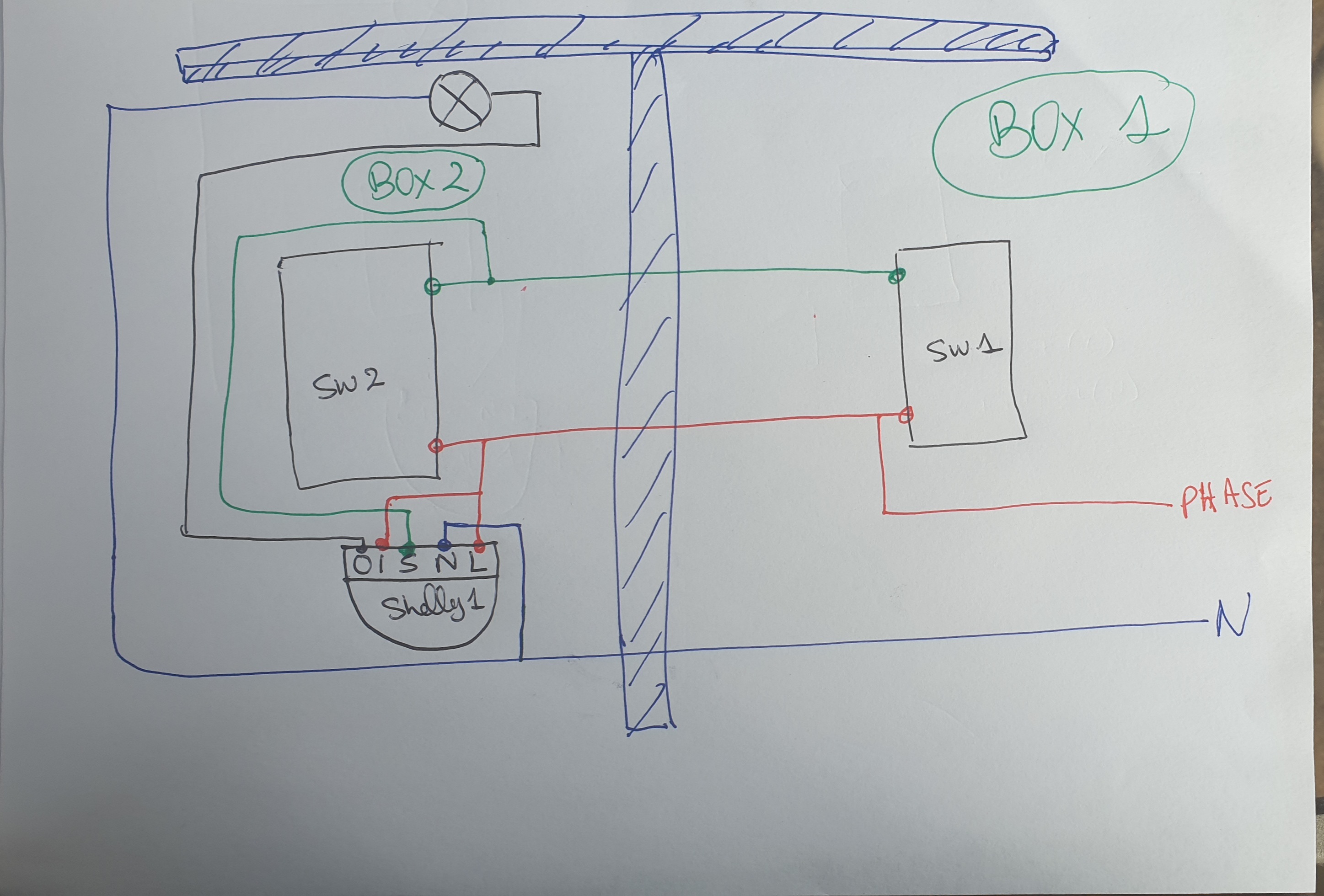
I am not clear on the wiring yet: I have to switch boxes
Box 1: Phase, Neutral, and 2 travelers
Box 2: Neutral coming from box 1, 2 travelers, load + neutral going to light.
And that's all I have. So the Shelly 1 is identical to the fibaro FGS (except it is for one applicance, not 2), it has L, N, SW, I, O, and can be configured to be used with latchable or retractable switches.
The way I understand it (I am no electrician, just a courageous DIYer), I am missing a third wire between the 2 boxes ??
Thanks,
Amine.
1 Like
So here is my understanding of the parallel wiring (see drawing below), do you think that would work ? The 2 switches share the phase, and send a pulse to the Switch port of the Shelly 1, who then establishes a connection between Input and output.
1 Like
Thank you so much BorisTheCat, per the wiring diagram above (your parallel idea with momentary switch, it works perfectly ! I hope this can help others or give them ideas, this solve the problem of not having the L in the same switch box as the load going to the light bulb.
Although I may have given you the idea, you did it on your own. I didn't know exactly what device you had and in this case the "common" was also the phase so it meant you needed less cores. The device is also has "Volt free relay" so well done on connecting it all up.