According to the provided picture it looks like a case ...
I've had several A/C guys replumb the drain line and it still clogs and the secondary line with the sensor gets triggered. For some reason, after I clear the drain line, the secondary line holds water and doesn't drain back into the A/C unit. So the A/C system remains off. I have to then climb in the attic drain the secondary line and all is good. What I'm doing with this motorized value is the same thing and I don't have to get up in the attic.
Forgot to ask. If I change the wiring for the valve relay as you've illustrated, do i change the DC motor mode to "disabled"?
This plumbing problem should/must be fixed without adding extra components.
From the picture it is hard to see why kill switch line is not draining naturally and how this
valve actually helps.
Yeah, you will only be using one relay as a simple on/off switch so the DC Motor mode should be turned off. Not sure what you did exactly to wire it up to both relays but hopefully you did not damage it somehow.
I started from scratch and excluded the device and did a factory reset on the relay just to make sure was good. I rewired the relay and set the device preferences as you suggested. I now have the S1 and S2 child senor devices. The device type is generic component switch. But the current states is blank.
Not sure what's missing
Did you power cycle (unplug and re-plug) the ZEN17 AFTER changing the settings?
It does not send the correct notifications unless you do that, some sort of firmware issue.
Then if you do a refresh, it should populate the states.
That didn't work.
I saw on a YouTube video for a very similar motor (5 wires , same manufacturer and of course the wires are a different color) , It said that the sensor has to be powered separately from the switch for the motor.
Here's the video: https://youtu.be/_n8HoSkzl5w?si=u4vfUKqSWRqsdwbw
I have to figure out how to get power to the sensor wires.
Thats a totally different valve, thats a reverse polarity DC motor, and the sensor wiring shows using a power source with LED lights.
The ZEN17 S#-C inputs do not require power. I have been bench testing mine with just a single piece of wire making contact between the two terminals. Maybe the S and C need to be reversed. I can test it out here in a few minutes with the same wiring and two open/close contacts.
UPDATE: I basically wired it up this same way with 3 pieces of wire, S1-C and S2-C jumped together (acting as the WH common for both switch legs). Then a separate wire connected to the S1 and the S2. If the S1 wire touches the "C" jumper then is trips the S1 input. If the S2 wire touches the C wire then it trips the S2 input.
Basically the C terminal provides a low voltage power, and if you jump that across to any S terminal it will trigger the sensor. According to that diagram they are just basic contact switches which should jump the voltage to the attached terminal when closed. I assume they would close to send the "signal".
Unless there is something else going on that is not shown on that diagram?
It is showing the WH is connected to ground but I take that to just mean a common source for the switch leg.
@jir591
For your application you can forget about sensor wires at least for initial testing.
All what you need - is a simple on/off dry contact relay. ZEN17 has two of them but you need
only one. Once valve becomes functional (i.e could be open/close by switching the relay
on and off) you can add sensors to the equation just to make sure valve is actually reaching
end points.
Let me make sure I understand what you are suggesting:
One stand alone separate wire jumped between s1-c and s2-c
Green sensor wire from valve to s1
yellow sensor wire from valve to s2
white sensor wire to either C ?
Thanks . I have the valve functioning. Open and closing properly. It's the sensor confirmation I am trying to work out.
Yes,
Yes.
And, BTW you don't need a jumper between SC-SC.
These terminals connected together internally.
Yes I believe this is correct, I realized this when I wired it up and was testing it. So WH could go to either of the S-C terminals (the C next to the S1/S2).
The C/VC is a separate trigger for other uses, do not use those at all.
I finally got it working correctly with the help from Zooz support. Here's how they suggested the settings and the wiring.
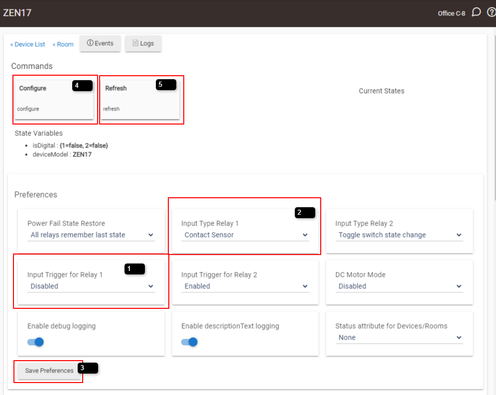
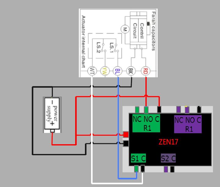
The illustration shows a blue wire but its actually a green wire.
However, their instructions caused the S1 sensor to output the incorrect status "open" when actually closed. I used the Companion settings to reverse the S1 output.
All is good now! Thanks everyone for your help. ![]()
1 Like
Hmmm.. that appears to be essentially exactly what I suggested, but you are only using one of the sensors instead of both. The difference between selecting Contact Sensor and Dry Contact just makes the child be a "contact sensor" vs a "switch" when you use dry contact.
I agree. Just glad you created the advanced driver settings to get the sensor to produce the correct status.
This topic was automatically closed 365 days after the last reply. New replies are no longer allowed.

