Local Control Options for MyQ Garage Door Openers

Did you subscribe to Rboy apps on ST? If yes he has a garage door app that has an acceleration sensor option and has closing and opening states. Might be worth to test it if you have access to it. It runs fine on HE.

2 Likes

FWIW, I received my MHCOZY 1 channel relay today and got everything tested and installed.

Had the same trouble as @DarellCraighead with my ST multisensor and used the same method to correct it. I had just migrated my C5 to my C7 Sunday using Hub Protect and was sure I had reset it along with ~50 other zigbee devices, and checked it then but it was constantly reporting closed. I reset and repaired it again and it didn't change. Doing the configure on it fixed it. I changed it to defaults then back to GDO sensor but I'm not convinced that made a difference.

Anyway, using the Zooz GDO app and set to a Lock Device, I was able to get Alexa working as well after changing the device settings to allow app control and voice control for locks.

Since it's a MyQ setup, I do still have the app if I really want to be certain, but I also have it connected to Amazon Key and have a camera in there, so I'm confidently getting the status.

P.S. I mounted the MHCOZY in an old 8mm data tape cartridge case after clipping off the long leads and putting some Kapton tape on the exposed circuits. Had to cut a hole for the relay to stick out to get the cover closed. Velcro to the GDO braces and parallel wired into the GDO door control.

If anyone has a repo of this app, please post up a link.

Rboy is a SmartThings developer who charges a license fee to gain access to his “device handlers” (what we call drivers in HE) and apps. Unfortunately the license prevents sharing of his code. Here is a link to the details on this app if you want to learn more.

2 Likes

Have a pic of where you soldered the other wires?

I don’t have the after but did take a before because as I get older I am having a hard time seeing up close LOL. With any button you solder on both sides of the button and here is where you solder the wires:

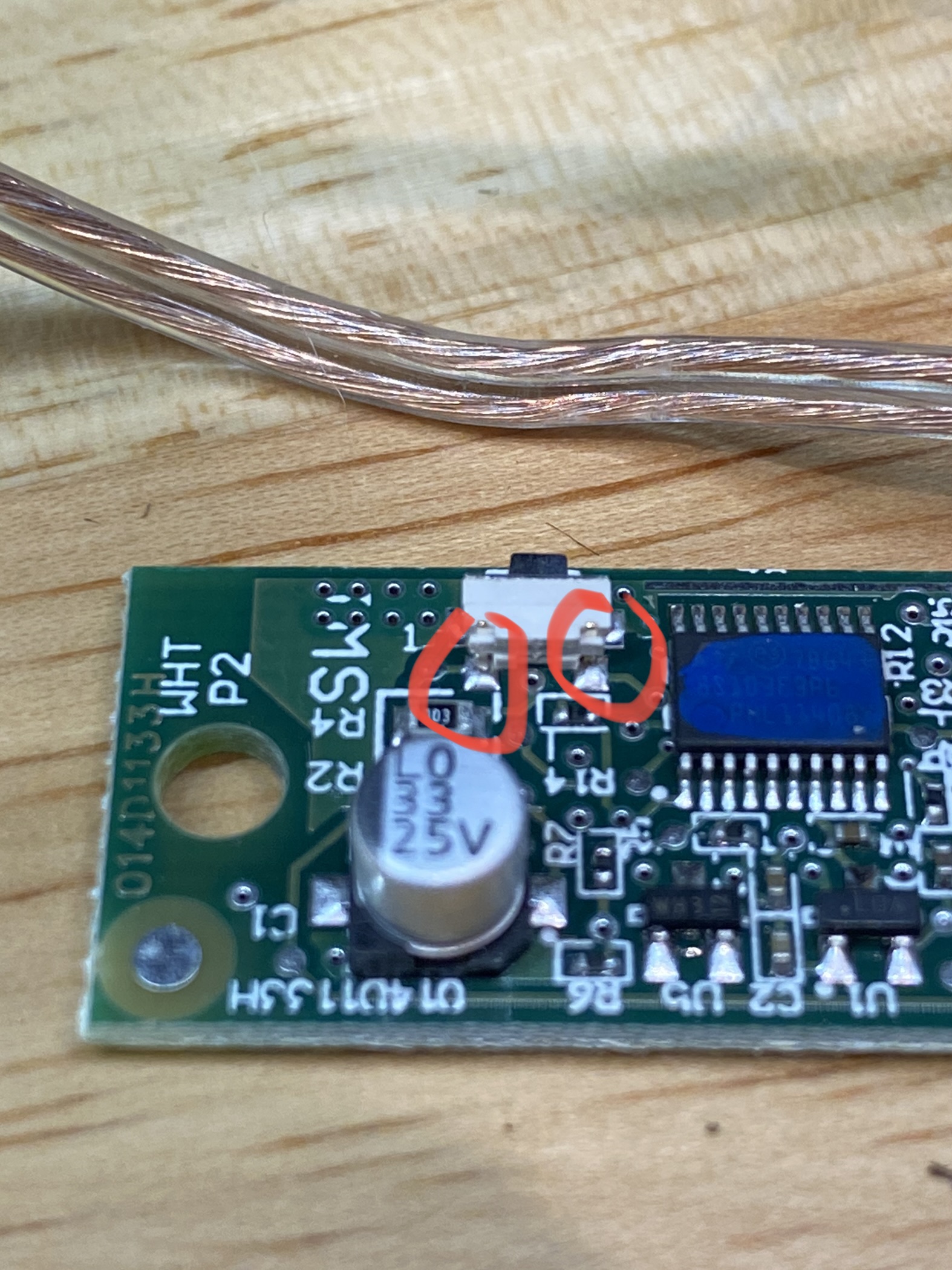
And to throw this out there for testing this process, while the button was connected to the GDO, I used a wire and touched these two spots with both ends of the wire and confirmed the light came on. Touched them again and the light turned off. So this validated I had the right points to solder the wires too as a dry contact relay basically connects the two.

1 Like

I know that feeling!

1 Like

I did not, but looking at it, it has open/opening/closed/closing/unknown - not sure if "stopped" would be unknown or if it would always show opening.

We really need a device driver that has a "stopped" state. Easy enough to determine if door was opening and never fully opened - it must be "stopped". With 2 contact sensors now I can certainly determine that.

3 Likes

Even though I have a v1 SmartThings contact/acceleration sensor on my door, I had only set this app to use the contact sensor and didn't include the "movement" sensor capability of it. I just tested it and analyzed the code, what happens if movement is determined and the door is closed, the state of the virtual garage door gets set to "opening" and if the door is open it gets set to "closing". It will stay in the "*ing" state until the contact is updated to say it is open or closed - so just another state in between open/closed.

I haven't used the other solutions and "thinking" outloud here, you could implement something similar and add a new input for number of seconds it takes to open/close the door. Then have a scheduled job trigger when it is in this "*ing" state and if the door is still in that status longer than that input set the status to stopped.

I wish I had added wire(s) for the light before I mounted it on the GDO, but there still is the issue that the best you can do is "toggle" the light rather than explicit on/off.

By the way, I strongly suspect you don't really need to solder two wires to the light pushbutton - just one. One of the two is almost certainly common with one of the two wires for the garage door toggle button. You can look at the PCB routes to determine or ohm it out. This point might be useful if you intend to run wire to a relay not at the GDO itself.

1 Like

I subscribe to Rboy's apps and drivers. Are you using the Garage Door Manager Open/Close Automatically with Timers or the Virtual Garage Door Manager?

This one: Virtual Garage Door Manager and Controller

Very true but my plan is to disable all "automatic" light options such as motion and the safety sensor turning it on. I will then use a Hue motion for Lux and motion along with a Aeotec Motion Sensor 6 in the ceiling to turn it on. I could also put in a rule to check lux of the room at night to ensure its off. Definitely trickier than explicitly knowing its on but it is manageable with the equipment I have in the garage.

2 Likes

Did I misunderstand this worked well with HE? I'm getting errors when trying to install the driver. The following is one example.

Metadata Error: Capability 'rboyapps.vacation' not found. on line 46

It does work but there are some differences you will work through. FWIW I have been on HE since March 2018 so my versions of his code are obviously very old as a result. Just looked and I am using v01.02.00 dated 2018-03-02

1 Like

I might have found a working solution for myself.

I've added fully open and fully closed contact sensors - fairly definitive for status.

I created a GV to determine whether my door is open, closed, moving (using multisensor acceleration), stopped, or invalid (both sensors closed).

The cancel and pushover are just there for testing.

Then using the GV I use RM to determine current status and if "open" is requested it will open if closed or stopped. If "close" is requested it will close if it is open or stopped. And I was able to add in an audible warning (using sonos in garage) and plan to add visual for closing (waiting for Zigbee colored bulb to arrive).

Then my arrival/departure/bedtime routines call the actions from these two vice calling garage open/close to the GDO.

Now I just have to depart/arrive a few times and see if it is stable. The multisensors are still being flakey on open/close status, not sure why, but it definitely messes with Zooz GDO (because Zooz relies on single sensor to determine status). Oh and I did switch back to Zooz GDO vice LGK - meh.

As always, I'm very open to any feedback - esp RM stuff - if there is better logic, I'm all for it.

2 Likes

What sensors are you using? I have a hard time finding good places for standard open/close (magnet) sensors on my door.

I'm using these:
AmazonSmile : tatoko Magnetic Reed Switch Normally Open Closed NC NO Door Alarm Window Security 6Sets : Electronics

Interestingly - i had to wire them NC/C to the Zen17 - would expect NO/C not sure why.

I nipped the ends off (where screws go) and used hot glue. Mounted a magnet on either side of the door puller then mounted the sensors at the top of the T-track where each lands at open/close. Then I used hot glue to hold the wires to the top of the T-track heading back to the GDO.

I still have to hook up the wireless transmitter to the relays. I am using these:
Sensors
Zigbee relay board
Wireless transmitter (paid more then I should have for someone else to solder 6 wires)
As it happens, my wife bought a wireless remote off Amazon for my daughter. She bought these:
After market remote (knock off) which come to about $9.50 each.

I'm using this app: Zooz garage door opener

I hope this helps someone researching this later.

2 Likes

Following the tips and advice from others in this discussion, I created my own Zigbee Garage Door Opener Device. I started by using a spare remote control for my Chamberlain MyQ garage door opener. I pulled out the circuit board as shown below:

Next, I purchase a Zigbee Relay Board from Amazon for $15 US.

Screen Shot 2021-09-18 at 5.38.16 AM

This board paired very easily with my HE hub. I configured this relay board to be in "inching" mode, which acts as a momentary relay switch (you turn it on, and 1 second later it turns off automatically). So the plan is to activate the push button on the garage remote control circuit board.

Next, I soldered two wires on the garage remote circuit board across the leads to the push button. Then, I inserted those leads in the Zigbee board's relay COM (Common) and NO (Normally Open) connections.

I then used some plastic electrical standoffs to position the remote control board on top of the relay board. Makes it very tidy.

Finally, I plugged in a micro USB cable into the relay board and put everything in a small electronic kit box, with the USB cable sticking out a hole in the box. I then velcroed this box under my office desk (where I've hidden a lot of my electrical devices) and plugged it into a USB adapter for power.

I can then turn on the switch for the relay device from my Hubitat Dashboard to activate the garage remote control. To make it even easier for me to trigger, I use the Android app called Macrodroid to trigger this device thru an HTTP request (using HE's Maker API) from my Galaxy Watch on my wrist. Really cool setup, thanks to all the great ideas and advice in this forum!

9 Likes

Love this! The only other step might be to add a USB battery adapter for the coin battery.

2 Likes