If you look inside the source code the Environment Sensor Device Driver, you will find the following section of code that makes use of the illuminance adjustment factor.
I see, adding a factor >= 1 complete changes the transfer function. Would be nice to know what the sensor was. I made a short attempt to find one that looks like the hardware without luck.
I believe he is using a TEMT6000 sensor. I would have thought he might have used an I2C sensor, since the BME280 is already I2C (unless he's using SPI?)
The sensor I use for light is TEMT60000 as mentioned by @ogiewon
In that datasheet, you will see a graph of how to convert current to lux value. The typical wiring diagram is to install 10K resistor at the emitter. My implementation is simply just read the ADC and use the ohm law to get the current. Then, I am using "Figure 1. Collector Light Current vs. Illuminance" to get the lux.
The BME280 is an expensive sensor. It is about $6 to $7 per sensor if you buy 10 unit or less in US. I do not think that there is a cheaper sensor than BME280. I do not want to skimp on sensor. I look somewhere else where I can get low cost to compensate for the sensor cost.
Please see the "MeasuredValue" as in this specification. The scale factor is just a number that divide the "MeasuredValue". They are not in Lux unit anymore. If you clear the factor setting in the preference, the DTH will go back doing the inverse calculation.
Now I'm curious and confused. Reading the Zigbee spec you linked it stated that the specification was for a "library", and it when on to state the transfer equation. Is that saying the library does the calculation? If not then its not clear why they go into so much detail.
Zigbee Cluster Libarary (aka ZCL) is not a library in the sense of library in c++ code.. I was confused as well when I looked into the document when I started learning about it.
ZCL is just specification. If you want to be compliant to do Illuminance Measurement, you have to send the value as in 4.2.2.2.1 MeasuredValue Attribute. ZCL is more like an RFC. It will tell you a bit in regard to their reasoning. "Where 1 lx <= Illuminance <=3.576 Mlx, corresponding to a MeasuredValue in the range 1 to 0xfffe".
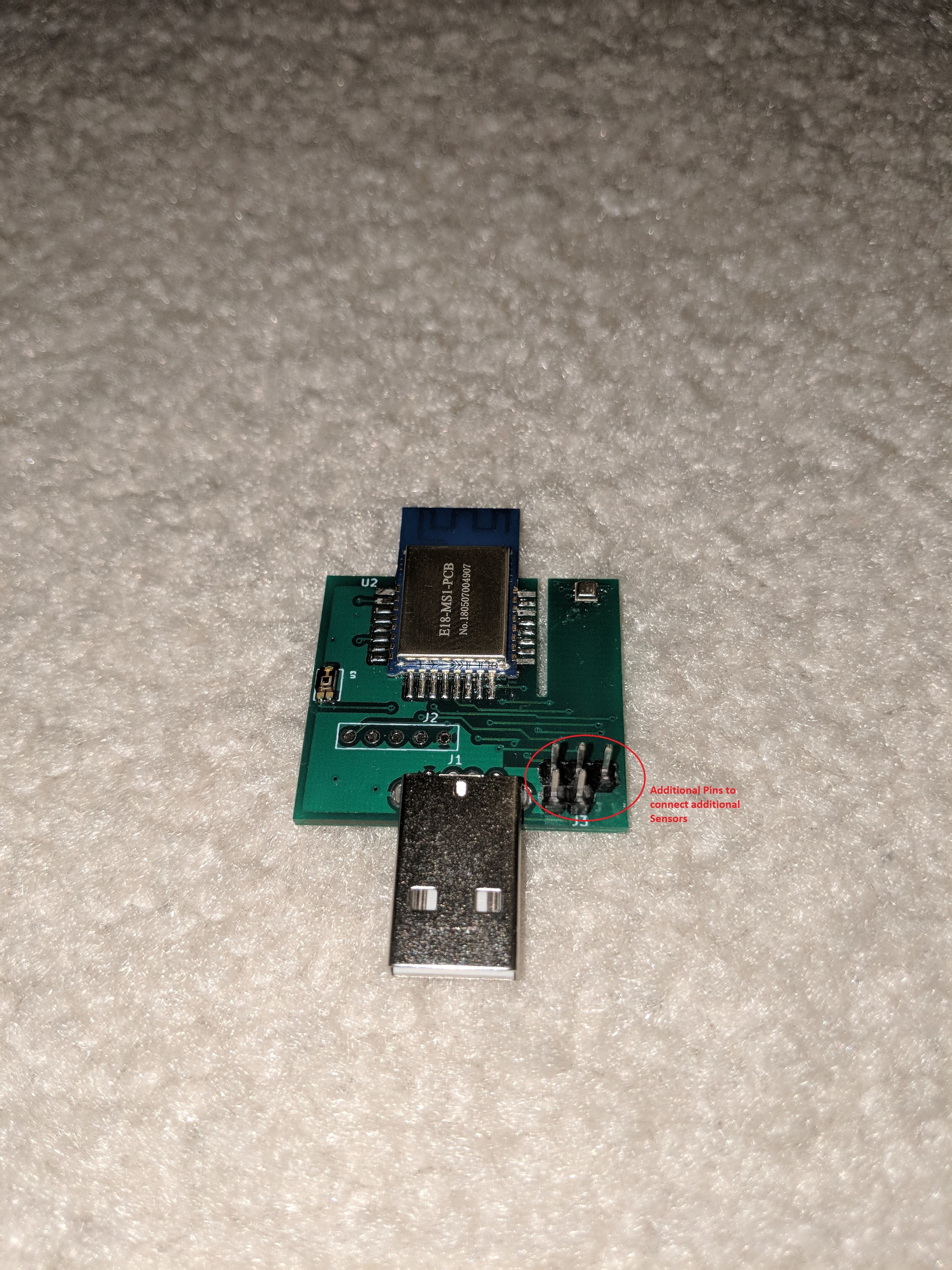
I just want to update my progress with this project. Having shared a few modules with community members here I started to get feedbacks. The most intriguing feedback is about being able to extend or expand the sensor.
In the past few weeks, I went back to drawing board and look for solution to accommodate the above. Here is what I come up with.
On the hardware side, the new board will expose analog, digital input and output pin. Access to 5 volt and 3.3 volt are also available.
On the firmware side, those pins are abstract out as Zigbee Basic Analog Input, Binary Input/ Output cluster. These clusters are accessible through Hubitat DH.
In layman terms, we will be able to access information from the sensors connected to the pin without needing to understand the lower level complexity of Zigbee protocol and Firmware development. Our DH will be getting one or zero from your digital sensor. Or, DH will be able to read your sensor Analog output in volt. Your DH can drive a thing using its digital output pin.
I have an example in the following video where I connect a moisture sensor, flame sensor and a relay.
I am very excited about this feature. I will have a few to share once I sort out and test them on my end. I will also share my experience connecting them with other sensors. I have motion sensor, Gas leak sensor , sound sensor in the queue.
Finally, this is still a Temperature, Humidity, Pressure and Light Sensor. It is still a Zigbee repeater to help with your Zigbee network. It is also help with your Xiaomi devices.
is it possible to add the sound sensor onboard? just having temperature, humidity, pressure, light and sound all onboard would be enormously helpful is this all-in-one compact unit.
once you add motion sensor support do you plan to also add case / mounting etc? without that placing these to capture motion will be a bit trickier - no?