I have notice that there are some interest among community member to monitor power loss. I was going to post some links. However, I found there are many good post about it. If you are interested, you can use the community search function.
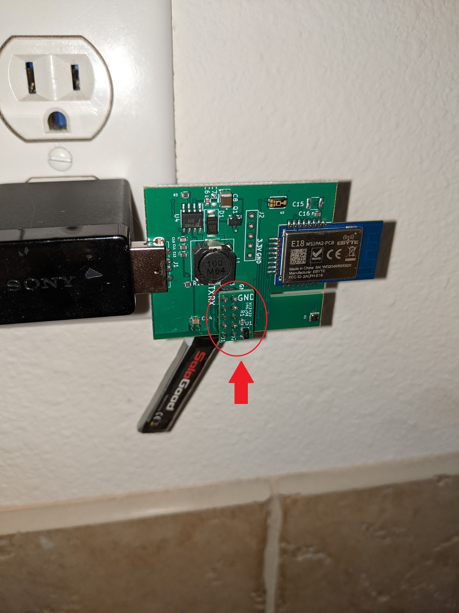
Today, I want to share a simple solution to monitor power loss using my sensor. This is an example of using the expand-ability of the sensor.
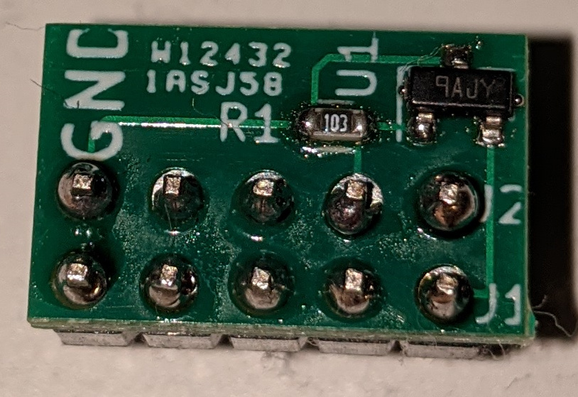
I make a simple circuit with a single resistor and voltage monitoring IC.
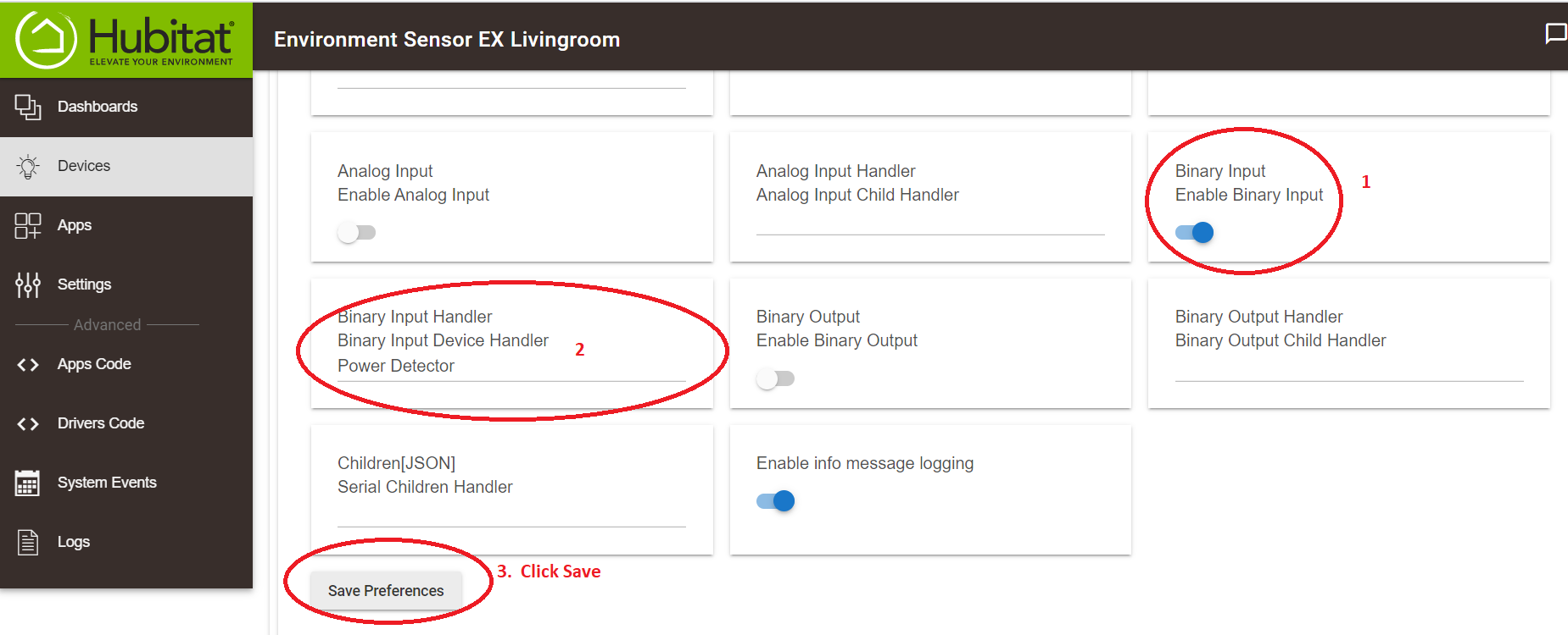
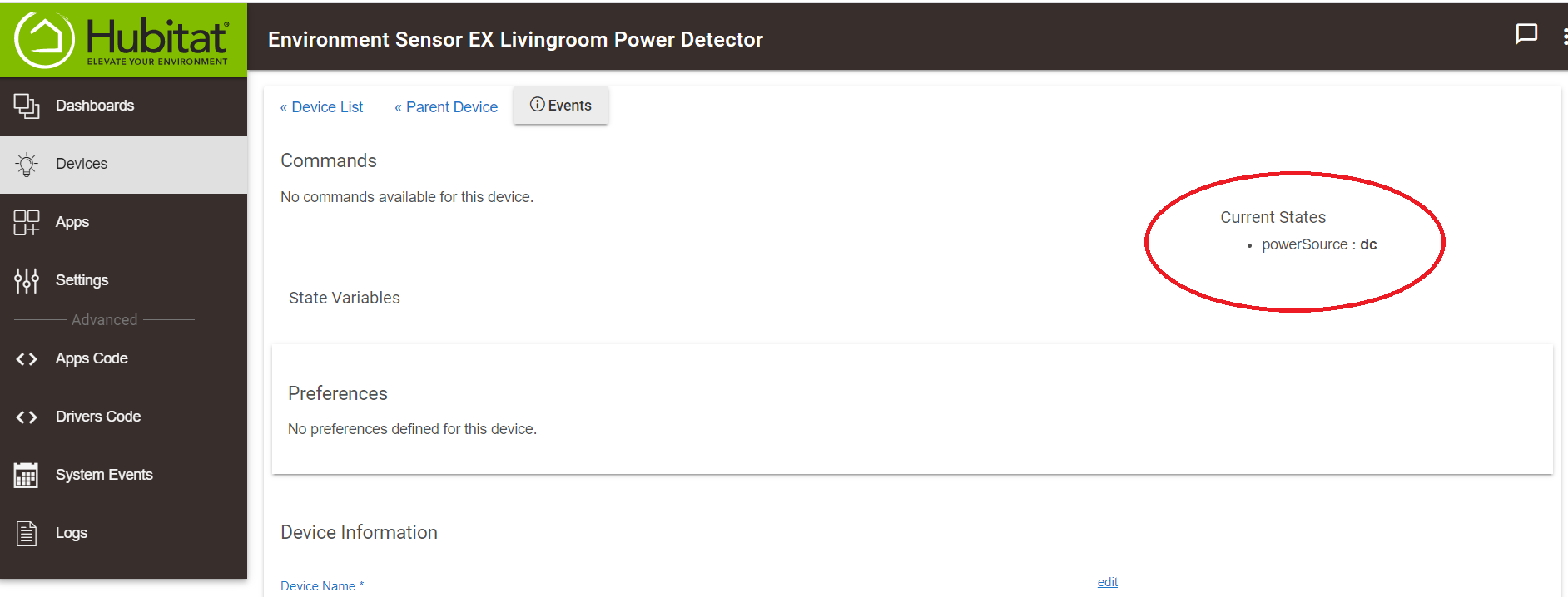
After that, you will a new device that will monitor whether the DC power to the sensor is down. You can use this to indicate power to the same segment you plugin the sensor to is down. You can use it in Rule machine to do anything you like.
I make 10 of the power monitoring circuit. I do not have a lot. I am going to give them as a bonus for those who purchase my sensor on Ebay. Please leave a note if you want one. I apologize for those who had purchased a sensor for me that I can't share it with you. The reason is the shipping cost will be more expensive than the cost of this circuit. But, please do send me your feedback whether you would be interested in such option. If I have gauge that there is enough demand, I could make the attachment circuit as an option to purchase. This should not be an expensive add on.
I hope it is an useful information for everyone. I think for some of us who already have the Environment running, adding a simple attachment that would get another useful information would be a big win.
@cwwilson08, I am sorry I was not clear on it. It is an attachment circuit. I can plugged it in for you before I ship it. I can even solder it for you as well to make it more permanent. Just leave me a note.
I personally do not solder it to make it permanent. I like to be able to easily unplug them in case in the future I need to access the expansion port other things. I am a bit different from most user. I keep developing and adding stuff on mine. There are plenty other functions on that expansion ports.
I seem to be having an issue with one of the sensors I got. I plugged it in today and it is telling me the temperature is 32 degrees, which it isn't. All other values are 0 except for RSSI is -31. It says DecryptFailure is 2, maybe that is a clue of what is up. Any thoughts? I have tried resetting per the instructions in this thread and removed from Hubitat and re-added but doesn't seem to change anything.
Yes, that seems look like a problem. Let's see if we can troubleshoot it. If we can't or it is an hardware issue, I can always replace it.
Please try other power adapter if you have extra. Power adapter is not build the same. Some can go bad. I just want to make sure that we have clean supply. I am aware that it is rather hard to do without test equipment. But, if you have other adapter, lets try it since it is not hard to do.
Another thing hopefully easy to do is to try to pair the sensor at different locations (not necessarily closer). Lets see if this can resolve the issue. Once paired, you can always try to bring the sensor to its intended location.
I would start with those 2 steps. If that does not work, we can try to replace the sensor. But, lets make sure before we jump to conclusion that it is an hardware issue. I sell small quantity of sensors. I tested each sensor that I shipped out.
Spot on. I thought of the same thing after I sent this message. I tried a power adapter that one of my other sensors is using successfully, reset the sensor again, re-paired with the Hubitat and it is working just fine again. I think I have a lot of old power adapters that I need to go through and throw out and replace with new ones. Thank you so much for the assistance!!
Thanks for letting me know and sharing with us the finding. Power supply that goes bad could have some impact on RF signal the the Zigbee radio need to generate. I have some capacitor and filter in the circuits to help to certain extend.
I also just have to share how much I truly love these things.
Since I have implemented them, I monitored them for a few days, tried different environmental changes to see how quickly they react to change and was very impressed. In the last couple of days, I have implemented rules for automatically setting my Mysa thermostats according to the sensors and I have also implemented rules to adjust my Hue lights based on the illuminance values of the sensors. All rules work perfectly and even better than I thought they would.
The living room always have the perfect amount of light based on sunlight from outside and auto-adjusting the lights in the room and my wife no longer complains that where she sits gets cold when the Mysas shut off at their set temperature! Thank you, thank you, thank you for an amazing product!
I've got a couple of these already but popped down an order for 5 more so I can monitor temp & humidity in more rooms now that we've moved and have room by room zoning with hydronic heating. If you've got a DC monitor circuit handy I'd love one.
I'll have to have a couple of the cases 3D printed, they look nice.
The new power loss circuit fundamentally work the same. It looked at the supply voltage and determine whether the supply is 5V (DC) or 3 to 4.2 V (Battery).
The difference is that I am using comparator IC and feed it to Digital input. The MCU will get interrupt when the digital pin change. On the link, it use Analog input which poll the voltage at settable interval.
At the end of the day, it is not much different. However, I am just making improvement. It should worked a little better compared to the old one.
Thank you for the purchase. I have attached the power monitoring add on to one of the module.
Let me know how it work for you. I would like to gauge the interest on the add on. If it is useful, I can make it as a part of the module. We would loose the digital input functionality.
Gotcha. Just wanted to let you know that this method is working very well. I get notified via the repeater for voltage drops (below 2.4v based on my install/resistor) before I get notified via my home generator (running Genmon w/ MQTT). Having a combination of both has proven well for addressing the zigbee bulbs in my home all coming on after an outage.
29 Oct 11:29:12 - [info] [hubitat device:Zigbee Repeater] AnalogInput: 2.440108
29 Oct 11:29:27 - [info] [debug:Generator MQTT] 241 V
29 Oct 11:30:01 - [info] [hubitat device:Zigbee Repeater] AnalogInput: 2.0121338
29 Oct 11:30:05 - [info] [debug:Generator MQTT] 0 V
29 Oct 11:30:05 - [info] [debug:Generator Outage?] Yes
29 Oct 11:30:07 - [info] [hubitat device:Zigbee Repeater] AnalogInput: 2.4347894
It also aligns with what APCUPSD tells me connected to mains:
2020-10-29 11:30:01 -0400  Power failure.
2020-10-29 11:30:04 -0400  Power is back. UPS running on mains.
Curious; what would be the expected current draw from these? and is there an efficiency difference between powering through USB vs the battery connector? Finally, what input voltage is tolerated on the battery connector if I were to power it there instead of USB?
Just playing with the first couple that I ordered; they're so much faster than my other sensors, and consistent from one to the next, which is definitely not the case with my Hue, Aeotec and Samsung sensors.
It should be around 117 mA ish. They are not constant. The current consumption can spike during transmission.
I am concern about powering through the battery connector. There is dedicated charger circuit that would push current when the USB is powered. That can cause issue for your source or other components. I would not recommend that. Having said that, in term of efficiency, I do not have the exact number. But, The charging IC would act as a boost DC to DC converter from voltage range between 2.7 and 4.2v to 5v dc output. These kind of boost converter is typically has very high efficiency (perhaps somewhere in the 90%). Could you share what you would like to do? Perhaps I may have options for you to choose.
Thanks for your feedback. I am happy that it work for you.
Reason I was asking is because I'd like to deploy one in my garage where I already have a bunch of 9vdc stuff, including a 5v boost/buck device to power some 5v relays. Since I already have 5vdc present, it would be super easy for me to wire this to the battery connector.
If that's a bad idea though, I'm sure I can either take a usb cable apart or find a usb to bare wire lead on Amazon, etc. to power it on the USB side.
I think this is the better way to go. The battery connector is controlled by a Lipo/Li-On battery charger. More importantly, you do not want to risk breaking your power source. The charger on my sensor will push current to the battery connector instead of sink the current if somehow the DC/USB side of the sensor is powered.
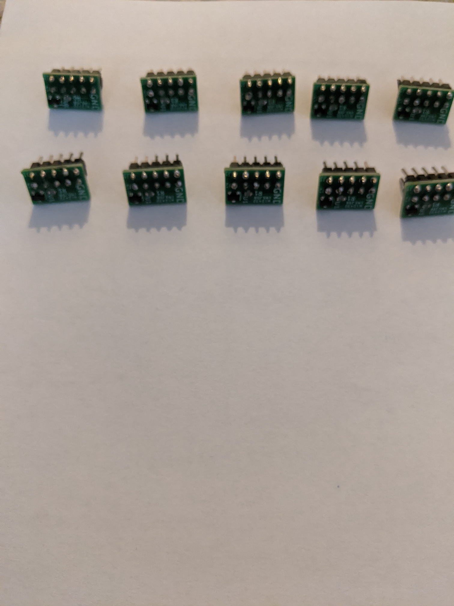
I just want to let everyone know that I still have some of the power monitoring available. I just make small quantity for all of to play around with it. If you like to try one, please leave a note to me. I will ship it out together with the Environment Sensor. It is free of charge while I still have them. I only have 10 left as in the picture above. For more information on how to add it to the hub, please take a look at below.