For everyone who will be getting this current batch, I want to mentioned that the battery connector is JST PH 2mm pitch. This should be common LIPO battery connector.
I want to briefly mention that please be careful in handling LIPO/Lithium Ion battery. Please do not connect them in the wrong polarity.
There is no standard on which side is positive or negative. In the board, there should mark for positive and negative side.
I tried this battery from Amazon.
The connector fit right and the polarity is correct out of the box on the above.
If you get a battery with wrong polarity, it is easy to reverse the side on the battery side of the connector. Here is a video on basically the concept on switching the polarity.
I think I mentioned to you about a way to detect power loss using the battery % attribute. This is the cleanest way to do it without any wiring needed. The issue is that it take sometime for the battery to drain even to 90% where you can use as indication that the sensor run on battery. Therefore, the main power which power the DC adapter is assumed down.
Here is way that I can think of with there minimal modification, we can detect power loss a lot faster. I want to share this with everyone else.
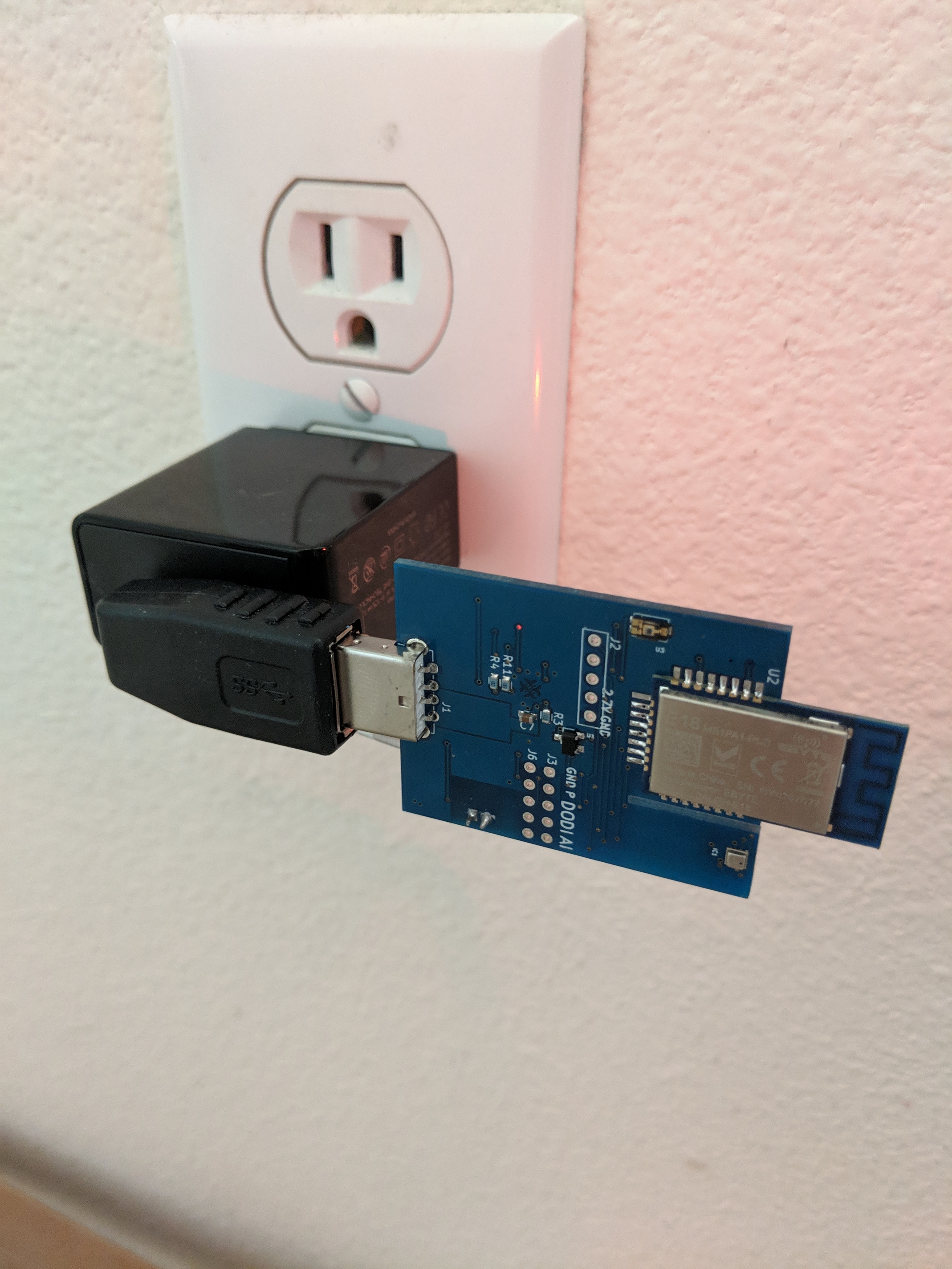
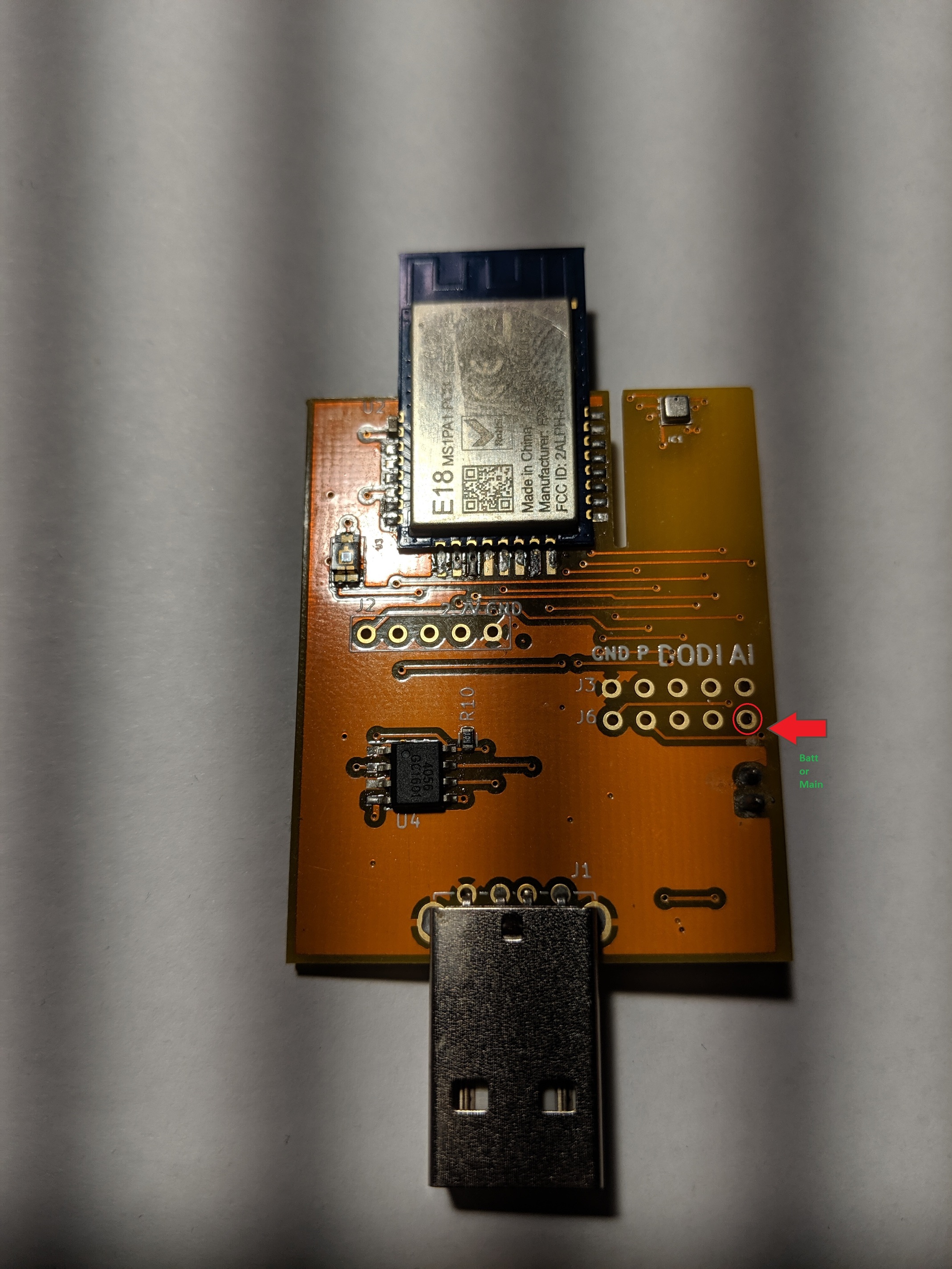
With the latest modules, there is a pin that connected to a switch that automatically connect to DC and switch to Battery when the DC power is lost.
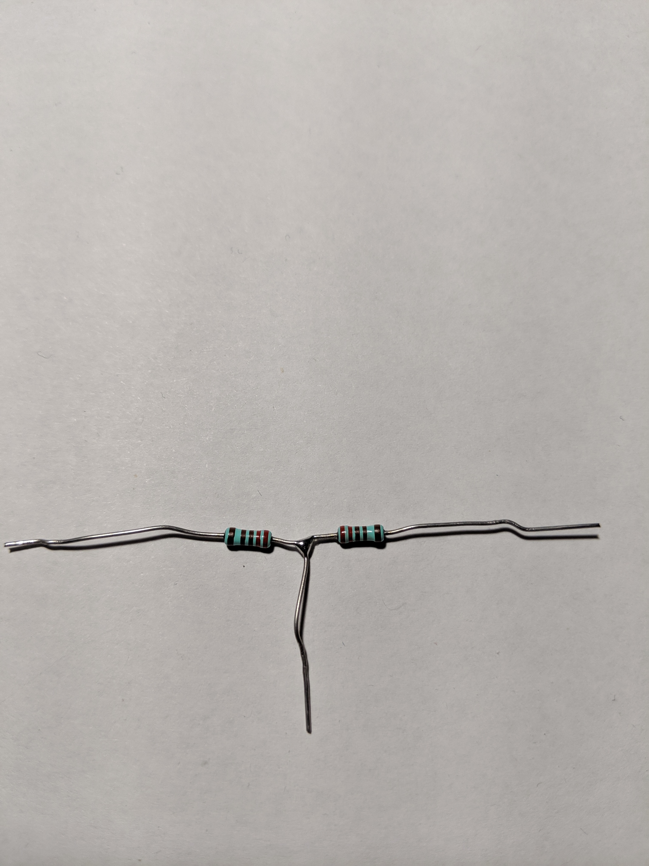
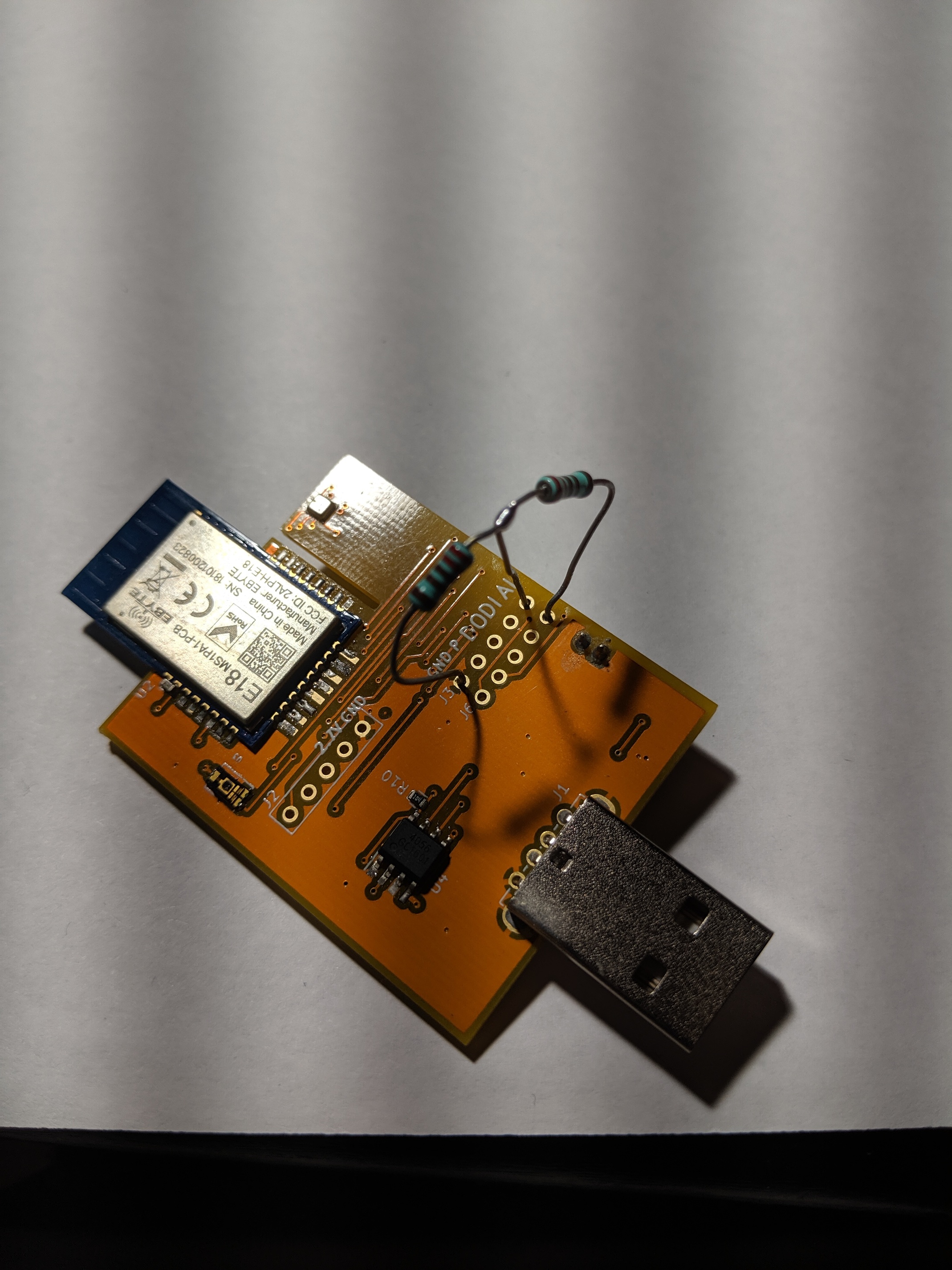
The idea is to connect this pin to analog input pin. However, we cannot connect them directly. We need to divide the voltage since the MCU work on lower voltage. You would need something like below.
Basically, my plan is to write a child device driver that read the voltage value on that pin using the analog input. I will translate them to PowerSource capability. If I see voltage above 4.6v, I will assume that the main DC power is working. If I see voltage below 4.3v, I will assume the device run on battery. With this assumption, we should be able to tell whether your main power is down or not.
I will write the DTH this weekend and share it on my github.
Very cool! I assume you could likely detect the voltage drop before the capacitors in the power supply fully depleted? Assuming a battery isn’t installed, could we measure the voltage change upon power returning to initiate the same sort of trigger (run rule based on power returning vs losing power). Can you tell me which resistors you’re using so I can wire this up myself? Thanks!
I would not count on this. Most of the capacitor have small value. The purpose are for decoupling rather than as reservoir. I would get small battery like I bought above from amazon. That will give you plenty of buffer.
Sorry, I forget to mention that any resistor between 1k to 10k should be fine for this purposes. I would not go above 30k.
(adding @JohnRob) If you just want to know whether the sensor comes back from power down on a module without battery, there is a "hack" if you would not be using the digital output. Here it is. You can turn on the digital output and install my Switch DTH on the device setting page. You may not need to modify the sensor at all. What you would do is to set notification that the power just come back on when the switch is set to turn on.
You can then set a rule or manually turn the switch off. Either way should be minimal work since I do not expect that you loose power every often.
You can also query the ResetCount. Unfortunately, this attribute is not proactively report-able. You have to issue a refresh to get the value updated. An increase in count from the last value read mean that you just had power down. Using the switch hack by itself is fine if you do not have some user in the house that mistakenly turn on and off the switch. Having both information should get you quite reliable detection.
You can add this DTH from the device setting page by turn in on the Analog input. You also need to enter the child DTH name "PowerSource". You can use the new child device in your rule machine to detect power loss.
Here are the possible value.
"battery", The power is detected running on battery. We are reading 3.0 to 4.4 v on analog input.
"dc", The power is detected running on DC. We are reading 4.4 v or above on analog input.
"mains", we will not be using this. We are assuming the DC is powered by main.
"unknown" We are reading 3.0v or below on analog input. If you are reading this value, you can use it to assume that the battery is running on fume. It is about to be cut off from the circuit.
You will need those resistors divider if you want to use this DTH.
Sorry, back on this subject again since my original detection method using an esp01 device doesn’t appear to work during a quick power blink - I’m assuming the power adapter doesn’t power down long enough to empty the capacitors, thus the esp01 device doesn’t reboot - which would trigger a refresh on my canary bulb if it did.
So would your above method be any different? If the power just blinks/dims and comes right back, then I assume it would be just as difficult to determine if power flickered using your device.
My other thought would be to install your device beside my canary bulb and measure illuminance, then trigger a refresh to the canary, which then turns resets the bulbs. Guess I’d need a battery to do that. Thoughts?
Btw, does your device charge the battery?
I also tried your child DTH above, it should be named "PowerDetector" not "PowerSource" as you indicated. It also shows "unknown" (I don't have a battery, and haven't added the resistors).
Do you have any idea the duration of the blink? Is it in mili-seconds range?
For a few seconds power blink, I think the esp and my solution above would work.
If you are looking to detect very short (mili-seconds or faster) AC drop, things could get complicated real quick. I would look into current sensor to do this. Typically, they will have enough bandwidth to detect an AC power drop.
Yes. My device only work with recharge-able LIPO or LI-ON battery. Please do not use non rechargeable battery.
Hard to say, varies based on wind/storms. Guess I could just do a refresh through apcupsd.
2019-06-20 18:07:53 -0400 Power failure.
2019-06-20 18:07:56 -0400 Power is back. UPS running on mains.
2019-06-20 18:08:05 -0400 Power failure.
2019-06-20 18:08:08 -0400 Power is back. UPS running on mains.
2019-06-20 18:08:22 -0400 Power failure.
2019-06-20 18:08:24 -0400 Power is back. UPS running on mains.
2019-06-20 18:13:05 -0400 Power failure.
2019-06-20 18:13:07 -0400 Power is back. UPS running on mains.
2019-06-20 18:13:36 -0400 Power failure.
2019-06-20 18:13:38 -0400 Power is back. UPS running on mains.
2019-06-20 18:13:47 -0400 Power failure.
2019-06-20 18:13:49 -0400 Power is back. UPS running on mains.
2019-06-20 18:14:01 -0400 Power failure.
2019-06-20 18:14:02 -0400 Power is back. UPS running on mains.
It seems some of the power blink is quite short like the last one.
2019-06-20 18:14:01 -0400 Power failure.
2019-06-20 18:14:02 -0400 Power is back. UPS running on mains.
With the rounding error, I do not know whether they are in the mili-seconds duration.
I would give the method that I gave you using analog input a try. I think that It could catch most of it. I would pick older power adapter. I have a few new power adapter from Amazon. They have huge capacitor in it. It could run my sensor for 2 seconds easily after it is unplugged. A lot of older cell phone adapter does not have huge capacitor I believe.
Let me look also an option where you can use the digital input. Let see what I can come up with.
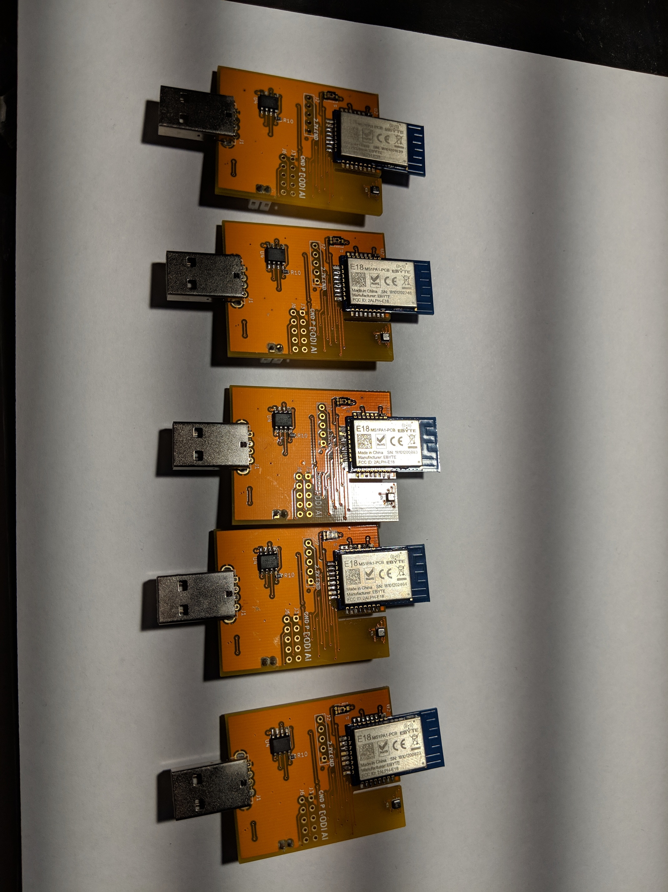
I just want to let everyone know that a have a few batch made that are ready to share.
Using this module, you will get an Xiaomi compatible repeater. When a xiaomi sleepy end device connect through my module, this module speak Zigbee 3.0 fully to understand the xiaomi request. This would allow xiaomi to maintain its connectivity. There is a lot of mention about Xbee compatibility to Xiaomi devices. Older S2XX version of Xbee is not a Zigbee 3.0. It maintains Xiaomi compatibility by setting default aging period for very long time.
It is battery backed up (optional, you do not have to use battery). This feature is important for me and most of us. Obviously, when the AC power is out, your hub and battery powered devices may still be running. If a compatible repeater went out, an Xiaomi child device may look for a different repeater which may not be compatible with it. The battery backup will allow the child maintain its route to this repeater in the case of power outage.
It has temperature, humidity, pressure sensor from dedicated Bosch BME280. Bosch made one of the best environment sensor today. It also come with one of the fastest light sensor.
The module is expand-able to drive one digital output. You can control a relay with it. It also come with one digital input and one analog input. The module has 3.3v and 5v pin to power small external sensors.
Nice, man. Please PM me details of how I can get hold of one or two.
I’ll need to find a “home expense” to apply them too.
Oh, and are reported values in metric ??
Cheers,
I forget to mention that these modules are fitted with Extended range Zigbee radio. I have standardized my order to this type of radio to simplify my process. The vendor claim 1 Km range on these radios due to additional amplifier chip. I believe that they are much less than that specification in home setting with wall around. However, they can penetrate these wall much better than non amplified radio.
In the past, I offered an external antenna modules. I have stop doing so because there is not a lot of interest on it. If anyone needs one, please let me know I will be happy to order some of them in the future batch.
I've just set the first module up and it appears the temperature is not overly accurate. I assume the drivers listed above on github are the latest. Would be good to have the latest drivers linked in the first post I would have thought.
I will do more testing with other sensors and report back, but it has made me wonder if its possible to get a decimal point for the temperature. If I need to calibrate (hoping the values are repeatable) it would be good to do so with a decimal point, or at least 0.5 degrees c resolution.
The other thing that may have been good was to have the sensor for illuminance a little taller on the board so if I manage to find a suitable case (or make one) then the sensor sits flush and not blocked (without requiring a large opening) by the case.
Yes it is the latest driver. It is a good suggestion. I will link it to the first post.
Do you have a picture how you install the sensor?
Please look at post 481. There is a small square silver component. It should be oriented at the bottom. It should also be perpendicular to the room air flow. These are recommendations. You do not need to follow it exactly. However, the exposure heat from the radio can be minimize following the suggestion. Therefore, you will get a better reading out of the box. A final calibration may still be wanted for further precission by adjusting the offset for temperature in driver page.
The decimal point is in the data. The GUI just does not show it. You can turn on logging. This will give you 2 decimal point of the temperature value which you can use for calibration.
Just wanted to drop in and say this works really well for my application - I mostly needed a real-time mains powered ambient light sensor. The fact that this doubles as a strong zigbee repeater is a bonus!
Now to figure out a 3D printed enclosure without messing up the light sensor part of it.,.