I did not realize this... I have stayed away from all other zigbee devices since I have so many Xiaomi sensors. I have feared that they would act as routers and mess up my Xiaomis.
I have 2 Iris plugs and the Xiaomi will not repeat through them so I am not using them.
Thanks Ogiewon, My reason is exactly the same as Brian's, I have a ton of Xiaomi devices and avoid zigbee bulbs like the plague, having read of so much pain with them(outside of Sengleds). I only got the cree after reading Iman's story with the sensor pairing through the bulb, and being unable to locate a GE bulb for a fair price.
The sensor paired immediately with the bulb, however sensor never reports any data and then falls off within minutes.
The bulb is going back to home depot, as it seems the sensor has a bad voltage regulator which should hopefully solve pairing issues, once i replace the regulator, and also solve the non commincation issue
So replacing that tiny voltage regulator did the trick. I also examined the board with a microscope and found a very small amount of solder bridging the 2 center legs of an 8 leg component, I cleaned that up with desoldering wick, replaced the voltage regulator, and the sensor paired and is reporting.
Thanks Iman for all your help
Just Fyi. These pins are fine to be bridged. Those pairs if pin infact are bridged on the trace. This component is double cmos that the battery protection chip used to cut off battery power when it detect over/under voltage of the battery.
Is there any other indication that it has a bad regulator other than not being able to pair it?
I finally got around to working on the analog SPL meter we talked about some time back, and the sensor won't pair, tried an FRS on it as well...
I just want to update you guys what I have from the latest batch I have to share.
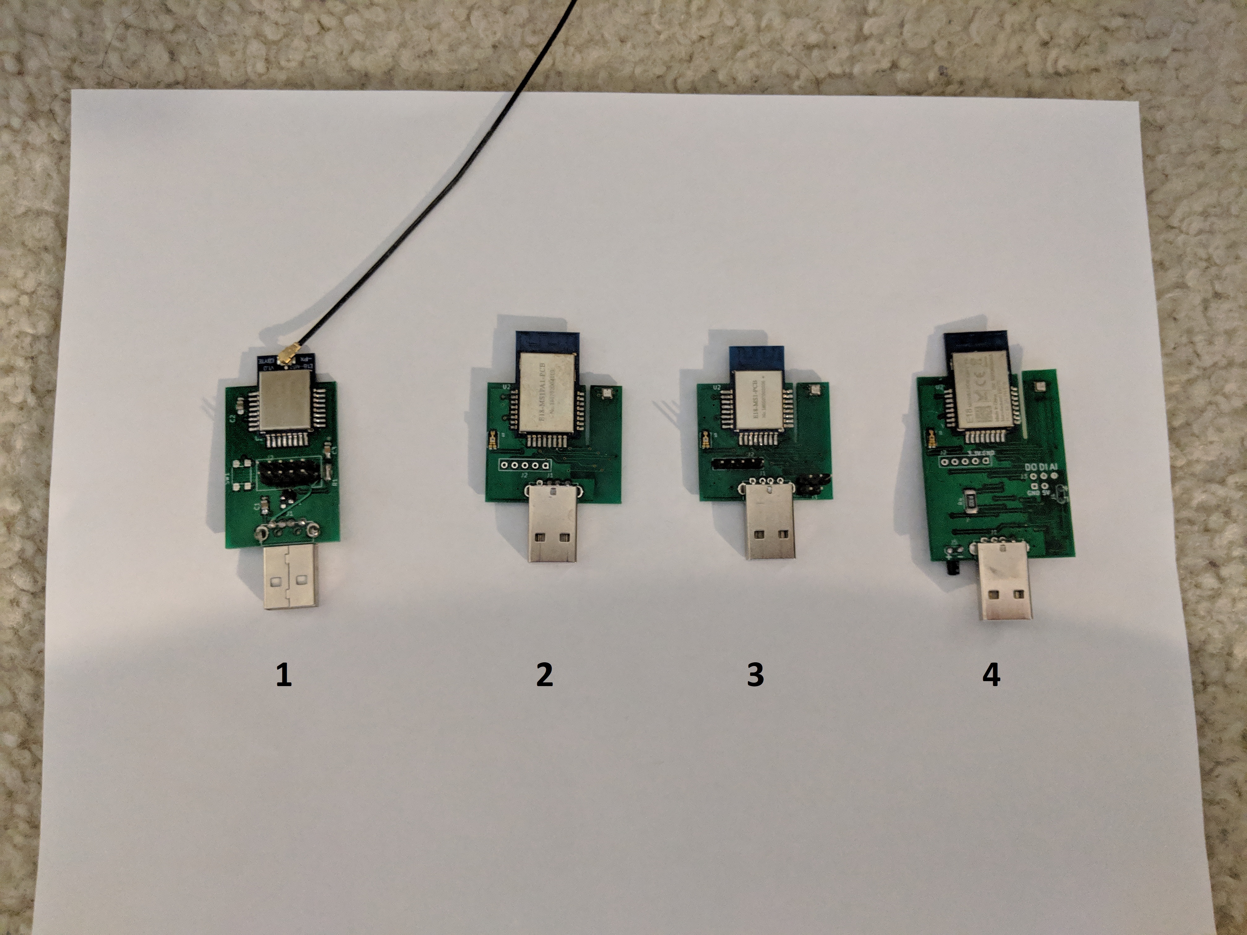
I only have one more smaller module (variant 1). It is time to share the bigger module that can take 18650 battery. As comparison, here is a picture that I took.
The bigger battery will give you a longer backup time. They should last at least about 20 hours. Battery is not included. Please get yourself a high quality 18650. The module has battery protection circuit. If you are getting a Panasonic NCR18650, you can opt one without battery protection. I have never try with a protected battery. They should work just fine.
Pm me if you are interested on trying these bigger modules.
Hello, I have one of your early boards and I have to say its been as solid performer. I've paired it once and since then I've had it off for a period of time, back on, moved it around and it just works. Very impressed.
Early on I though I read a post where you were considering opening up some pins to allow other sensors to be connected. I haven't been able to find it but I'm very interested.
Have you considered any sort of digital inputs? I would love one with 2 (or more) digital inputs in any form (i.e. needs closure to ground etc). I don't know if others would find this useful.
@JohnRob, thanks for your feedback and support on this project.
Since the latest 2 iterations of the module that I made have access to one digital input and output. It also support one analog input.
They are exposed as Binary Input/Output and Analog Cluster in zigbee world. This is what the Dth will be talking through to get access to the pins. I can give you more detail on this if needed.
If you need 2 digital pin, I suppose the analog input can be interpreted as digital level.
Let me know when you are ready. In the meantime, if you can share what sort of sensor would you be interested on connecting, I may be able to double check whether the idea should work.
The long story is I have an LG washer and dryer. Both are nearly 10 years old. As an option I purchased a Remote monitor. It would sit on a table upstairs and report the remaining washer and dryer times. Really helpful
I've gone through one set already and the 2nd one failed 3 weeks ago. They communicate through a power line modem (similar to X-10).
My plan is to cannibalize the PLModems on the appliances and tap into the data lines. My goal would be to simply know if they are running or not. I do not plan on spending the time to decode the data. Then using an opto-isolator and likely a filter I would pass that signal to your digital or analog inputs. Really very simple. I just have to pull one of the modems apart and look at the signals with a scope.
Washer and Dryer monitoring seems to be popular thing to monitor.
A while back, I have play around CT sensor. It is a current transformer sensor. It is much less intrusive than tapping the appliance circuity. The basic idea is here.
I do not apply it to measure the energy consumption. I use the sine wave output and look at it to determine a Legacy appliance consuming electricity or not hence, whether it is on or off. I play around using hacked audio detector sensor to get a digital signal. I also tried the circuit on the link and connect them to analog input. I write a simple DTH which monitor voltage changes. Here is a demo.
Further tuning to make it more reliable can be done. The above is just a proof of concept. I suppose we can design much better electronic if enough people want it.
This should be able to monitor your washer and dryer. vibration sensor could work if you can get proper tune of the sensitivity.
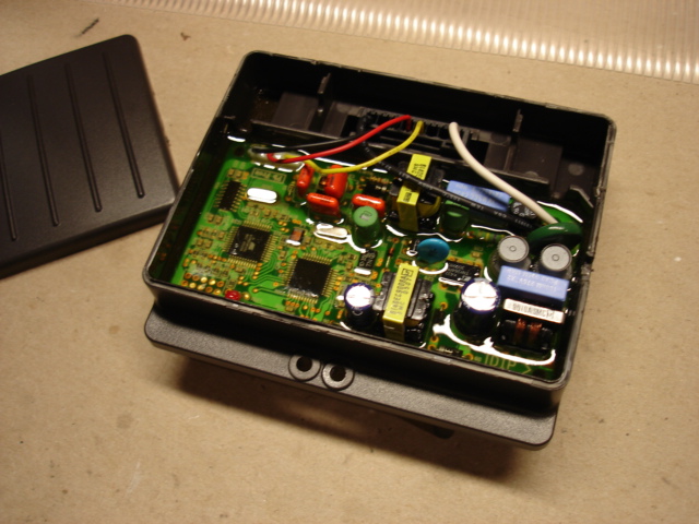
Thanks for the suggestion. However these appliances have an external PLC Modem plugged into the rear of the appliance.
I took one apart and I can see the V+(red) data(yellow) and gnd(black). I simply have to pull some of the guts out to make room for a FET and opto isolator then I should be good to go.
But first I do need to look at the signals and verify the are usable. I do have the wiring diagram / schematic from the service manual.
I have been meaning to recap what we have done with the module/sensor project in 2018. I want to thanks to community members here with your feedback and donation.
This is the first module that I shared with the community. It is just a simple Zigbee Repeater.
In the second iteration, the module gains Temperature, Humidity, Pressure and Light sensor.
The next improvement, the module allow user to add additional sensor or component through exposed Digital Input/Output pin and Analog Input.
In latest iteration, as we are closing out the year 2018, the module add battery backup
Through out these iterations, I try to focus on adding feature to improve our experience with our Smart Home. In summary, here are highlights of what we have so far.
A Zigbee 3.0 repeaters(routers) compatible with Major Zigbee devices in the market. (work nicely with Xiaomi devices).
An Environmental Sensor for your room with reliable and prompt reporting sensor reading.
Expand-able module with additional sensor for DIY-er.
Battery backed up module that combine the best of both world of battery operated sensor and dc powered sensor.
Moving forward, I want to share what I think a good investment for the project. I would like to optimize the parts and board design. In turn, I would like to make more consistent build across modules. I also would like to see whether we can scale the build to higher quantity.
Again, I want to thanks everyone for the feedback. For those who take risk on this project and donate, I really appreciate it. My goal is to build a working module on every steps for all of us.
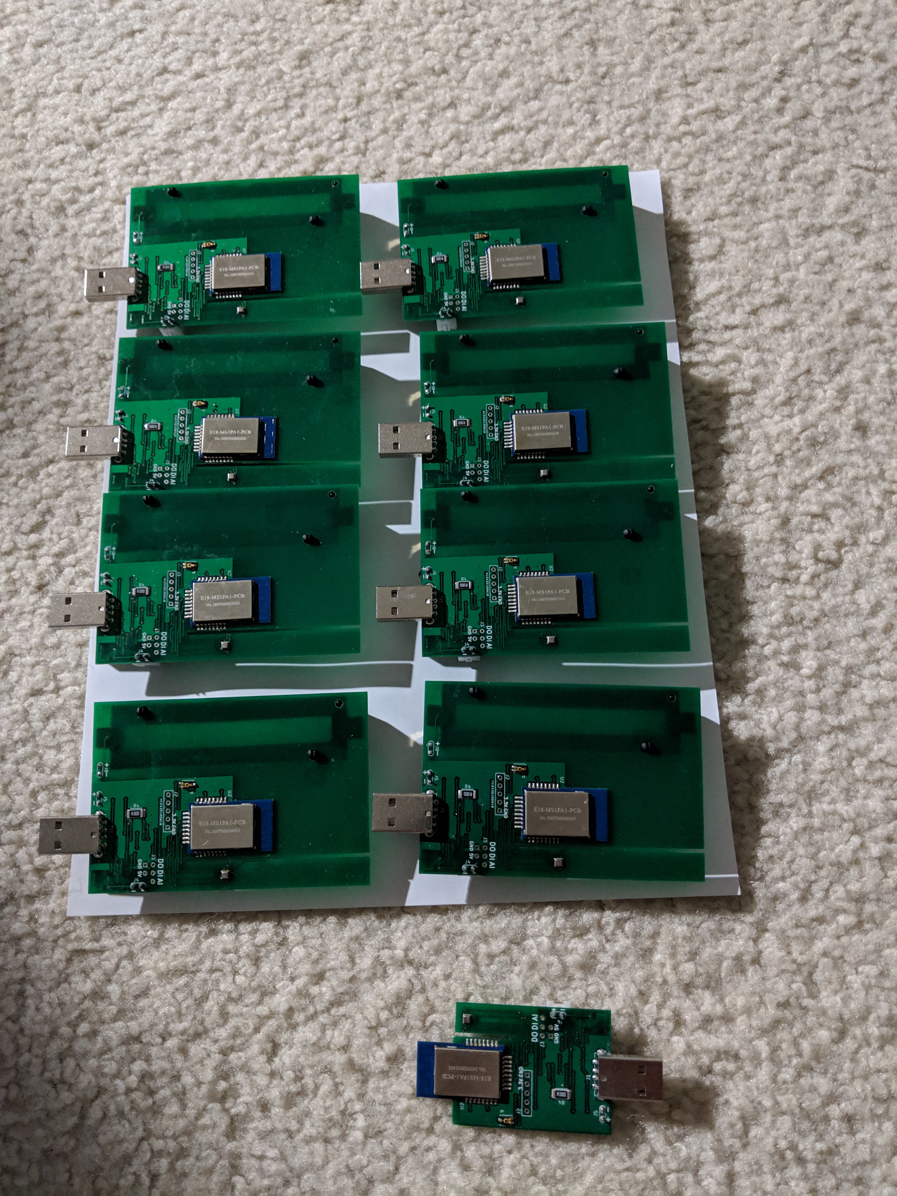
Just want to update everyone that I do not have the small module to share anymore. I still have six of the bigger (with 18650 battery case) module left.
For those out there considering to buy some of these. I just migrated from ST to hubitat. In the process I setup two of Iman's routers along with 3 Ikea outlets. I got the 5 "routers" in place before I started to pair all of my 30 Xiaomi sensors.
I have been running solid since Saturday and I finally had a chance to setup my xbee to scan the mesh. As it turns out, one of Iman's routers has 19 Xiaomi's, the other has 7.
As for the Ikea outlets. Outlet A, has 2 Xiaomis, Outlet B has 0, Outlet C has 0.
The remaining Xiaomi sensors paired to the hub directly.
The Ikea outlets are evenly distributed through my two story. One of Iman's is up in a far corner of my 2nd story, the other is in the opposite corner in my garage. So if anything the Ikea outlets should have had a better chance of picking up children.
Considering Iman's new routers can have a battery, I would say your MUCH better off purchasing them over the Ikea outlets. Unless you truely plan to control something with the Ikea Outlet.

 !
!