Hubitat with Homemade Temperature, Humidity, Pressure and Light sensor

Pretty easy to find with a search of this topic:

Can you hook up a temp probe to this? I need to measure lake temperature.
Thanks
Mike

@mjruotolo, yes... the modules can be fitted with external temperature probe. There is a couple option to go with this. One of them is using Arduino like below.

Another way is using the analog input of this sensor with K-type thermocouple module like below.

I helped a couple members here who happen to measure lake temperature. I think the ds18b20 is more agile since it can be wired with a long wire. When you narrow down your choice, I can help you with it.

I have both of these the one that is in the lake is using the DS18D20, I have the lake temp forwarded to several others via text and it is announced by Alexa in the morning.

If I could figure out how to do it I would also use this module with this water level sensor, Water Level Sensors

1 Like

Hi Everyone,

It has been a while since I have made an update here. This project is still going. I am still spending time to improve the Environment Sensor. If you follow this project, the latest sensor that we are supporting is BME680. BME680 add gas sensing on top of the Temperature, Humidity and Pressure. It is nice to know some aspect of the room in term of VOC, CO2 level as they can be dangerous.

Today, I am adding support to PMSA003 sensor. PMSA003 is a low cost dust sensor (or, is likely a small particle sensor). Monitoring small particle is something that I am interested on. Some of these particles may be unhealthy.

Supporting the BME680 and PMSA003 showcase the serial expansion capability of the Environment sensor. The environment sensor comes with UART ports where you can add Arduino and use the Environment sensor similar to ThingShield.

Here is a photo of my prototype unit.

The sensor above will show up like below in the Hubitat.

I am not going to bored you with the Power Detector and BME680 devices as the detail for those are here. The PMSA003 readings will show up like below.

I plan to build and design PCB which will integrate the PMSA003 in some future time as the project goes on. I am making these variants of Environment Sensor as a roadmap of what we can do with it. As pictured, I have a single module monitoring whether my room has power. I can open and close my curtain based light reading, I can control my HVAC based on current temperature, humidity, air quality of my room. It is a Zigbee repeater as well to help me build my Zigbee network. And now, I can do more knowing whether I have dusty room.

Anyway, I want to thank everyone here for their support. I am able to do these projects because of the help of many of you by purchasing my released Environment Sensor in Ebay.

Thanks
Iman

7 Likes

Like many of us with MYQ garage door, I am affected by changes in their cloud that caused the MYQ integration stopped working.

I found a solution inspired by some member here to take MQY integration local like the following thread.

If you have time to go through the above thread, you will find lot of good and detailed information to solve the issue. I personally picked a solution that simulate button press using an existing remote. A switch device in hubitat will be created to represent the button. Using this switch device, you can follow the thread there that there are sets of applications that you can use to complete the solution that give you a garage door device.

What is unique with what I am doing with the switch is that I want to eliminate the need for a relay. Most of the solution presented in the above thread require a dry contact relay. Eliminating the relay is possible since the button on the remote is a typical GPIO mechanism. Based on my understanding, the button roughly is as follow.

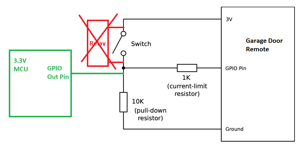
The idea is just connect a GPIO output from a 3.3V MCU straight to the button GPIO pin of a remote. This should have the same effect as shorting the switch to the 3V source.

Another twist that I did is to remove the battery and power the garage door remote from the 3.3V source of the MCU. The voltage difference is so small It would not break the garage door.

Here a prototype using the Environment Sensor digital output to test the ide. You will see that there are only 3 wires needed for power and a single gpio.

Google Photos

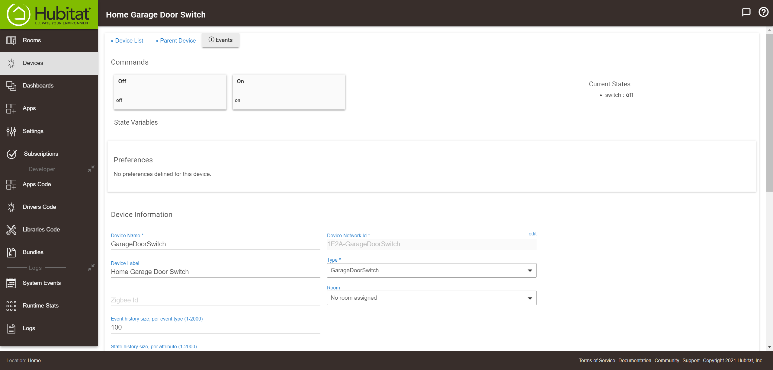
The switch will look like below.

Just FYI, this is just prototype to share my idea. My plan is to use an Arduino as expansion to the environment sensor. One of the reason for this is that the remote control has 3 buttons that I would like to take advantage while the Environment sensor only have one. With Arduino, I can have access to a lot more GPIO. There is also technical reason where I would like to have the Arduino to handle the button toggling rather than involving the hub. I also have plan to integrate additional sensors that would make sense for our garage door.

At this point, I just want to present an alternative which may be simpler for some of us.

Thanks
Iman

3 Likes

It resembles the ISS! :wink:

3 Likes

I just want to update everyone here that over the weekend moved the garage door solution using Arduino to support 3 buttons.

In the past, I have made an Environment Sensor that is in the form of Arduino UNO shield.

I soldered an Garage door remote to Arduino shield prototype board.

The last parts needed is an Arduino UNO. Just FYI, I am using a clone with WAVGAT brand. This looked like Arduino UNO R3. It is not exactly the same. The WAVGAT run on 3.3V (not 5V).

Here is how it look like stacked together.

Here is a short video clicking the button 3.

The Arduino is overkill just to help pressing the button. There are many GPIO ports that is still free to use. I am also planning to add more and more sensor to it. I have a motion sensor connected to it and AC power detection to it.

Thanks
Iman

5 Likes

I just add a few more sensors. I think they will be the final set of device/sensors that I have integrated. I will be installing it this coming weekend in my garage. Here are the final set of sensors. I just add a sets sensor/device to address some safety aspect of the garage door. I added the smoke sensor and a beeper. It is inspired by the work done @manuelangelrivera with his garage door.

All of the above fit in the palm of your hand.

7 Likes

That thing is a monster lol

3 Likes

You need to 3d build a case for it

1 Like

I have 3d printer. It is a bad one. In combination with my poor mechanical skill, I never really gotten anything worth out of my 3d printer.

My plan for this specific project is to let it install bare for now. I know that the Environment Sensor need to have exposure to the air. The light sensor need a clear enclosure.

Eventually, YES, I would like to have a case. Some of those clear food container case may have to do. I have not find any project enclosure that is clear case. If anyone have suggestion, please let me know. This project need the environment exposure. Some sensors really need air flow.

Just an update... I have installed my garage door controller. While setting up the contact sensors, I have another idea to use it as rotary encoder instead of detecting the just the "fully" open and close position.

I posted the demo on another thread. If you missed the demo, Here it is.

I think I would add a detail on how I did this here. The technique is not new. I uses a couple reed switch with a magnet. I install the magnet on my GD pully like below.

image.

As the magnet approach the reed switch, I am able to count the position of the garage door. I do need to start from a known position. This is easy to do. I uses fully closed position as 0. The 2 reed switches are needed because I want to know the direction. As the magnet approach the switch, the first switch that is closed first will tell me the direction. The basic principal is as simple as detecting which of the 2 switch closed first and deduce from that the direction of the move. Also, as the event happen, I count up or down depending on the direction. That is pretty much it.

FYI, here is the location of the pully that I use.

I was worried prior to testing this about the accuracy of the encoder. It really depend on the sequence of the contacts closing and opening to get it right. In the end. I am surprised how well it works. It is also have huge tolerance. The installation of the reed switches do not have to be very precise. The magnet does not need to be aligned precisely. My thinking is that the rotation is very slow. Therefore, the encoder does have a lot of flexibility.

I started looking for MYQ replacement. I think with the other stuff that I can fit on the board, I got much more than what MYQ can give.

3 Likes

Brilliant! And I can use this whereas my other ideas have hit major hurdles. Thanks, Iman.

1 Like

What is the recommended way to remove dust from this? Also, will a lightdim have any adverse effects?

I do not remove dust on mine. It has not giving me any issue. All components on the module is safe to wash. The only sensor that is not washable is BME280. This is the temperature, humidity and pressure sensor. It require air flow therefore it will always exposed to dust. I have seen any degradation on mine so far. Perhaps, if you expose it in unusually high dust area, it could experience issue. Any sensor like this will have issue as they need air flow to do its work. Now, you can use membrane to enclose the sensor. I have nor seen any manufactures that does this for consumer use.

I am not quite understand about this. The light has negligible impact to the longevity of the module. If you imply that dark area is humid, BME280 is one of the best sensor that take care of humidity drift available in the market. I know that many other sensor have manual heater that you have to control to reduce humidity accumulation. BME280 could have handle the automatic heater internally. As developer, we do not need to do anything.

Thanks. It will get a lot of fine feather dust from my amazon and cockatoo. Can I hit it with compressed air from a distance?

The Lightdims I was referring to are dark translucent film stickers meant to darken LEDs. Specifically I want to know if there are any components near the LED that I need to be careful not to cover with such a sticker.

It is a neat approach to the problem.
However, reed switches are notorious for their unreliability. I have worked with tons of them in that past and they fail at the worst times. I don't design with them at all now.
A better choice would be a shaft position encoder. There are all kinds of them. They are simple and VERY reliable. It can be as simple as a coded tape on the shaft of the pulley hub to a digital encoder connected to your pulley shaft.
I have two rollup doors on my horse barn that I will be adding encoders to for the same purpose as you. This way I can tell exactly how far open the doors are at anytime. We leave them slightly ajar periodically for ventilation but close them at night.
Hope this helps.

3 Likes

Everything the modules except the bme280 should be able to handle the blow from compressed air. We are of course not defining the pressure. But, I am assuming that it is typical cleaning blower. The air flow on the BME280 is quite small. I can see that small particle could potentially enter the sensor and accumulate. However, this would take a long time and small particle. I am not sure feather dust from bird is small enough. If you are concern about it, BME280 mentions about using membrane. I have never tried to enclose my sensor with a membrane. I am just concern that it is a costly wrapper that would allow air and humidity pass through. This could get costly real quick.

I would not worry about this at all. The energy consume and translated to light is so small to have any issue.

I will see what mine will last for. I consider other options as well. But, I roll the dice and think that worst come worst the reed switches are maintenance item. We can track the usage and replace them before it failed. My primary goal is to use something simple for simple installation.

The next thing I consider was hall effect sensor. This does not break easily and use the same configuration. I did not go this route as each hall effect sensor need 3 wires (vcc,gnd and signal) vs the simple 2 wires. But, if you are looking for reliability, hall effect sensor as replacement is the way to go.

The shaft position is actually the inspiration for what I did. I study a relative encoder on how it works. I think it is simple enough to handle the signal by the hub. It is a very slow rotation anyway. I do not want to deal on doing the encoder mounting. So, my idea is to adapt the garage door pully as the encoder.