Hubduino Timing

@ogiewon

The original thread is extremely long so , decided to start new fresh one.
I created a Hubduino-based custom controller for the Autoslide (sliding door open/close actuator).
Everything is working almost fine but it looks like there is some timing related issues and I wonder
if this can be fixed right in Hubduino Sketch instead of adding a delays in RM
(Being experienced EE I hate the delay-based fixes for the problems).
Here is a Hubduino Sketch:

r for the //******************************************************************************************
// File: ST_Anything_Relays_ESP8266.ino
// Authors: Dan G Ogorchock & Daniel J Ogorchock (Father and Son)
//
// Summary: This Arduino Sketch, along with the ST_Anything library and the revised SmartThings
//          library, demonstrates the ability of one NodeMCU ESP8266 to
//          implement a multi input/output custom device for integration into SmartThings.
//
//          The ST_Anything library takes care of all of the work to schedule device updates
//          as well as all communications with the NodeMCU ESP8266’s WiFi.
//
//          ST_Anything_Relays_ESP8266 implements the following ST Capabilities as a demo of what is possible with a single NodeMCU ESP8266
//            - 3 x Relay Switch devices
//
//
// Change History:
//
//    Date        Who            What
//    ----        ---            ----
//    2015-01-03  Dan & Daniel   Original Creation
//    2017-02-12  Dan Ogorchock  Revised to use the new SMartThings v2.0 library
//    2017-04-17  Dan Ogorchock  New example showing use of Multiple device of same ST Capability
//                               used with new Parent/Child Device Handlers (i.e. Composite DH)
//    2017-05-25  Dan Ogorchock  Revised example sketch, taking into account limitations of NodeMCU GPIO pins
//    2017-11-27  Kai Lenk       Modified to 3 relaySwitch
//    2017-11-29  Dan Ogorchock  Revisions to make sure works for Kai Lenk
//    2018-02-09  Dan Ogorchock  Added support for Hubitat Elevation Hub
//
//******************************************************************************************
//******************************************************************************************
// SmartThings Library for ESP32WiFi
//******************************************************************************************
#include <SmartThingsESP32WiFi.h>

//******************************************************************************************
// ST_Anything Library
//******************************************************************************************
#include <Constants.h>         //Constants.h is designed to be modified by the end user to adjust behavior of the ST_Anything library
#include <Device.h>            //Generic Device Class, inherited by Sensor and Executor classes
#include <Sensor.h>            //Generic Sensor Class, typically provides data to ST Cloud (e.g. Temperature, Motion, etc…)
#include <Executor.h>          //Generic Executor Class, typically receives data from ST Cloud (e.g. Switch)
#include <InterruptSensor.h>   //Generic Interrupt "Sensor" Class, waits for change of state on digital input
#include <PollingSensor.h>     //Generic Polling "Sensor" Class, polls Arduino pins periodically
#include <Everything.h>        //Master Brain of ST_Anything library that ties everything together and performs ST Shield communications

#include <IS_Contact.h>        //Implements an Interrupt Sensor (IS) to monitor the status of a digital input pin
#include <EX_Switch.h>         //Implements an Executor (EX) via a digital output to a relay 
#include <S_TimedRelay.h>      //Implements a Sensor to control a digital output pin with timing capabilities
#include <EX_TimedRelayPair.h> //Implements an Executor to control a pair of digital output pins

//*************************************************************************************************

// WiFi Credentials
#include "credentials.h"

//*************************************************************************************************
//NodeMCU v1.0 ESP8266-12e Pin Definitions (makes it much easier as these match the board markings)
//*************************************************************************************************

//#define LED_BUILTIN 16
//#define BUILTIN_LED 16
//
//#define D0 16  //no internal pullup resistor
//#define D1  5
//#define D2  4
//#define D3  0  //must not be pulled low during power on/reset, toggles value during boot
//#define D4  2  //must not be pulled low during power on/reset, toggles value during boot
//#define D5 14
//#define D6 12
//#define D7 13
//#define D8 15  //must not be pulled high during power on/reset

// ESP32 WDOOM IO Pins
#define IN1   14
#define IN2   12
#define IN3   13

#define OUT1  25
#define OUT2  26
#define OUT3  23

//******************************************************************************************
//Define which Arduino Pins will be used for each device
//******************************************************************************************

#define PIN_CONTACT_1      IN1  //Hubitat Capabilities - DIO Pin (Normally Open!)
#define PIN_CONTACT_2      IN2  //Hubitat Capabilities - DIO Pin (Normally Open!)
#define PIN_CONTACT_3      IN3  //Hubitat Capabilities - DIO Pin (Normally Open!)

#define PIN_TIMEDRELAY_1   OUT1 //SmartThings Capability "Relay Switch"
#define PIN_TIMEDRELAY_2   OUT2 //SmartThings Capability "Relay Switch"
#define PIN_RELAY_1        OUT3 //SmartThings Capability "Relay Switch"

//******************************************************************************************
//ESP8266 WiFi Information
//******************************************************************************************
// Set your WiFi details so the board can connect to the WiFi and Internet

// Get Credentials from the credentials.h file
const char* str_ssid     = mySSID;
const char* str_password = myPASSWORD;

IPAddress ip        (192, 168,  20, 151);  // Device IP Address       //  <---You must edit this line!
IPAddress gateway   (192, 168,  20,   1);  // Router Gateway          //  <---You must edit this line!
IPAddress subnet    (255, 255, 255,   0);  // LAN Subnet Mask         //  <---You must edit this line!
IPAddress dnsserver (192, 168,  20,   1);  // DNS Server              //  <---You must edit this line!
const unsigned int  serverPort = 8090;     // Port to run the HTTP Server on

// Hubitat Hub TCP/IP Address
IPAddress hubIp     (192, 168, 20,   90);  // Hubitat Hub IP          //  <---You must edit this line!

// Hubitat Hub TCP/IP Address
const unsigned int hubPort = 39501;        // Hubitat Nub Port

//******************************************************************************************
//st::Everything::callOnMsgSend() optional callback routine.  This is a sniffer to monitor 
//    data being sent to ST.  This allows a user to act on data changes locally within the 
//    Arduino sktech.
//******************************************************************************************
void callback(const String &msg)
{
//  Serial.print(F("ST_Anything Callback: Sniffed data = "));
//  Serial.println(msg);
  
  //TODO:  Add local logic here to take action when a device's value/state is changed
  
  //Masquerade as the ThingShield to send data to the Arduino, as if from the ST Cloud (uncomment and edit following line)
  //st::receiveSmartString("Put your command here!");  //use same strings that the Device Handler would send
}

//******************************************************************************************
//Arduino Setup() routine
//******************************************************************************************
void setup()
{
  //******************************************************************************************
  //Declare each Device that is attached to the Arduino
  //  Notes: - For each device, there is typically a corresponding "tile" defined in your 
  //           SmartThings Device Hanlder Groovy code, except when using new COMPOSITE Device Handler
  //         - For details on each device's constructor arguments below, please refer to the 
  //           corresponding header (.h) and program (.cpp) files.
  //         - The name assigned to each device (1st argument below) must match the Groovy
  //           Device Handler names.  (Note: "temphumid" below is the exception to this rule
  //           as the DHT sensors produce both "temperature" and "humidity".  Data from that
  //           particular sensor is sent to the ST Hub in two separate updates, one for 
  //           "temperature" and one for "humidity")
  //         - The new Composite Device Handler is comprised of a Parent DH and various Child
  //           DH's.  The names used below MUST not be changed for the Automatic Creation of
  //           child devices to work properly.  Simply increment the number by +1 for each duplicate
  //           device (e.g. contact1, contact2, contact3, etc...)  You can rename the Child Devices
  //           to match your specific use case in the ST Phone Application.
  //******************************************************************************************
  
  //Polling Sensors
  
  //Interrupt Sensors
  // Name, IO Pin, Initial State, Internal Pullup, Number of Loop Counts 
  static st::IS_Contact   sensor1(F("contact1"), PIN_CONTACT_1, LOW, false, 500);
  static st::IS_Contact   sensor2(F("contact2"), PIN_CONTACT_2, LOW, false, 500);
  static st::IS_Contact   sensor3(F("contact3"), PIN_CONTACT_3, LOW, false, 500);

  //Special sensors/executors (uses portions of both polling and executor classes)
  static st::S_TimedRelay sensor4(F("relaySwitch1"), PIN_TIMEDRELAY_1, LOW, true, 1200, 0, 1, 0);
  static st::S_TimedRelay sensor5(F("relaySwitch2"), PIN_TIMEDRELAY_2, LOW, true, 1200, 0, 1, 0);

  //EX_Switch arguments(Name, Pin, Initial State, Invert Logic) change last 2 args as needed for your application 
  static st::EX_Switch executor1(F("switch1"), PIN_RELAY_1, HIGH, true);

  //*****************************************************************************
  //  Configure debug print output from each main class 
  //  -Note: Set these to "false" if using Hardware Serial on pins 0 & 1
  //         to prevent communication conflicts with the ST Shield communications
  //*****************************************************************************
  st::Everything::debug      = true;
  st::Executor::debug        = true;
  st::Device::debug          = true;
  st::PollingSensor::debug   = true;
  st::InterruptSensor::debug = true;

  //*****************************************************************************
  //Initialize the "Everything" Class
  //*****************************************************************************

  //Initialize the optional local callback routine (safe to comment out if not desired)
  st::Everything::callOnMsgSend = callback;
  
  //Create the SmartThings ESP32WiFi Communications Object
    //STATIC IP Assignment - Recommended
    st::Everything::SmartThing = new st::SmartThingsESP32WiFi(str_ssid, str_password, ip, gateway, subnet, dnsserver, serverPort, hubIp, hubPort, st::receiveSmartString);
 
    //DHCP IP Assigment - Must set your router's DHCP server to provice a static IP address for this device's MAC address
    //st::Everything::SmartThing = new st::SmartThingsESP8266WiFi(str_ssid, str_password, serverPort, hubIp, hubPort, st::receiveSmartString);

  //Run the Everything class' init() routine which establishes WiFi communications with SmartThings Hub
  st::Everything::init();
  
  //*****************************************************************************
  //Add each sensor to the "Everything" Class
  //*****************************************************************************
  st::Everything::addSensor(&sensor1);
  st::Everything::addSensor(&sensor2);
  st::Everything::addSensor(&sensor3);
  st::Everything::addSensor(&sensor4);
  st::Everything::addSensor(&sensor5);
  
  //*****************************************************************************
  //Add each executor to the "Everything" Class
  //*****************************************************************************
  st::Everything::addExecutor(&executor1);
   
  //*****************************************************************************
  //Initialize each of the devices which were added to the Everything Class
  //*****************************************************************************
  st::Everything::initDevices();
  
}

//******************************************************************************************
//Arduino Loop() routine
//******************************************************************************************
void loop()
{
  //*****************************************************************************
  //Execute the Everything run method which takes care of "Everything"
  //*****************************************************************************
  st::Everything::run();
}

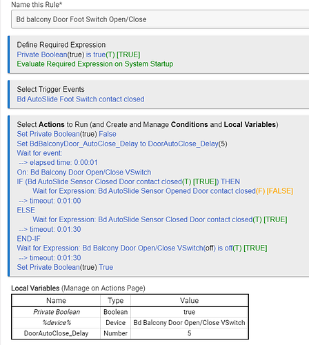
Here is a RM rule witch has timing related problem currently fixed with an added delay

The rule is triggered by physical Foot Switch connected to one out of 3 Hubduino
contact sensors. When rule is triggered it toggles virtual switch which triggers a dependent
RM rule. This one is actually sends a commands to the Autoslide actuator by toggling one of
two Hubduino relay-switch with 2sec auto off function. Without a 1 sec delay the log actually records on/off activity for the relay switch but physical Autoslide actuator ignores this command
(I am not sure if actual pulse was generated or it was too short). With the added 1 sec delay
things are working as expected however in both cases the Hubduino controller produces
"Connection reset" event in a log at exact time when on command was sent to the relay-switch.
My question is: Is it possible to fix this right in Arduino/Hubduino sketch?
The added delays are absolutely not welcome for fixing a problems.
Lots of things are possible inside the Arduino sketch, as long as one understands the underlying architecture.

If you can explain in very simple terms, exactly how you’d like the sketch to behave, I can provide guidance on how to change the sketch’s code.

One of my RM rule is triggered by Hubduino Contact Sensor and almost immediately
sends a command Switch On to back to Hubduino. With no extra delay in between
these two events Switch On command is entirely missing even log for switch says
it was toggled. Adding a delay (must be near 2 sec) fixes the problem. I really don't
like to fix a problems by adding a delays left and right. Ideally it will be nice if Hubduino
can provide a Ready status. In this case RM rule can check status before sending
something to Hubduino (basically will be waiting for Ready status).

Sorry, no ready status feature is coming anytime soon... :slight_smile:
However, if you'd like, the sketch could process the logic locally. When the contact sensor changes value, the sketch could automatically change the timedRelay device. This would take Hubitat out of the loop for performing the action, while still keeping Hubitat updated with the state changes of both devices. It would also still allow Hubitat to control the timedRelay device.

Would this be helpful?

Is this some sort of Hubduino architectural problem?

Well, no really helpful. I want to keep all logic in one place which is HE.
The related logic is only a little fraction of the entire Autoslide control algorithm.
BTW, I added this extra sensor just today and it happens to be a trigger for only
one also new RM rule. I guess, I have to live with my very lovely delay fix.
The rest works just fine because there are native delays between a sent comand and
after a while sensor response. There are 2 more contact sensors which never could
be triggered together (only one at a time).

It is some sort of race condition, but I am not sure if it exists on the microcontroller or Hubitat side of things (probably on the microcontroller, but I am not exactly sure where to look.) What microcontroller are you using to run the ST_Anything sketch? Older Arduino UNO or MEGA boards are really slow compared to ESP8266/ESP32 boards.

ESP32

Well, there goes that hypothesis... :thinking:

It is all open source. Feel free to dig through the code to see if you can identify the root cause.

I just simply don't have the time to dig into this issue right now.

Well, I am experienced EE with limited SW capabilities. Digging through the SW code
unfortunately is not my area of expertise.

@ogiewon

Hubduino misbehavior.
While updating my AutoSlide Hubduino Controller I replaced ESP8266 controller with ESP32
and added one more Contact Sensor. ESP8266 version worked basically flawlessly for more
than a year. New one based on ESP32 one has a lot of problems and basically near always
fails. The RM rule sends an On command to one relay-switch with auto Off function (1.2 sec).
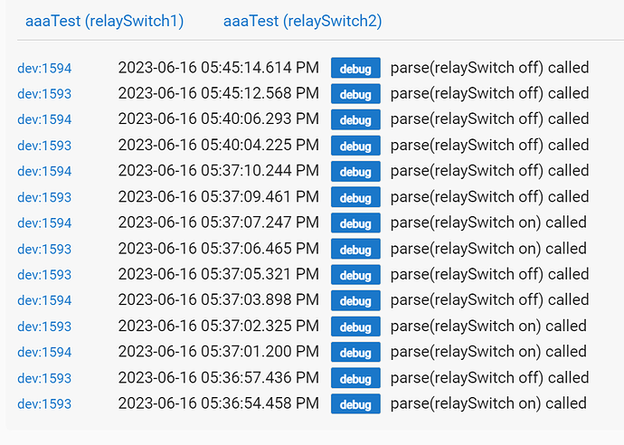
Here is a portion of the RM rule log (middle line):


At this time parent Hubduino device logs "Connection reset" (this is very consistent):
image
Correspondent child relay switch logs 3 entries starting with OFF command (strange):
image
And real physical output does not toggled.

Controlling child device from the Device page is always works as expected.

Any ideas what could be wrong (different device and as a result different libraries,
slightly different Arduino IDE, now it is 1.8.19)?
Sketch is basically the same with one more Contact Sensor added.

PS.
I am thinking to rewire my control board back for ESP8266.
Does this makes any sense?

I really don't have any idea what might be wrong. If using the ESP8266 results in better performance, then I would see that as a viable alternative to the ESP32.

I have been using both ESP8266 and ESP32 microcontrollers for years without any strange behaviors.

You may want to explore the use of ESPHome, as an alternative to HubDuino, to see if you have better results. ESPHome has a team of paid employees from Nabu Casa working on it, with regular releases.

If you want to use ESPHome devices with Hubitat, you have two options:

  1. There is a Hubitat Community integration for ESPHome
  2. Use ESPHome deives connected to an instance of Home Assistant. Then use the HE community HADB integration to bring those devices into Hubitat from Home Assistant.

If you can provide me with a very simple ESP32 ST_Anything sketch, along with the procedure on the Hubitat side to reliably reproduce the issue you are seeing, I will take a look and see if I can replicate the problem here. Currently, the somewhat small snippets of information you've provided to date do not really give me enough info to go on to try to set up a lab system here to try to reproduce the issue.

I am aware that trying to send rapid back to back Ethernet commands to the microcontroller will result in the second command being missed sometimes. Not sure there is too much I can do about that at this point, as I have already reproduced that particular issue, and I was unsuccessful in finding a fix for it.

The hope with any Open Source project is that others will help to enhance and improve the software. When my son and I wrote ST_Anything back in 2014/2015, we invested a massive amount of time to bring ST_Anything to fruition. These days, my son is busy with his full-time career and life interests. I have continued to make small tweaks here and there, and back in 2018 I spent a lot of time porting ST_Anything ST Groovy code over to HubDuino Hubitat Groovy drivers. Since I have already deployed my few instances of HubDuino/ST_Anything, and they are running without any issues, I am not really investing too much additional time into this effort. I am happy to continue to support it, but I just don't have the time or motivation to dig into obscure issues that only a single user has reported. Just trying to be honest and set your expectations of support for a free, open source project.

1 Like

First of all - BIG Thank you for all your support.
And yes, I clearly understand all your points.

There are two different factors involved for the problem I was observing.
First - In one place my RM was sending 2 commands back to back (thanks to my latest RM
"improvement"). Of course, the most important second command did not go through in many cases (but not all). The RM was fixed.
Second thing maybe Hubduino related.
In my previous version with ESP8266 and after migrating project to ESP32 I was using
two instances of "relay_switch" (the one with auto off function, i.e. momentary switch).
On the ESP32 and even with simple control from the device page (pushing on button)
the log always recorded warning for "Connection reset" event and for the device itself
"command off", "command on" and "command off" sequence. First "command off" makes
no sense. This behavior is very consistent and 100% reproducible. I am not sure was
it the same with ESP8266 because that older project worked 99.99% times. So, I simply
did not watch any related logs.
To cleanup my project I replaced "relay_switch" instances with common "switch".
I had to add the delayed OFF commands in RM but now all logs are clean and so far
everything works as expected (I hope, the preliminary testing was 100% successful).

At some point you may want to see why "relay_switch" produces "Connection reset"
event. But even if it is a real problem and you will fix it I am not planning to update
my project after.

Thanks again for all yours help and support.
Hubduino is very nice and extremely helpful project for HE.

1 Like

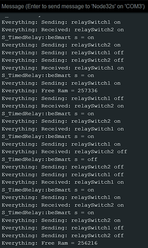
Okay - based on the above information, I fired up a NodeMCU ESP32 microcontroller, using Arduino IDE 2.1.0 and ESP32 Board Manager package v2.0.9. I used the ST_Anything_Multiples_ESP32WiFi.ino sketch as a starting point, and made sure there were two s_TimedRelay devices in the sketch. Everything compiled and was uploaded to the ESP32 board without any errors. I made sure to keep the Arduino IDE Serial Monitor window open to be able to see if there were any error messages produced.

I then opened up the Hubitat Logs in one window, and each of the two RelaySwitch devices in their own browser windows. I turned the devices on and off in every possible pattern I could imagine (letting the built-in s_TimedRelay timer expire and not letting it expire). I could never get any sort of failure to occur.

I wonder if you maybe chose a pin on the ESP32 that you should not have? Some pins are really not meant for end-user use, and can cause unexpected behaviors depending on how they are wired. I am using ESP32 GPIO pins 2 and 21 for my testing.

HubDuino Logs

Arduino Logs

Hope this helps you trouble the issue you're experiencing. Unfortunately, I cannot reproduce it here.

1 Like

Thank you for testing and taking your valuable time.
I reprogrammed the original board (this is ESP-WROOM-32 with 2 GND, VIN and V3.3 pins
near USB connector) with original sketch, created a Test Hubduino instance on HE and
repeated your test. I was almost ready to say "now I also cannot reproduce the problem"
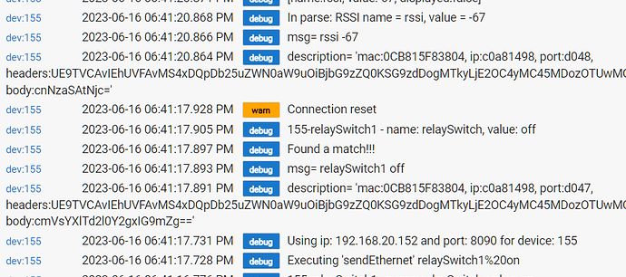
but suddenly got "Connection reset" warning:

So, unfortunately I was able to reproduce a problem but now it is very seldom vs in previous
case it was 100% repeatable. I don't know why I am getting different results before and now.
Everything is exactly the same: board itself, pinout, sketch and Arduino IDE (V1.8.19).
And just in case here is my sketch:

//******************************************************************************************
// File: ST_Anything_Relays_ESP8266.ino
// Authors: Dan G Ogorchock & Daniel J Ogorchock (Father and Son)
//
// Summary: This Arduino Sketch, along with the ST_Anything library and the revised SmartThings
//          library, demonstrates the ability of one NodeMCU ESP8266 to
//          implement a multi input/output custom device for integration into SmartThings.
//
//          The ST_Anything library takes care of all of the work to schedule device updates
//          as well as all communications with the NodeMCU ESP8266’s WiFi.
//
//          ST_Anything_Relays_ESP8266 implements the following ST Capabilities as a demo of what is possible with a single NodeMCU ESP8266
//            - 3 x Relay Switch devices
//
//
// Change History:
//
//    Date        Who            What
//    ----        ---            ----
//    2015-01-03  Dan & Daniel   Original Creation
//    2017-02-12  Dan Ogorchock  Revised to use the new SMartThings v2.0 library
//    2017-04-17  Dan Ogorchock  New example showing use of Multiple device of same ST Capability
//                               used with new Parent/Child Device Handlers (i.e. Composite DH)
//    2017-05-25  Dan Ogorchock  Revised example sketch, taking into account limitations of NodeMCU GPIO pins
//    2017-11-27  Kai Lenk       Modified to 3 relaySwitch
//    2017-11-29  Dan Ogorchock  Revisions to make sure works for Kai Lenk
//    2018-02-09  Dan Ogorchock  Added support for Hubitat Elevation Hub
//
//******************************************************************************************
//******************************************************************************************
// SmartThings Library for ESP32WiFi
//******************************************************************************************
#include <SmartThingsESP32WiFi.h>

//******************************************************************************************
// ST_Anything Library
//******************************************************************************************
#include <Constants.h>         //Constants.h is designed to be modified by the end user to adjust behavior of the ST_Anything library
#include <Device.h>            //Generic Device Class, inherited by Sensor and Executor classes
#include <Sensor.h>            //Generic Sensor Class, typically provides data to ST Cloud (e.g. Temperature, Motion, etc…)
#include <Executor.h>          //Generic Executor Class, typically receives data from ST Cloud (e.g. Switch)
#include <InterruptSensor.h>   //Generic Interrupt "Sensor" Class, waits for change of state on digital input
#include <PollingSensor.h>     //Generic Polling "Sensor" Class, polls Arduino pins periodically
#include <Everything.h>        //Master Brain of ST_Anything library that ties everything together and performs ST Shield communications

#include <IS_Contact.h>        //Implements an Interrupt Sensor (IS) to monitor the status of a digital input pin
#include <EX_Switch.h>         //Implements an Executor (EX) via a digital output to a relay 
#include <S_TimedRelay.h>      //Implements a Sensor to control a digital output pin with timing capabilities
#include <EX_TimedRelayPair.h> //Implements an Executor to control a pair of digital output pins

//*************************************************************************************************

// WiFi Credentials
#include "credentials.h"

//*************************************************************************************************
//NodeMCU v1.0 ESP8266-12e Pin Definitions (makes it much easier as these match the board markings)
//*************************************************************************************************

//#define LED_BUILTIN 16
//#define BUILTIN_LED 16
//
//#define D0 16  //no internal pullup resistor
//#define D1  5
//#define D2  4
//#define D3  0  //must not be pulled low during power on/reset, toggles value during boot
//#define D4  2  //must not be pulled low during power on/reset, toggles value during boot
//#define D5 14
//#define D6 12
//#define D7 13
//#define D8 15  //must not be pulled high during power on/reset

// ESP32 WDOOM IO Pins
#define IN1   14
#define IN2   12
#define IN3   13

#define OUT1  25
#define OUT2  26
#define OUT3  23

//******************************************************************************************
//Define which Arduino Pins will be used for each device
//******************************************************************************************

#define PIN_CONTACT_1      IN1  //Hubitat Capabilities - DIO Pin (Normally Open!)
#define PIN_CONTACT_2      IN2  //Hubitat Capabilities - DIO Pin (Normally Open!)
#define PIN_CONTACT_3      IN3  //Hubitat Capabilities - DIO Pin (Normally Open!)

#define PIN_TIMEDRELAY_1   OUT1 //SmartThings Capability "Relay Switch"
#define PIN_TIMEDRELAY_2   OUT2 //SmartThings Capability "Relay Switch"
#define PIN_RELAY_1        OUT3 //SmartThings Capability "Relay Switch"

//******************************************************************************************
//ESP8266 WiFi Information
//******************************************************************************************
// Set your WiFi details so the board can connect to the WiFi and Internet

// Get Credentials from the credentials.h file
const char* str_ssid     = mySSID;
const char* str_password = myPASSWORD;

IPAddress ip        (192, 168,  20, 152);  // Device IP Address       //  <---You must edit this line!
IPAddress gateway   (192, 168,  20,   1);  // Router Gateway          //  <---You must edit this line!
IPAddress subnet    (255, 255, 255,   0);  // LAN Subnet Mask         //  <---You must edit this line!
IPAddress dnsserver (192, 168,  20,   1);  // DNS Server              //  <---You must edit this line!
const unsigned int  serverPort = 8090;     // Port to run the HTTP Server on

// Hubitat Hub TCP/IP Address
IPAddress hubIp     (192, 168, 20,   90);  // Hubitat Hub IP          //  <---You must edit this line!

// Hubitat Hub TCP/IP Address
const unsigned int hubPort = 39501;        // Hubitat Nub Port

//******************************************************************************************
//st::Everything::callOnMsgSend() optional callback routine.  This is a sniffer to monitor 
//    data being sent to ST.  This allows a user to act on data changes locally within the 
//    Arduino sktech.
//******************************************************************************************
void callback(const String &msg)
{
//  Serial.print(F("ST_Anything Callback: Sniffed data = "));
//  Serial.println(msg);
  
  //TODO:  Add local logic here to take action when a device's value/state is changed
  
  //Masquerade as the ThingShield to send data to the Arduino, as if from the ST Cloud (uncomment and edit following line)
  //st::receiveSmartString("Put your command here!");  //use same strings that the Device Handler would send
}

//******************************************************************************************
//Arduino Setup() routine
//******************************************************************************************
void setup()
{
  //******************************************************************************************
  //Declare each Device that is attached to the Arduino
  //  Notes: - For each device, there is typically a corresponding "tile" defined in your 
  //           SmartThings Device Hanlder Groovy code, except when using new COMPOSITE Device Handler
  //         - For details on each device's constructor arguments below, please refer to the 
  //           corresponding header (.h) and program (.cpp) files.
  //         - The name assigned to each device (1st argument below) must match the Groovy
  //           Device Handler names.  (Note: "temphumid" below is the exception to this rule
  //           as the DHT sensors produce both "temperature" and "humidity".  Data from that
  //           particular sensor is sent to the ST Hub in two separate updates, one for 
  //           "temperature" and one for "humidity")
  //         - The new Composite Device Handler is comprised of a Parent DH and various Child
  //           DH's.  The names used below MUST not be changed for the Automatic Creation of
  //           child devices to work properly.  Simply increment the number by +1 for each duplicate
  //           device (e.g. contact1, contact2, contact3, etc...)  You can rename the Child Devices
  //           to match your specific use case in the ST Phone Application.
  //******************************************************************************************
  
  //Polling Sensors
  
  //Interrupt Sensors
  // Name, IO Pin, Initial State, Internal Pullup, Number of Loop Counts 
  static st::IS_Contact   sensor1(F("contact1"), PIN_CONTACT_1, LOW, false, 500);
  static st::IS_Contact   sensor2(F("contact2"), PIN_CONTACT_2, LOW, false, 500);
  static st::IS_Contact   sensor3(F("contact3"), PIN_CONTACT_3, LOW, false, 500);

  //Special sensors/executors (uses portions of both polling and executor classes)
  static st::S_TimedRelay sensor4(F("relaySwitch1"), PIN_TIMEDRELAY_1, LOW, true, 1200, 0, 1, 0);
  static st::S_TimedRelay sensor5(F("relaySwitch2"), PIN_TIMEDRELAY_2, LOW, true, 1200, 0, 1, 0);

  //EX_Switch arguments(Name, Pin, Initial State, Invert Logic) change last 2 args as needed for your application 
  static st::EX_Switch executor1(F("switch1"), PIN_RELAY_1,      HIGH, true);
  //static st::EX_Switch executor2(F("switch2"), PIN_TIMEDRELAY_1, LOW,  true);
  //static st::EX_Switch executor3(F("switch3"), PIN_TIMEDRELAY_2, LOW,  true);

  //*****************************************************************************
  //  Configure debug print output from each main class 
  //  -Note: Set these to "false" if using Hardware Serial on pins 0 & 1
  //         to prevent communication conflicts with the ST Shield communications
  //*****************************************************************************
  st::Everything::debug      = true;
  st::Executor::debug        = true;
  st::Device::debug          = true;
  st::PollingSensor::debug   = true;
  st::InterruptSensor::debug = true;

  //*****************************************************************************
  //Initialize the "Everything" Class
  //*****************************************************************************

  //Initialize the optional local callback routine (safe to comment out if not desired)
  st::Everything::callOnMsgSend = callback;
  
  //Create the SmartThings ESP32WiFi Communications Object
    //STATIC IP Assignment - Recommended
    st::Everything::SmartThing = new st::SmartThingsESP32WiFi(str_ssid, str_password, ip, gateway, subnet, dnsserver, serverPort, hubIp, hubPort, st::receiveSmartString);
 
    //DHCP IP Assigment - Must set your router's DHCP server to provice a static IP address for this device's MAC address
    //st::Everything::SmartThing = new st::SmartThingsESP8266WiFi(str_ssid, str_password, serverPort, hubIp, hubPort, st::receiveSmartString);

  //Run the Everything class' init() routine which establishes WiFi communications with SmartThings Hub
  st::Everything::init();
  
  //*****************************************************************************
  //Add each sensor to the "Everything" Class
  //*****************************************************************************
  st::Everything::addSensor(&sensor1);
  st::Everything::addSensor(&sensor2);
  st::Everything::addSensor(&sensor3);
  st::Everything::addSensor(&sensor4);
  st::Everything::addSensor(&sensor5);
  
  //*****************************************************************************
  //Add each executor to the "Everything" Class
  //*****************************************************************************
  st::Everything::addExecutor(&executor1);
  //st::Everything::addExecutor(&executor2);
  //st::Everything::addExecutor(&executor3);
   
  //*****************************************************************************
  //Initialize each of the devices which were added to the Everything Class
  //*****************************************************************************
  st::Everything::initDevices();
  
}

//******************************************************************************************
//Arduino Loop() routine
//******************************************************************************************
void loop()
{
  //*****************************************************************************
  //Execute the Everything run method which takes care of "Everything"
  //*****************************************************************************
  st::Everything::run();
}

You may want to refer to the following site to identify ESP32 pins that are the safest to use. I’d personally avoid pins 12 and 14.

Please try simply connecting your ESP32 to your computer via the USB connector. Do not connect any other wires to the ESP32. Use just the one USB connection for both power and data.

As for the “Connection Reset” issue, it seems like the ESP32 has dropped off the WiFi network momentarily… but I am really not sure. Since I have no way of knowing what your home network looks like, there is no way to troubleshoot what may possibly be an end-user network issue. I personally use a Ubiquiti UniFi network, which has been rock solid for my needs.

I will check the pinout recommendation doc. Thank you.

This is exactly what I did for the above stand alone testing.

Yes, "Connection reset" is a temporary connection lost to the device.
If it did not coincide with issued "command on" I would not bother you with this.
But it was/is a precise timing of these two events, so they are definitely somewhat related.

I am in a big apartment complex with gazillions of different WiFi networks around and
sizable numbers of BT devices I can see. Just my personal WiFi network has near 100 devices
in 2.4GHz spectrum (WiFi + BT + Zigbee). So, there is no surprise to see an interference.
At the begging I was very skeptical to use Zigbee devices but now surprisingly my Zigbee
mesh is very solid.

Just checked GPIO pins I am using.
The Inputs are 12, 13 and 14. GPIO-12 is questionable but so far it does not prevent from booting.
Most of the time it is pulled HIGH (correspondent contact sensor is open) during the boot time
but booting is OK.
The Outputs are: 23, 25 and 26. These all are good to use.

This topic was automatically closed 365 days after the last reply. New replies are no longer allowed.