Ummm, no. The bug is in your code, as the send command is inside the FOR loop. This is what is causing it to transmit the data 4 times, once for each character. You’ll need to redesign your logic to only send ‘success’ if all 4 bytes match.
1 Like
I am so sorry.
Yes, this was very obvious bug in my code.
But I was very exited to see things working and it was late night
so I did not catch that obvious bug.
Code is corrected and now everything is working as expected.
You mentioned function "st::Everything::run();" must be running all the time.
So, I moved this function to the very beginning of the loop.
This way it always will be running regardless of Card Reader status.
All delays replaced with a millis() function.
Now I can fly on my own but I have few questions to you:
- Is it possible to pass Integer Variable to the HE?
- If "no", is it possible to define more than one button?
The reason for this - I would like HE to know which valid card was used.
Thank you very much for all your help.
- Vitaliy
The simplest method would be to simply send "button2 pushed" and "button2 held" for the second RFID. The nice thing about using the Button device, is that so many of the Hubitat Apps already know how to subscribe to these events as triggers for whatever actions you desire.
If having the integer value passed is really important, then the simplest way to get that data sent to Hubitat would be via a Voltage device. Just simply send "voltage1 1234" (where 1234 is your integer value). This will create a child Voltage device, who voltage attribute will be "1234". When another RFID tag is scanned, its value would be sent instead of "1234".
Note: As you've already figured out, there is no need to actually declare or create a ST_Anything Button or Voltage device in the sketch, as your RFID code is essentially bypassing all of the true ST_Anything code, and is simply using the "SmartThings..." communications libraries. As long as you send the properly formatted strings to Hubitat, the Parent driver will parse and process them into Hubitat events (or child devices with events).
Thank you very much for the advice.
Tested Voltage Device and it works as expected.
Now I have all components ready for a bigger project.
VERY BIG Thank You for all yours help.
HubDuino is very powerful and very nice project.
Now I can build anything I want.
- Vitaliy
2 Likes
I am sorry to bother you but I have few more questions.
First "voltage1 1234" is a string where 1234 is not an integer value but also a string.
I had to convert my integer value into string and then create a message string for HE.
I guess, on the HE side driver convers string representation on integer into actual integer.
This is a bit inconvenient on Arduino/HubDuino side but it works.
Current state for the parent Ethernet Device is a bit confusing:
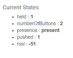
Reported number of buttons is 2 (Should be 1, I never sent "button2 *" message to HE.
Voltage Device status is not reported at all.
For some reason Temperature and Humidity child devices are created.
On the Arduino side I did not define these sensors.
In RM there is no Voltage Device present but I can check values through custom attributes.
This works but a bit inconvenient.
Here is my very simple Test Rule.
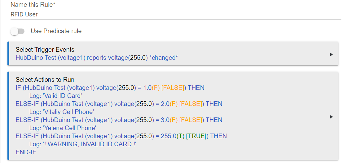
My question is:
Is the described above behavior normal or I am doing something wrong?
Correct. All data transfer between the HubDuino Parent Ethernet device and the microcontroller is via very simple "name value" space delimited pairs.
These are most likely simply results of your earlier attempts at running the ST_Anything_Multiples example sketch. Once you switched to using the ST_Anything_Buttons sketch, you would need to delete the unnecessary child devices.
Getting the numbers of buttons back down to one is not quite as simple. It might be easier to simply remove the Parent device, which will also remove all of the child devices, and then simply add it back as a new Parent Device. This will then cause a Refresh command to be sent to the microcontroller, which will reestablish everything cleanly on the Hubitat side of things.
Yep, that's a Rule Machine limitation, not an issue with HubDuino.
Looks pretty normal to me!
Yes, this did clean up all inconsistency with reporting number of buttons and child devices.
My test rules were destroyed but this was expected.
I got exactly what I wanted.
HubDuino processed RFID Card Reader and sends all info to the HE.
HubDuino holds small DB of the valid card IDs.
Blue LED is blinking (heart beat) indicating ESP8266 MC is running loop and alive.
When a Valid Card is detected it blinks once Green LED and sends User ID
(ha, ha, as a Voltage Level) to the HE. So HE knows exactly which Valid Card was used.
When Invalid Card is detected Red LED blinks and HE knows it was a failing
card read attempt.
As of now this project is not final final but (I guess) it is in a very good shape.
If somebody interested in this project I can share my HubDuino/Arduino app
but I have no idea how to do this (I am EE, not a SW developer).
Thank you again for the very valuable help with my little project,
- Vitaliy
3 Likes
Can you share the sketch?
Sure, here is a sketch:
// Enable Users Local Database
//#define CHECK_USER

#include <TerminalControl.h>

// SmartThings Library for ESP8266WiFi
#include <SmartThingsESP8266WiFi.h>

// ST_Anything Library
#include <Constants.h>       //Constants.h is designed to be modified by the end user to adjust behavior of the ST_Anything library
#include <Device.h>          //Generic Device Class, inherited by Sensor and Executor classes
#include <Sensor.h>          //Generic Sensor Class, typically provides data to ST Cloud (e.g. Temperature, Motion, etc...)
#include <Executor.h>        //Generic Executor Class, typically receives data from ST Cloud (e.g. Switch)
#include <InterruptSensor.h> //Generic Interrupt "Sensor" Class, waits for change of state on digital input
#include <PollingSensor.h>   //Generic Polling "Sensor" Class, polls Arduino pins periodically
#include <IS_Button.h>       //Implements an Interrupt Sensor (IS) to monitor the status of a digital input pin for button presses

#include <Everything.h>      //Master Brain of ST_Anything library that ties everything together and performs ST Shield communications

//******************************************************************************************
//
//ESP8266 WiFi Information
//
//******************************************************************************************
String str_ssid     = "";                             //  <---You must edit this line!
String str_password = "";                    //  <---You must edit this line!
IPAddress ip();       //Device IP Address       //  <---You must edit this line!
IPAddress gateway();   //Router gateway          //  <---You must edit this line!
IPAddress subnet(255, 255, 255, 0);   //LAN subnet mask         //  <---You must edit this line!
IPAddress dnsserver(); //DNS server              //  <---You must edit this line!
const unsigned int serverPort = 8090; // port to run the http server on

// Hubitat Hub Information
IPAddress hubIp();    // Hubitat hub ip         //  <---You must edit this line!
const unsigned int hubPort = 39501;   // Hubitat hub port

//******************************************************************************************
//
//  st::Everything::callOnMsgSend() optional callback routine.
//
//  This is a sniffer to monitor data being sent to ST.
//  This allows a user to act on data changes locally within the Arduino sktech.
//
//******************************************************************************************

void callback(const String &msg)
{
//  Serial.print(F("ST_Anything Callback: Sniffed data = "));
//  Serial.println(msg);

  //TODO:  Add local logic here to take action when a device's value/state is changed

  //Masquerade as the ThingShield to send data to the Arduino, as if from the ST Cloud (uncomment and edit following line)
  //st::receiveSmartString("Put your command here!");  //use same strings that the Device Handler would send
}

//-------------------------------------------------------------------------------

#ifdef CHECK_USER
//
// Valid ID Cards Parameters
//

// Number of Valid UIDs
const int N_Valid_IDs = 3;

// Valid RFID UIDs Array
int RFID_OK[N_Valid_IDs][2] =
{
// Facility ID, Card ID
   {0x00,       0x0000},
   {0x00,       0x0000},
   {0x00,       0x0000}
};

// User ID
byte userID = 0;
#endif

// ESP8266 Pins Definition

// RGB LED Control Pins
//#define LED_R_PIN  D0
//#define LED_G_PIN  D8
//#define LED_B_PIN  D2

// Data Input Interrupt Pins
#define Data_In_0_Pin D5
#define Data_In_1_Pin D6

// Heart Beat LED Divider dowto 1S
#define HB_LED_DIVIDER 100

// Max Number of Bits
#define MAX_BITS 100

// Time in mS to wait for another Weigand Pulse
#define WEIGAND_WAIT_TIME 5

// Parity Seeds
#define P_EVEN 0
#define P_ODD  1

// Parity Masks
#define PARITY_MASK_26B 0x1

// Stores all of the Data Bits
unsigned char dataBits[MAX_BITS];

// Number of currently captured bits
unsigned char bitCount;

// Wiegand Data Ready flag
bool flagWeigandDataReady;

// Countdown until we assume there are no more bits
unsigned int Weigand_Timeout_Counter = 1;

// Decoded Facility Code
unsigned long facilityCode = 0;

// Decoded Card Code
unsigned long cardCode = 0;

// Calculated Parity Bits
int parityEvenCode_26Bit = 0;
int parityOddCode_26Bit  = 0;

// For integration with Hubitat
String str_CardID;
String msg_Hubitat;

// 10mS Timer-1 Interrupt Flag
bool Flag_Timer1_10mS = false;

// Timer-1 Divider
// Sets Timer-1 Interval to 10mS
int Divider_Timer1 = 50000;

// Heart Beat LED Divider Counter
unsigned char HB_LED_DivCntr = 0;

//
// Subroutines
//

//=======================================================================
//                 Turn Off all LEDs Routine
//=======================================================================

void Turn_Off_All_LEDs()
{
//  digitalWrite(LED_R_PIN,   LOW);
//  digitalWrite(LED_G_PIN,   LOW);
//  digitalWrite(LED_B_PIN,   LOW);

  digitalWrite(LED_BUILTIN, HIGH);
}

//=======================================================================
//                 ESP8266 Timer-1 ISR
//=======================================================================

void ICACHE_RAM_ATTR Timer1_ISR()
{
  Flag_Timer1_10mS = true;
}

//=======================================================================
//                 ESP8266 Data-0 ISR
//=======================================================================

void ICACHE_RAM_ATTR Data_0_ISR()
{
  // Increment Bit Counter
  bitCount++;

  // Reset Data Ready flag
  flagWeigandDataReady = false;

  // Reset Weigand Timeout Counter
  Weigand_Timeout_Counter = 1;
}

//=======================================================================
//                 ESP8266 Data-1 ISR
//=======================================================================

void ICACHE_RAM_ATTR Data_1_ISR()
{
  // Store "1" in Data Buffer
  dataBits[bitCount] = 1;

  // Increment Bit Counter
  bitCount++;

  // Reset Data Ready flag
  flagWeigandDataReady = false;

  // Reset Weigand Timeout Counter
  Weigand_Timeout_Counter = 1;
}

//=======================================================================
//                 Setup
//=======================================================================

void setup()
{
  // LED Control Pins
//  pinMode(LED_R_PIN,   OUTPUT);
//  pinMode(LED_G_PIN,   OUTPUT);
//  pinMode(LED_B_PIN,   OUTPUT);
  pinMode(LED_BUILTIN, OUTPUT);

  // Data Input Interrupt Pins
  pinMode(Data_In_0_Pin, INPUT_PULLUP);
  pinMode(Data_In_1_Pin, INPUT_PULLUP);

  // Turn Off all LEDs
  Turn_Off_All_LEDs();

  // Initialize Timer-1
  /* Dividers:
    TIM_DIV1   = 0 //80MHz (80 ticks/us - 104857.588 us max)
    TIM_DIV16  = 1 //5MHz  (5  ticks/us - 1677721.4 us max)
    TIM_DIV256 = 3 //312.5Khz (1 tick = 3.2us - 26843542.4 us max)
    Reloads:
    TIM_SINGLE   0 //on interrupt routine you need to write a new value to start the timer again
    TIM_LOOP     1 //on interrupt the counter will start with the same value again
  */
  timer1_enable(TIM_DIV16, TIM_EDGE, TIM_LOOP);

  // for fclk=80MHz  (fclck/prescale*t)-1  Register 32bit?
  timer1_write(Divider_Timer1 - 1);

  // Heart Beat LED Divider Counter
  HB_LED_DivCntr = 1;

  // Reset 10mS Timer-1Interrupt Flag
  Flag_Timer1_10mS = false;

  // Set Data Ready flag
  flagWeigandDataReady = true;

  // Initialize Weigand Timeout Counter
  Weigand_Timeout_Counter = 1;

  // Cleanup and get ready for the Next Card
  CleanUp();

  // Initialize Timer-1 ISR
  timer1_attachInterrupt(Timer1_ISR);

  // Initialize Data In Interrupts
  //Data-0 Input Interrupt
  attachInterrupt(digitalPinToInterrupt(Data_In_0_Pin), Data_0_ISR, FALLING);

  //Data-1 Input Interrupt
  attachInterrupt(digitalPinToInterrupt(Data_In_1_Pin), Data_1_ISR, FALLING);

  // Initialize RS232 Port for PC Communication
  Serial.begin(115200);

  //
  // HubDuino Executors
  //

  //*****************************************************************************
  //
  //  Configure debug print output from each main class
  //  -Note: Set these to "false" if using Hardware Serial on pins 0 & 1
  //         to prevent communication conflicts with the ST Shield communications
  //
  //*****************************************************************************
  st::Everything::debug      = false;

  st::Executor::debug        = false;
  st::Device::debug          = false;
  st::PollingSensor::debug   = false;
  st::InterruptSensor::debug = false;

  //*****************************************************************************
  //Initialize the "Everything" Class
  //*****************************************************************************

  //Initialize the optional local callback routine (safe to comment out if not desired)
  st::Everything::callOnMsgSend = callback;

  //Create the SmartThings ESP8266WiFi Communications Object
  //STATIC IP Assignment - Recommended
  st::Everything::SmartThing = new st::SmartThingsESP8266WiFi(str_ssid, str_password, ip, gateway, subnet, dnsserver, serverPort, hubIp, hubPort, st::receiveSmartString, "OfficeESP");

  //Run the Everything class' init() routine which establishes WiFi communications with SmartThings Hub
  st::Everything::init();

  //*****************************************************************************
  //Initialize each of the devices which were added to the Everything Class
  //*****************************************************************************
  st::Everything::initDevices();

  delay(2000);

  // Clear Terminal Screen
  Serial.print(ClearScreen);
  Serial.println();

  Serial.print(CharCyan);
  Serial.print("HID RFID Card Reader is Ready");
  Serial.println();
  Serial.println();
}

//=======================================================================
//                 Main Loop
//=======================================================================

void loop()
{
  //
  // 10mS Timer-1 Interrupt
  //

  if (true == Flag_Timer1_10mS)
  {
    // Reset Timer-1 Interrupt Flag
    Flag_Timer1_10mS = false;

    // Blink Heart Beat LED with 1Sec Pulse/Pause
    if (HB_LED_DivCntr < HB_LED_DIVIDER)
    {
      HB_LED_DivCntr++;
    }
    else
    {
      HB_LED_DivCntr = 1;
      digitalWrite(LED_BUILTIN, !(digitalRead(LED_BUILTIN)));
    }

    //
    // HID Reader Support
    //

    // Wait for the Wiengand Timeout to make sure there are
    // no more Data Pulses before processing Data Buffer
    if  ((Weigand_Timeout_Counter < WEIGAND_WAIT_TIME)
      && (false == flagWeigandDataReady))
    {
      Weigand_Timeout_Counter++;
    }
    else if (bitCount > 0)
    {
      flagWeigandDataReady = true;

      // Process RFID Weigand HID Card Reader Data
      Weigand_HID_Card_Reader();
    }
  }

  //*****************************************************************************
  //
  //  HubDuiono
  //
  //  Execute the Everything run method which takes care of "Everything"
  //
  //*****************************************************************************
  st::Everything::run();
}

//=======================================================================
//                 Print Result
//=======================================================================

void printResult()
{
  Serial.print(CharYellow);
  Serial.print("Facility Code    :  ");
  Serial.print(CharCyan);
  Serial.print("0x");
  if (0 == (facilityCode >> 4))
  {
    Serial.print("0");
  }
  Serial.print(facilityCode, HEX);

  Serial.print(CharWhite);
  Serial.print("      ");
  Serial.print(facilityCode);
  Serial.println();

  Serial.print(CharYellow);
  Serial.print("Card Code        :  ");
  Serial.print(CharCyan);
  Serial.print("0x");
  if (0 == (cardCode >> 12))
  {
    Serial.print("0");
  }
  Serial.print(cardCode, HEX);

  Serial.print(CharWhite);
  Serial.print("    ");
  Serial.print(cardCode);
  Serial.println();

#ifdef CHECK_USER
  Serial.print(CharYellow);
  Serial.print("User ID          :  ");
  Serial.print(CharCyan);
  if (0 == userID)
  {
    Serial.print("Invalid User ID");
  }
  else
  {
    Serial.print(userID);
  }
  Serial.println();
#endif

  Serial.println();
}

//=======================================================================
//                 Check Parity
//=======================================================================

unsigned char checkParity(unsigned X, char P, int Mask)
{
  int Parity = P;

  while(X != 0)
  {
    Parity ^= X;
    X >>= 1;
  }

  return (Parity & Mask);
}

//=======================================================================
//                 Check Parity Bits for the 26-Bit Card Format
//=======================================================================

void checkParity_26Bit(int parityEvenCode, int parityOddCode)
{
  unsigned char parityEvenBit = 0;
  unsigned char parityOddBit  = 0;

  // Check Parity Bits
  parityEvenBit = checkParity(parityEvenCode, P_EVEN, PARITY_MASK_26B);
  parityOddBit  = checkParity(parityOddCode,  P_ODD,  PARITY_MASK_26B);

  Serial.print(CharYellow);
  Serial.print("Even Parity Bit  :  ");
  Serial.print(CharCyan);
  Serial.print(parityEvenBit);
  Serial.println();

  Serial.print(CharYellow);
  Serial.print("Odd  Parity Bit  :  ");
  Serial.print(CharCyan);
  Serial.print(parityOddBit);
  Serial.println();
  Serial.println();

  if  ((dataBits[0]  != parityEvenBit)
    || (dataBits[25] != parityOddBit ))
  {
    Serial.print(CharYellow);
    Serial.print("Warning! Corrupted Parity Bits");
    Serial.println();
    Serial.println();
  }
}

//=======================================================================
//                 Cleanup all Variables and Buffers
//=======================================================================

void CleanUp()
{
  bitCount             = 0;
  facilityCode         = 0;
  cardCode             = 0;
#ifdef CHECK_USER
  userID               = 0;
#endif
  parityEvenCode_26Bit = 0;
  parityOddCode_26Bit  = 0;

  unsigned char I;
  for (I = 0; I < MAX_BITS; I++)
  {
    dataBits[I] = 0;
  }
}

//=======================================================================
//                 Print Data Buffer
//=======================================================================

void printDataBuf(unsigned char bufferSize)
{
  unsigned char I;
  for (I = 0; I < bufferSize; I++)
  {
    if (0 == dataBits[I])
    {
      Serial.print("0");
    }
    else
    {
      Serial.print("1");
    }

    // Separate Parity Bits by Space
    if ((I == 0) || (I == (bufferSize - 2)))
    {
      Serial.print(" ");
    }
  }
}

//=======================================================================
//                 Compare Current Card ID
//                 with predefined Valid Card IDs
//=======================================================================

#ifdef CHECK_USER
byte Compare_IDs(byte N_Valid_IDs)
{
  // User ID associated with RFID Card
  byte User_ID = 0;

  for (byte I = 0; I < N_Valid_IDs; I++)
  {
    if  ((facilityCode == RFID_OK[I][0])
      && (cardCode     == RFID_OK[I][1]))
    {
      User_ID = (I + 1);
      return User_ID;
    }
  }

  return User_ID;
}
#endif

//=======================================================================
//                 Message for Integration with Hubitat
//=======================================================================

void msgHubitat()
{
  // Construct message for integration with Hubitat
  str_CardID  = String(((facilityCode << 16) | cardCode), DEC);
  msg_Hubitat = "voltage1 " + str_CardID;

  // Send Card ID message to Hubitat
  st::Everything::sendSmartString(msg_Hubitat);

  Serial.print(CharWhite);
  Serial.print("HubDuino Message :  ");
  Serial.print(CharCyan);
  Serial.print(msg_Hubitat);
  Serial.println();
  Serial.println();

  // Send Trigger Event to Hubitat
  msg_Hubitat = "button1 pushed";
  st::Everything::sendSmartString(msg_Hubitat);
}

//=======================================================================
//                 Weigand HID Card Reader Data Processing
//=======================================================================

void Weigand_HID_Card_Reader()
{
  unsigned char I;

  // Print Data Buffer size
  Serial.print(CharWhite);
  Serial.print(bitCount);
  Serial.print(" Data Bits Acquired");
  Serial.println();

  // Print raw Data Buffer content
  Serial.print(CharGreen);
  printDataBuf(bitCount);
  Serial.println();
  Serial.println();

  // Standard 26 Bit Card Format
  if (bitCount == 26)
  {
    Serial.print(CharWhite);
    Serial.print("Standard 26-bit Card");
    Serial.println();

    Serial.println();

    // Facility Code Bits 1 to 8
    for (I = 1; I < 9; I++)
    {
      facilityCode <<= 1;
      facilityCode |= dataBits[I];
    }

    // Card Code Bits 9 to 25
    for (I = 9; I < 25; I++)
    {
      cardCode <<= 1;
      cardCode |= dataBits[I];
    }

    // Even Parity Bits 1 to 12
    for (I = 1; I < 13; I++)
    {
      parityEvenCode_26Bit <<= 1;
      parityEvenCode_26Bit |= dataBits[I];
    }

    // Even Parity Bits 1 to 12
    for (I = 13; I < 25; I++)
    {
      parityOddCode_26Bit <<= 1;
      parityOddCode_26Bit |= dataBits[I];
    }

    // Check Parity Bits
    checkParity_26Bit(parityEvenCode_26Bit, parityOddCode_26Bit);
  }
  else
  {
    Serial.println();
    Serial.print("Unable to decode ID Card");
    Serial.println();

    // Cleanup and get ready for the Next Card
    CleanUp();

    return;
  }

  // Find a Valid Card ID
#ifdef CHECK_USER
  userID = Compare_IDs(N_Valid_IDs);
#endif

  // Print Result
  printResult();

  // Message for Integration with Hubitat
  msgHubitat();

  // Cleanup and get ready for the Next Card
  CleanUp();
}

//=======================================================================
Frankly, I am not using this project anymore because I switch to 100% hands free project.
This touchless one involves: Home Assistant + ESPresense + BLE Beacons
My knowledge of electronics and programming is very limited, this rfid project is already borderline.
If you don't mind I have more questions: I have a D1 mini board and a PN532 instead of RC522. Will it work the same? Is the wiring the same?
As I already mentioned, I am not using these RF projects since I switched to BLE Beacons instead of RF ID cards. But I did experimented with different RF ID readers and got them working. The sketch on my previous message was a final Hubduino project but was using HID RF reader (125KHz) with WEIGAND interface. PN532 and RC522 RF Readers are for the 13.56MHz RF ID cards. I have a tested and debugged Arduino Sketches for both these chips but never integrated them with Hubduino (please check sketches below.
D1 Mini seems to be a ESP8266 based. It should work but may need different IO pins assignment.
Here is a sketch for the PN532 RF Reader (only Arduino, no integration with Hubduino):
//*******************************************************************************
//  File: RFID_MFRC522.ino
//
//  Summary:  This Arduino Sketch is a Control Software for the
//            MFRC522 Card Reader connected to the
//            ESP8266 NodeMCU Microcontroller
//
//  Change History:
//
//    Date        Who                   What
//    ----        ---                   ----
//    11-10-2021  Vitaliy Kholyavenko   Original Creation
//
//*******************************************************************************

//-------------------------------------------------------------------------------

// Include Libraries for the PN532 RDID Chip
#include <SPI.h>
#include <Adafruit_PN532.h>

// SPI Interface is used for the communication
// between boards
#include <SPI.h>

// ESP8266 Pins Definition
// RGB LED Control Pins
#define LED_R_PIN  D0
#define LED_G_PIN  D3
#define LED_B_PIN  D8

// On Board LED Pin
#define LED_B_ONBRD_PIN  D4

// Define SPI Control pins for the PN532 Chip
#define PN532_RESET D1
#define PN532_SS    D2

// Number of Status LED Blinks
#define N_LED_BLINKS 5

//
// Valid ID Cards Parameters
//

// Number of Valid UIDs
const int N_Valid_IDs = 6;

// Valid RFID UIDs Array
byte RFID_OK[N_Valid_IDs][7] =
{
  {0x81, 0x99, 0x83, 0x20, 0x00, 0x00, 0x00}, // 4 byte UID
  {0x04, 0x10, 0x2E, 0x01, 0x2A, 0x48, 0x03}, // 7 byte UID
  {0x04, 0x00, 0xB4, 0x01, 0xF5, 0x48, 0x03}, // 7 byte UID
  {0x04, 0x10, 0x1E, 0x4B, 0xE2, 0x4F, 0x80}, // 7 byte UID
  {0x04, 0x48, 0x24, 0xCB, 0x8D, 0x4A, 0x80}, // 7 byte UID
  {0xD6, 0xE9, 0xB5, 0x01, 0x00, 0x00, 0x00}  // 4 byte UID
};

//-------------------------------------------------------------------------------

// LED On/Off Control levels
#define Active_Low   LOW
#define Active_High  HIGH

//
// Define Status LEDs Blinking Parameters
//
// ON/OFF Timing Parameter Value is in mS
//
// Parameter "*_N_BLINKS" Control Value:
//  N - Defined Number of LED Blinks
//  0 - LED Blinking is OFF
// -1 - Infinite LED Blinking
//

// Red Status LED
#define LED_R_ON_TIME   100
#define LED_R_OFF_TIME  100
#define LED_R_N_BLINKS  0

// Green Status LED
#define LED_G_ON_TIME   100
#define LED_G_OFF_TIME  100
#define LED_G_N_BLINKS  0

// Blue Status LED
#define LED_B_ON_TIME   100
#define LED_B_OFF_TIME  900
#define LED_B_N_BLINKS  0

// On-Board Blue Status LED
#define LED_B_ONBRD_ON_TIME   500
#define LED_B_ONBRD_OFF_TIME  500
#define LED_B_ONBRD_N_BLINKS  -1

// Status LED Structure
typedef struct
{
  byte           LED_Pin;
  unsigned long  LED_Time_On;
  unsigned long  LED_Time_Off;
  int            LED_N_Blinks;
  byte           LED_On;
  unsigned long  LED_Millis = 0;
} StatusLED;

// Generally, you should use "unsigned long" for variables that hold time
// The value will quickly become too large for an int to store
unsigned long currentMillis = 0;

// Instansiate Status LEDs Array
StatusLED LED_R;
StatusLED LED_G;
StatusLED LED_B;
StatusLED LED_B_ONBRD;

// Create HW SPI PN532 Instance
Adafruit_PN532 nfc(PN532_SS);

//-------------------------------------------------------------------------------

//*******************************************************************************
//Arduino Setup() routine
//*******************************************************************************

void setup()
{

#if 1
  // Set LED Control Pins as Output:
  pinMode(LED_R_PIN,       OUTPUT);
  pinMode(LED_G_PIN,       OUTPUT);
  pinMode(LED_B_PIN,       OUTPUT);
  //pinMode(LED_B_ONBRD_PIN, OUTPUT);

  // Turn Off all LEDs
  Turn_Off_All_LEDs();

  // Define Parameters for all Status LEDs
  LED_R = {LED_R_PIN, LED_R_ON_TIME, LED_R_OFF_TIME, LED_R_N_BLINKS, Active_High};
  LED_G = {LED_G_PIN, LED_G_ON_TIME, LED_G_OFF_TIME, LED_G_N_BLINKS, Active_High};
  LED_B = {LED_B_PIN, LED_B_ON_TIME, LED_B_OFF_TIME, LED_B_N_BLINKS, Active_High};

  LED_B_ONBRD = {LED_B_ONBRD_PIN, LED_B_ONBRD_ON_TIME, LED_B_ONBRD_OFF_TIME, LED_B_ONBRD_N_BLINKS, Active_Low};
#endif

  // Initialize serial communications with the PC
  Serial.begin(115200);

  Serial.println();
  Serial.println();

  // Init SPI bus
  SPI.begin();

  // Init PN532
  nfc.begin();

  uint32_t versiondata = nfc.getFirmwareVersion();
  if (! versiondata) {
    Serial.print("Didn't find PN53x board");
    while (1); // halt
  }

  // Got OK data, print it out!
  Serial.print("Found chip PN5"); Serial.println((versiondata>>24) & 0xFF, HEX);
  Serial.print("Firmware ver. "); Serial.print((versiondata>>16) & 0xFF, DEC);
  Serial.print('.'); Serial.println((versiondata>>8) & 0xFF, DEC);

  // Set the max number of retry attempts to read from a card
  // This prevents us from waiting forever for a card, which is
  // the default behaviour of the PN532.
  nfc.setPassiveActivationRetries(0xFF);

  // configure board to read RFID tags
  nfc.SAMConfig();

  Serial.println("Waiting for an ISO14443A card...");

  Serial.println();
  Serial.println();
}

//-------------------------------------------------------------------------------

//*******************************************************************************
//Arduino Loop() routine
//*******************************************************************************

void loop()
{
#if 1
  // Update Current Millis Value
  // (used for Status LEDs control)
  currentMillis = millis();

  // Blink Satus LEDs
  Blink_LED(&LED_R);
  Blink_LED(&LED_G);
  Blink_LED(&LED_B);

  // Heart Beat LED
  //Blink_LED(&LED_B_ONBRD);

  // Read Card ID
  if ((LED_B.LED_N_Blinks) == -1)
  {
    Read_Card_ID();
  }

  // Start LED_B Infinite Blinking
  if  (((LED_R.LED_N_Blinks) == 0)
    && ((LED_G.LED_N_Blinks) == 0)
    && ((LED_B.LED_N_Blinks) == 0))
  {
    (LED_B.LED_N_Blinks) = -1;
  }
#endif

//  Read_Card_ID();

}

//-------------------------------------------------------------------------------

// Blink LED Routine
void Blink_LED(StatusLED *LED)
{
  // Do nothing if Requested Number of LED Blinks is 0
  if ((LED -> LED_N_Blinks) == 0)
  {
    return;
  }

  // Read current LED State
  byte LED_State = digitalRead(LED -> LED_Pin);

  // Invert LED State if LED Control is Active Low
  if ((LED -> LED_On) == LOW)
  {
    LED_State = (LED_State ^ 0x1);
  }

  // Check On/Off LED Timing
  if  (((LED_State == LOW)  && ((currentMillis - (LED -> LED_Millis)) > (LED -> LED_Time_Off)))
    || ((LED_State == HIGH) && ((currentMillis - (LED -> LED_Millis)) > (LED -> LED_Time_On ))))
  {
    // Update Millis Variable for the selected LED
    (LED -> LED_Millis) = currentMillis;

    // Check and Update Number of Blinks variable
    if (((LED -> LED_N_Blinks) > 0)
      && (LED_State == HIGH))
    {
      (LED -> LED_N_Blinks)--;
    }

    // Modify LED Control Pin
    digitalWrite((LED -> LED_Pin), !digitalRead(LED -> LED_Pin));
  }
}

//-------------------------------------------------------------------------------

// Turn Off all LEDs Routine
void Turn_Off_All_LEDs()
{
  digitalWrite(LED_R_PIN, LOW);
  digitalWrite(LED_G_PIN, LOW);
  digitalWrite(LED_B_PIN, LOW);

  digitalWrite(LED_B_ONBRD_PIN, HIGH);
}

//-------------------------------------------------------------------------------

// Dump a Byte Array as HEX values to the PC Serial Port
void dump_byte_array(byte *buffer, byte bufferSize)
{
  for (byte i = 0; i < bufferSize; i++)
  {
    Serial.print(buffer[i] < 0x10 ? " 0" : " ");
    Serial.print(buffer[i], HEX);
  }
}

//-------------------------------------------------------------------------------

// Compare Current Card ID with predefined Valid Card IDs.
byte compare_byte_array(byte *buffer, byte bufferSize)
{
  // User ID associated with RFID Card
  byte User_ID = 0;

  for (byte n = 0; n < N_Valid_IDs; n++)
  {
    for (byte i = 0; i < bufferSize; i++)
    {
      if (buffer[i] != RFID_OK[n][i])
      {
        break;
      }
      else if (i == (bufferSize - 1))
      {
        User_ID = (n + 1);
        return User_ID;
      }
    }
  }
  return User_ID;
}

//-------------------------------------------------------------------------------

#if 0
// Read Card ID with MFRC522 Chip
void Read_Card_ID()
{
  // Reset the loop if no new card present on the sensor/reader.
  // This saves the entire process when idle.
  if ( ! mfrc522.PICC_IsNewCardPresent())
  {
    return;
  }

  // Select one of the valid cards
  if ( ! mfrc522.PICC_ReadCardSerial())
  {
    return;
  }

  // Stop LED_B Infinite Blinking
  // and turn it Off
  (LED_B.LED_N_Blinks) = 0;
  digitalWrite(LED_B_PIN, LOW);

  // Print Card UID
  Serial.print(F("Card UID is  : "));
  dump_byte_array(mfrc522.uid.uidByte, mfrc522.uid.size);
  Serial.println();

  // Print PICC Type
  Serial.print(F("PICC Type is :  "));
  MFRC522::PICC_Type piccType = mfrc522.PICC_GetType(mfrc522.uid.sak);
  Serial.println(mfrc522.PICC_GetTypeName(piccType));

  // Halt PICC
  mfrc522.PICC_HaltA();

  // Stop encryption on PCD
  mfrc522.PCD_StopCrypto1();

  // Compare Card UID with Valid ID
  byte User_ID = compare_byte_array(mfrc522.uid.uidByte, mfrc522.uid.size);

  // Print User ID and Blink an appropriate LED
  if (0 == User_ID)
  {
    Serial.print(F("Invalid Card UID"));
    (LED_R.LED_N_Blinks) = N_LED_BLINKS;
  }
  else
  {
    Serial.print(F("User ID is   :  "));
    Serial.print(User_ID, DEC);
    (LED_G.LED_N_Blinks) = N_LED_BLINKS;
  }
  Serial.println();
  Serial.println();
}
#endif

//-------------------------------------------------------------------------------

// Read Card ID with PN532 Chip
void Read_Card_ID()
{
  boolean success;

  // Buffer to store the returned UID
  uint8_t uid[] = { 0, 0, 0, 0, 0, 0, 0 };

  // Length of the UID (4 or 7 bytes depending on ISO14443A card type)
  uint8_t uidLength;

  // Wait for an ISO14443A type cards (Mifare, etc.).  When one is found
  // 'uid' will be populated with the UID, and uidLength will indicate
  // if the uid is 4 bytes (Mifare Classic) or 7 bytes (Mifare Ultralight)
  success = nfc.readPassiveTargetID(PN532_MIFARE_ISO14443A, &uid[0], &uidLength);

  if (success)
  {
    Serial.println("Found a card!");
    Serial.print("UID Length: ");
    Serial.print(uidLength, DEC);
    Serial.println(" bytes");
    Serial.print("UID Value: ");

    for (uint8_t i=0; i < uidLength; i++)
    {
      Serial.print(" 0x");
      Serial.print(uid[i], HEX);
    }

    Serial.println();

    // Wait 1 second before continuing
    delay(1000);
  }
  else
  {
    // PN532 probably timed out waiting for a card
    Serial.println("Timed out waiting for a card");
  }
}

//-------------------------------------------------------------------------------
And here is a sketch for the MFRC522 RF Reader (only Arduino, no integration with Hubduino):
//*******************************************************************************
//  File: RFID_MFRC522.ino
//
//  Summary:  This Arduino Sketch is a Control Software for the
//            MFRC522 Card Reader connected to the
//            ESP8266 NodeMCU Microcontroller
//
//  Change History:
//
//    Date        Who                   What
//    ----        ---                   ----
//    11-10-2021  Vitaliy Kholyavenko   Original Creation
//
//*******************************************************************************

//-------------------------------------------------------------------------------

// Include Libraries for the MFRC522 RDID Chip
#include <deprecated.h>
#include <MFRC522.h>
#include <MFRC522Extended.h>
#include <require_cpp11.h>

// SPI Interface is used for the communication
// between boards
#include <SPI.h>

// ESP8266 Pins Definition
// RGB LED Control Pins
#define LED_R_PIN  D0
#define LED_G_PIN  D3
#define LED_B_PIN  D8

// On Board LED Pin
#define LED_B_ONBRD_PIN  D4

#define RST_PIN    D1
#define SS_PIN     D2

// Number of Status LED Blinks
#define N_LED_BLINKS 5

//
// Valid ID Cards Parameters
//

// Number of Valid UIDs
const int N_Valid_IDs = 6;

// Valid RFID UIDs Array
byte RFID_OK[N_Valid_IDs][7] =
{
  {0x81, 0x99, 0x83, 0x20, 0x00, 0x00, 0x00}, // 4 byte UID
  {0x04, 0x10, 0x2E, 0x01, 0x2A, 0x48, 0x03}, // 7 byte UID
  {0x04, 0x00, 0xB4, 0x01, 0xF5, 0x48, 0x03}, // 7 byte UID
  {0x04, 0x10, 0x1E, 0x4B, 0xE2, 0x4F, 0x80}, // 7 byte UID
  {0x04, 0x48, 0x24, 0xCB, 0x8D, 0x4A, 0x80}, // 7 byte UID
  {0xD6, 0xE9, 0xB5, 0x01, 0x00, 0x00, 0x00}  // 4 byte UID
};

//-------------------------------------------------------------------------------

// LED On/Off Control levels
#define Active_Low   LOW
#define Active_High  HIGH

//
// Define Status LEDs Blinking Parameters
//
// ON/OFF Timing Parameter Value is in mS
//
// Parameter "*_N_BLINKS" Control Value:
//  N - Defined Number of LED Blinks
//  0 - LED Blinking is OFF
// -1 - Infinite LED Blinking
//

// Red Status LED
#define LED_R_ON_TIME   100
#define LED_R_OFF_TIME  100
#define LED_R_N_BLINKS  0

// Green Status LED
#define LED_G_ON_TIME   100
#define LED_G_OFF_TIME  100
#define LED_G_N_BLINKS  0

// Blue Status LED
#define LED_B_ON_TIME   100
#define LED_B_OFF_TIME  900
#define LED_B_N_BLINKS  0

// On-Board Blue Status LED
#define LED_B_ONBRD_ON_TIME   500
#define LED_B_ONBRD_OFF_TIME  500
#define LED_B_ONBRD_N_BLINKS  -1

// Status LED Structure
typedef struct
{
  byte           LED_Pin;
  unsigned long  LED_Time_On;
  unsigned long  LED_Time_Off;
  int            LED_N_Blinks;
  byte           LED_On;
  unsigned long  LED_Millis = 0;
} StatusLED;

// Generally, you should use "unsigned long" for variables that hold time
// The value will quickly become too large for an int to store
unsigned long currentMillis = 0;

// Instansiate Status LEDs Array
StatusLED LED_R;
StatusLED LED_G;
StatusLED LED_B;
StatusLED LED_B_ONBRD;

// Create MFRC522 instance
MFRC522 mfrc522(SS_PIN, RST_PIN);

//-------------------------------------------------------------------------------

//*******************************************************************************
//Arduino Setup() routine
//*******************************************************************************

void setup()
{
  // Set LED Control Pins as Output:
  pinMode(LED_R_PIN,       OUTPUT);
  pinMode(LED_G_PIN,       OUTPUT);
  pinMode(LED_B_PIN,       OUTPUT);
  pinMode(LED_B_ONBRD_PIN, OUTPUT);

  // Turn Off all LEDs
  Turn_Off_All_LEDs();

  // Define Parameters for all Status LEDs
  LED_R = {LED_R_PIN, LED_R_ON_TIME, LED_R_OFF_TIME, LED_R_N_BLINKS, Active_High};
  LED_G = {LED_G_PIN, LED_G_ON_TIME, LED_G_OFF_TIME, LED_G_N_BLINKS, Active_High};
  LED_B = {LED_B_PIN, LED_B_ON_TIME, LED_B_OFF_TIME, LED_B_N_BLINKS, Active_High};

  LED_B_ONBRD = {LED_B_ONBRD_PIN, LED_B_ONBRD_ON_TIME, LED_B_ONBRD_OFF_TIME, LED_B_ONBRD_N_BLINKS, Active_Low};

  // Initialize serial communications with the PC
  Serial.begin(115200);

  // Init SPI bus
  SPI.begin();

  // Init MFRC522
  mfrc522.PCD_Init();

  Serial.println();
  Serial.println();
}

//-------------------------------------------------------------------------------

//*******************************************************************************
//Arduino Loop() routine
//*******************************************************************************

void loop()
{
  // Update Current Millis Value
  // (used for Status LEDs control)
  currentMillis = millis();

  // Blink Satus LEDs
  Blink_LED(&LED_R);
  Blink_LED(&LED_G);
  Blink_LED(&LED_B);

  // Heart Beat LED
  Blink_LED(&LED_B_ONBRD);

  // Read Card ID
  if ((LED_B.LED_N_Blinks) == -1)
  {
    Read_Card_ID();
  }

  // Start LED_B Infinite Blinking
  if  (((LED_R.LED_N_Blinks) == 0)
    && ((LED_G.LED_N_Blinks) == 0)
    && ((LED_B.LED_N_Blinks) == 0))
  {
    (LED_B.LED_N_Blinks) = -1;
  }
}

//-------------------------------------------------------------------------------

// Blink LED Routine
void Blink_LED(StatusLED *LED)
{
  // Do nothing if Requested Number of LED Blinks is 0
  if ((LED -> LED_N_Blinks) == 0)
  {
    return;
  }

  // Read current LED State
  byte LED_State = digitalRead(LED -> LED_Pin);

  // Invert LED State if LED Control is Active Low
  if ((LED -> LED_On) == LOW)
  {
    LED_State = (LED_State ^ 0x1);
  }

  // Check On/Off LED Timing
  if  (((LED_State == LOW)  && ((currentMillis - (LED -> LED_Millis)) > (LED -> LED_Time_Off)))
    || ((LED_State == HIGH) && ((currentMillis - (LED -> LED_Millis)) > (LED -> LED_Time_On ))))
  {
    // Update Millis Variable for the selected LED
    (LED -> LED_Millis) = currentMillis;

    // Check and Update Number of Blinks variable
    if (((LED -> LED_N_Blinks) > 0)
      && (LED_State == HIGH))
    {
      (LED -> LED_N_Blinks)--;
    }

    // Modify LED Control Pin
    digitalWrite((LED -> LED_Pin), !digitalRead(LED -> LED_Pin));
  }
}

//-------------------------------------------------------------------------------

// Turn Off all LEDs Routine
void Turn_Off_All_LEDs()
{
  digitalWrite(LED_R_PIN, LOW);
  digitalWrite(LED_G_PIN, LOW);
  digitalWrite(LED_B_PIN, LOW);

  digitalWrite(LED_B_ONBRD_PIN, HIGH);
}

//-------------------------------------------------------------------------------

// Dump a Byte Array as HEX values to the PC Serial Port
void dump_byte_array(byte *buffer, byte bufferSize)
{
  for (byte i = 0; i < bufferSize; i++)
  {
    Serial.print(buffer[i] < 0x10 ? " 0" : " ");
    Serial.print(buffer[i], HEX);
  }
}

//-------------------------------------------------------------------------------

// Compare Current Card ID with predefined Valid Card IDs.
byte compare_byte_array(byte *buffer, byte bufferSize)
{
  // User ID associated with RFID Card
  byte User_ID = 0;

  for (byte n = 0; n < N_Valid_IDs; n++)
  {
    for (byte i = 0; i < bufferSize; i++)
    {
      if (buffer[i] != RFID_OK[n][i])
      {
        break;
      }
      else if (i == (bufferSize - 1))
      {
        User_ID = (n + 1);
        return User_ID;
      }
    }
  }
  return User_ID;
}

//-------------------------------------------------------------------------------

// Read Card ID
void Read_Card_ID()
{
  // Reset the loop if no new card present on the sensor/reader.
  // This saves the entire process when idle.
  if ( ! mfrc522.PICC_IsNewCardPresent())
  {
    return;
  }

  // Select one of the valid cards
  if ( ! mfrc522.PICC_ReadCardSerial())
  {
    return;
  }

  // Stop LED_B Infinite Blinking
  // and turn it Off
  (LED_B.LED_N_Blinks) = 0;
  digitalWrite(LED_B_PIN, LOW);

  // Print Card UID
  Serial.print(F("Card UID is  : "));
  dump_byte_array(mfrc522.uid.uidByte, mfrc522.uid.size);
  Serial.println();

  // Print PICC Type
  Serial.print(F("PICC Type is :  "));
  MFRC522::PICC_Type piccType = mfrc522.PICC_GetType(mfrc522.uid.sak);
  Serial.println(mfrc522.PICC_GetTypeName(piccType));

  // Halt PICC
  mfrc522.PICC_HaltA();

  // Stop encryption on PCD
  mfrc522.PCD_StopCrypto1();

  // Compare Card UID with Valid ID
  byte User_ID = compare_byte_array(mfrc522.uid.uidByte, mfrc522.uid.size);

  // Print User ID and Blink an appropriate LED
  if (0 == User_ID)
  {
    Serial.print(F("Invalid Card UID"));
    (LED_R.LED_N_Blinks) = N_LED_BLINKS;
  }
  else
  {
    Serial.print(F("User ID is   :  "));
    Serial.print(User_ID, DEC);
    (LED_G.LED_N_Blinks) = N_LED_BLINKS;
  }
  Serial.println();
  Serial.println();
}

//-------------------------------------------------------------------------------
I understand, you are looking for something "ready to go".
This will be a complete project for the HID RD ID reader (125Khz RF Tags).
For the PN532 and RC522 chips I have only ready to go Arduino sketches.
I am sorry, but I have no time and interest to integrate these sketches with Hubduino and what is more important, to debug an created project(s).
Apparently I underestimated the process by quite a bit. it's clearly out of my league.
Thank you anyway for the information.

