Hub: C8-Pro running 2.4.3.137
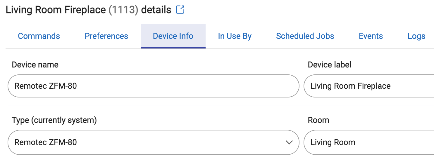
Device: Remotec ZFM-80US (Z-Wave)
Overview:
The gas fireplace is one of the last things in my house to get smart control via my Hubitat hub and integration with Apple HomeKit. I have been nervous to attempt as not to want to mess with anything dealing with natural gas in the house. However, after talking with the my fireplace technician that does maintenance on the insert, he assured me there are failsafes in place to prevent gas flow say when the smart switch is acticated and the pilot light is out.
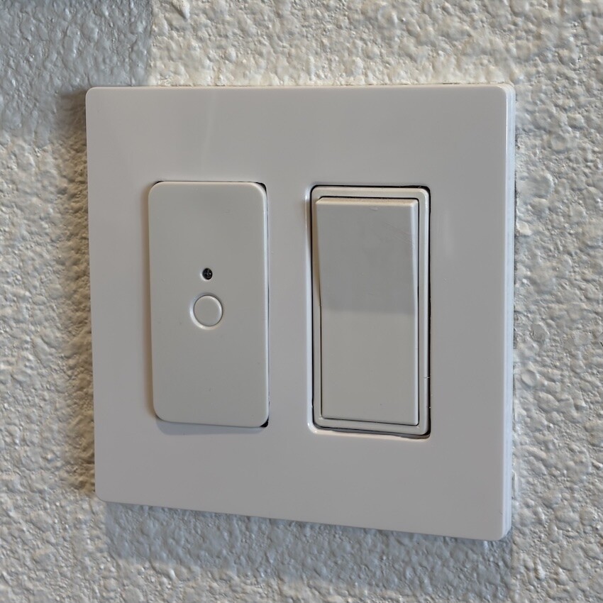
After doing some searches, many have used ZEN smart relays but these require install under the insert and need a 110V AC plug nearby to power the smart relay. I wanted to do everything at the wall where the simple switch was installed to control the millivolt operation. After doing some research with ChatGPT I found the following option which checked all my boxes. The smart switch acts as both a physical switch and smart remote all in on unit which was important. I did not want to get into a siutation where the physca switch and relay were out of sorts. It's powered by 110V in-wall AC that I used from a nearby powered switch in the same area.
Wiring Setup:
I followed the "Figure 2" wiring diagram from the manual, only difference was I omitted the external physical switch which was not needed. The physical button on the smart remote itself is perfect.
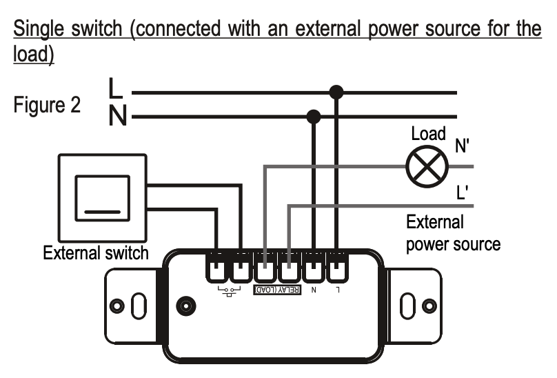
- Black (hot) → L
- White (neutral) → N
- Millivolt TH / TP → Relay Load / Relay Load (polarity doesn't matter)
Final Install:
Including the Remotec ZFM-80US on my Hubitat was painless, it picked up a built-in Hubitat "Remotec ZFM-80" driver which has been working well.