How I added a smart Dimmer and physical switches to an "impossible" three way Hallway Circuit

I don't need help, I'm posting this here for others as a solution to a problem, for anyone who may be in a similar situation with their home wiring.

Background: I have a three way circuit in my hallway, wired in the ceiling box. During a major renovation, there just was no need to tear down the drywall on that side of the hall, so unlike all my other circuits in the house, I did not rewire this one to have neutral in the boxes for a smart switch. I thought, "I don't really need the hallway light smart anyway, right?"

Well, over the last few years, as I have continued to "smartify" everything I could in the house, that dumb hallway light has just been laughing at me. Here is the problem: It is a three way circuit, wired in the ceiling box, with three-wire cables going down to each switch box.

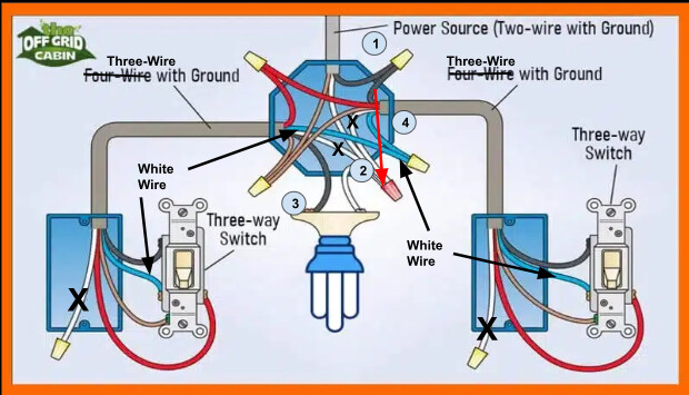
This is the best diagram I could find below, but I don't have four wires like in the diagram, just three; red, black and white, and that is the problem. Without four wires going to either box, a smart in-wall switch was out, as it needs line in, neutral in, load out, and a traveler. There was just no re-wiring scenario possible with only three wires to both boxes. My circuit uses the white wire where blue is in the diagram.

image

I decided I would just put a mini Zigbee switch up in the ceiling box, and wire the three way circuit to act as a single switch to the smart mini switch, using the switch terminal. The plan was like this:
image

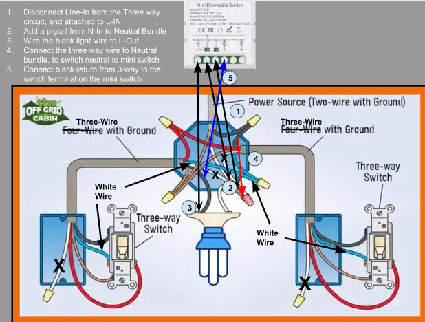
Then I decided if a switch is good, a dimmer is better, so I ended up buying a mini Zigbee dimmable switch on Ali Express for $7.50 (at the time). Note that they don't actually show the Zigbee version, the Zigbee has a single switch terminal, and a single dimmer terminal, not +/- terminals for dimming like in the picture.

https://www.aliexpress.us/item/3256806615452043.html?spm=a2g0o.order_list.order_list_main.161.43ed1802Ske3G2&gatewayAdapt=glo2usa

I got it all wired up and surprise! That switch terminal does not take a regular switch and toggle when the state is changed (like other mini switches do), it takes a momentary switch (button). I could turn the light on and off by throwing the switch off and on again, but that is really annoying. Then I wondered, what does the dimmer terminal actually do then?

So I tested the dimmer terminal. It also wants a momentary switch, but in addition to toggling on and off with a single press, I found that it brightens when held, and then dims when held again. Wow, I can get on/off and level adjust with a single button, and I can add as many buttons as I want in parallel :grinning:

So I bought a couple of decora momentary switches from Amazon:

I then totally removed the three way circuit wiring, and just wired the two momentary switches in parallel to the dimmer terminal, switching neutral. The black wire was not needed anymore.

This was the end result (note, the ceiling box with the wiring is now used for a smoke detector, as I moved the light to be recessed in the center of the hallway, so the smoke detector is included in the wiring diagram).

image

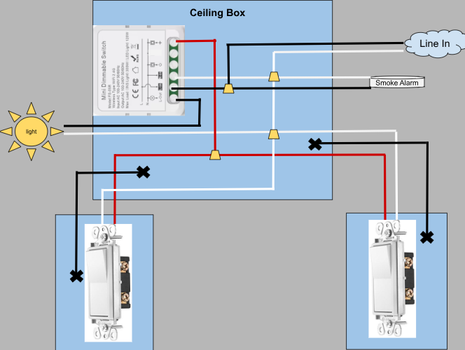
So the end result is I now have a smart hall light, with two physical switches that can turn on/off and dim/brighten the light. Not that I will use the physical switches (buttons) much, as I also added a motion sensor and automations for what level to turn the light on with motion, based on the time of day.

So, I just thought I would share this here in case anyone has a three way circuit like mine, and still wants the light to be smart and have multiple physical switch controls. It's doable! :+1:

2 Likes

I had to do that to a couple of mine. I didn’t use a dimmer as I only needed on/off. No neutral in any of my switch boxes.

Nice thing about this it still works manually if hub is off. I can sell house without removing the relay and no one is the wiser.

If I’m looking at your wiring correctly you don’t have true 3 way control from the switches anymore. If one switch is on it has to be turned off. Oops I just saw where you used momentary switches. I kept the existing 3 way and wired accordingly.

Yes, the plan was to use the 3-way circuit on the switch terminal, until I found it is not a switch terminal, it is a momentary button terminal. So that is why I had to rip out the three way wiring, though the three way would have worked on a regular mini switch that toggles the light on and off when physical state changes.

The momentary is even better, though. One press and the light is on. Then I can go to the other switch, and with one press the light is off. Hold one switch to brighten, then I can go to the other switch and hold it to dim. No more switches that appear on when off and vice-versa, like with the dumb three way, or when adding a dumb switch to a regular mini switch that takes a switch instead of a button.

If I kept the three way circuit, I would have to mimic a button press by flipping either of the switches twice to turn the light on or off. I could flip a switch to on only and it would start brightening, and then I could stop brightening by turning it off. I didn't want to play that game so I bought the momentary switches.

You can use Zooz Dimmers Zen72 or ZEN77 to do this. Wire up one with line in, neutral and load out. That will use three wires. Then the other ZEN7X needs just line in and neutral.

Then in Hubitat you set up direct association such that each dimmer controls the other. Now your light is controlled by a dimmer and each location can set the brightness level.

I do this in several locations and it works great. In one setup I have three zen77s in a so Called virtual 4way setup.

Zooz has wiring and programming info on their web site..

https://www.support.getzooz.com/kb/article/1450-how-to-program-3-zooz-switches-in-a-virtual-4-way-with-regular-bulbs/

P.s. direct association is far superior to writing a rule such that one switch state then sets state at other switch. Too much lag doing it in rules so dimming is choppy. Works fine with direct association.

3 Likes

I was about to suggest the same solution. It is simpler and should be more reliable.

I know you’ve already solved it. Nice work!

Another solution - Caseta Dimmer + a Pico remote. Only need LINE and LOAD (and Ground) where the Caseta Dimmer is installed. The pico needs no wires and its battery life is 10 years. I haven’t changed a Pico battery, yet.

6 Likes

I've had to change one after about 10 years. I can deal with that!

2 Likes

Certainly the more expensive option, but binding is not a bad solution. I was focusing more on hard wired physical controls, but binding is pretty close since it would still work without the hub being up.

The fellow who built my house was fond of three and four-way circuits - - - but not of running neutrals through switch boxes. Lutron Casetta plus Pico is the answer. Just shove the traveler wire, etc into the back of the box. (Though that is not easy when it's 12 gauge!)

Mike M

1 Like

There are smart switches with a companion switch designed exactly for solving problems like yours. Furthermore, you can add basically infinite number of companion switches.

The NEC changed in 2011 to require neutrals in all switch boxes. It is no longer permitted to just run a switch leg to a box. Some jurisdictions take a few years to adopt updates in the NEC so implementation can vary by county.

Your house must have been before the 2011 rules took effect. It's a pain to add a neutral after the fact....

You mean the kind that have their own wireless connection to the main switch? Otherwise a traveler is needed, and I only had three wires in either box. How would a companion switch needing a wire help my situation?

Here's a link to the Leviton companion switch...
https://leviton.com/content/dam/leviton/residential/product_documents/instruction_sheet/leviton-dd0sr-1z-instruction-sheet-english.pdf
It has diagrams for quite a few different 3-way wiring scenarios using a primary Leviton smart switch and up to nine companion switches with existing wiring. Several other vendors use the same approach. I assume those can be wired the same way. I don't know if you can "combine" manufacturers, e.g., use a Leviton z-wave switch with an Inovelli companion (or vice versa).

My understanding is that the companions communicate with the primary via the wiring. I've tested the smart dimmer versions of these and they seem to work well. The good thing about the dimmers is that you can control brightness from the companions and primary.

No. I forgot which company (Zooz?) have an Wired Electronic Companion Switch which required only two wires. But you have 3-wires in each box/location which is more than enough.

I'm not clear how that would work. Line, Neutral and Load take all three wires.

1 Like

@chrisbvt Nice work! ... I got lazy on mine though. Even though I had the drywall off the hallway I decided not to wire for 3 way (though I have neutral and ground in everything as ALL wiring was replaced in my house. I cheated. Since I have Lutron switches throughout the house, I simply mounted a pico controller in a box at the bottom of the stairs. Top of the stairs has the wired switch.

2 Likes

Agreed. I know my old GE Z-Wave Dimmers + the GE Accessory switches required LINE, LOAD, NEUTRAL, and TRAVELER (plus GND) at the main DIMMER wall box.

Who told you the existing 3-wires MUST be connected the way how they are?
You can easely reporpouse the meaniing of each wire. Yes, NEC Code will be broken but does it REALLY matter? If yes, you can clearly re-lable each wire in the junction boxex (just forget about standard colors, simply put a paper label on each wire). What actually matters - there is more than enoug wires between boxes for your speciffic case/application. And if buy any chance wires are in a conduit you can use old wire(s) as a rope and use whatever wire colos you want (but this will be usless effort).

I am to...o lazy to do a search but there is a combination of "switch/dimmer with two wires companion switch". These could be easely retrofit with old wireing and create 3-4-...etc. ways controls. I am not using anything like this. If I need multiple control points everything is linked logically. So far no problems at all in this area.

Did you miss that the original plan was to rewire the three way to act as a switch from neutral to the mini Switch terminal? That was complete rewiring of the circuit.

Since the switch actually takes a button input, I did the other rewiring I posted, just using the two wires from each in parallel.

Nothing in my post suggested I was keeping the circuit wired how it was.

Only with a non-neutral switch would I have enough wires, as in that case I could use the white wire for load, and red for a traveler, if that is what you mean.

1 Like