Help with wiring a GE switch and add-on switch

I’m working on replacing one of my the current 3-way switch setups with a GE z-wave dimmer and add-on switch. I’m having a heck of a time figuring out how the switches were originally wired though, and it’s not super clear to me where my line, load, neutral, etc… wires are. I’m attaching some pics of the two switches as well as the two fixtures they control.

Switch #1 is at the end of the hall, and is completely by itself. There’s only one romex coming into the box, and all three wires (white, black, and red) to be “hot”. By that I mean they both set off my pocket VoltProbe.

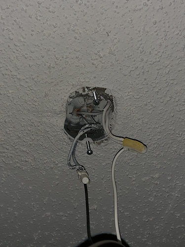
Fixture #1 (the one closest to switch #1) has one Romex bundle coming into the box. It seems to be wired pretty straight forward (black to black, white to white).

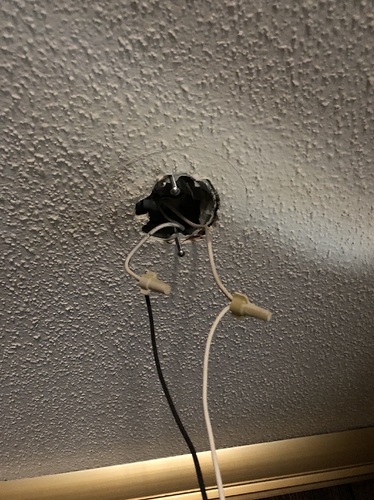
Fixture #2 has two Romex bundles coming into the box. The white wires are spliced together (along with the white fixture wire), and the black wires are hooked up the same way.

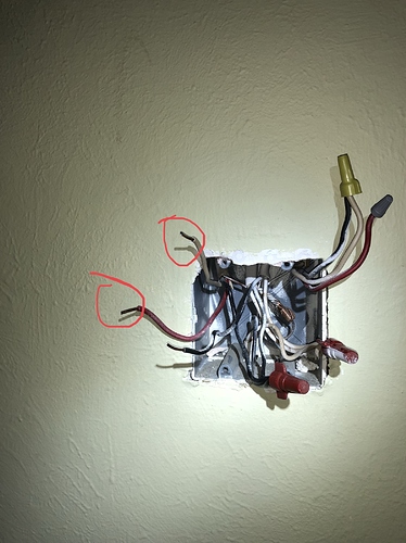
Switch #2 is in a shared 2-gang box (though the other switch in the box has been removed since converting a previous 3-way switch to a normal “one switch” setup). In this box, the white and the red wires triggered the VoltProbe, and they are both a part of the same Romex bundle. The black wire from that bundle is spliced together with the black wires from two other Romex bundles coming into the box. The black wire that was attached to the switch is a part of one of the other Romex bundles coming into the box.

I thought I had a relatively good understanding of how switches are wired, but 3-way setups have always been a bit confusing to me due to the multiple ways things can be done. In the end, for the z-wave switch setup to work, I need to have the line switch (primary switch) be wired with a line, load, neutral, and traveler connection. The load switch (add-on switch) will need a neutral and traveler connection to the switch, and the load wire from the primary switch should be spliced together with the load wire to the fixture.

I’m hoping this is less complicated than I’m making it out to be, but I just can’t seem to wrap my head around the current wiring.
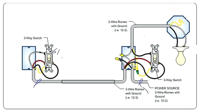
Can't be positive but from the photos it looks like this:

In this diagram:

Power source:
Black is power
White is common aka ground
Yellow is bare copper safety ground.

If you look at the switch on the left, Its power comes in on the white and is switched to either the Red or Black.

Red is switched power (i.e. power or open, aka powered or off)

Keep in mind not all electricians follow the exact color scheme, most do but I've seen some exceptions.

Most (all?) zwave dimmers require a ground, So you will not be able to put one in the left hand position on my diagram because of lack of a ground.
DO NOT USE THE EXPOSED COPPER "Safety ground" for the zwave dimmer return.

Try thinking about this in three steps..

Using the Diagram @JohnRob pasted, (1) In the Right box, Find and disconnect all three wires that extend to the left most box and keep them for later :slight_smile:

(2) Also in the right box is where you'll put the GE Zwave Switch (or dimmer). It needs 3 wires, Hot, Neutral, Load. With those 3 wires, the switch will work the light if you're doing this for real, and not just following along in your imagination :slight_smile:

The adhesive tape over the 4th screw wouldn't be touched.

OK, now you have all three wires that extend over to the right most box - you can wire them ANY WAY you want, and you do just that.

(3) The Auxillary switch from GE goes into the left box, and only needs two wires, one on each of it's 2 screws. [me, I'd use that white wire for neutral and that red one for the traveller, and then the black is unused.] In the Right box, wire them up to meet the needs of the Aux switch: neutral, and traveller (going to the adhesive taped screw.)

You have one "spare" wire going between the two boxes. Just cap the ends off with wirenuts.

NOTE: I've completely ignored the bare ground wire, because I assume everyone knows how that is used.

1 Like

This video has an interesting approach to determine your load wire. Maybe it helps.

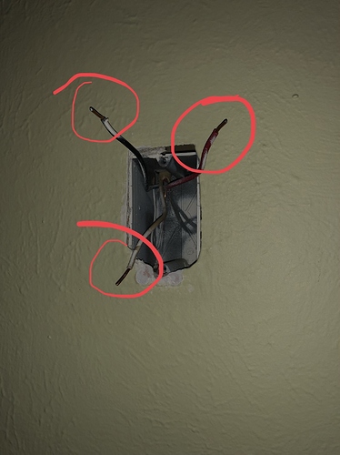
@murray.sean.d In your picture of what I've called your "right box", you have a bundle of 3 Black wires wirenutted together.. that's HOT. You also have a bundle of 3 white wires wirenutted together... that's neutral.

Seems like, based on your red circles, you've identified the white and red that are needed for the GE Add-on switch. Me, I'd add that white to the bundle of 3 whites and use that red one on the 4th screw (adhesive tape) on the ZWave switch (or dimmer.) The black one that's near the circled pair, I'm guessing you've already identified it as going up to the lamp assembly. That's the Load wire, if my assumption is correct.

These ZWave switches and dimmers are pretty deep, in my opinion, making it a struggle to get wirenuts packed well at the back. With an entire switch missing in your case, You've Got It Too Easy!! :smiley:

On the "Left box" as I've been calling it, wirenut the black to prevent shocks and shorts (because it's hot as it's wired in the pic, and that's OK) then wire the white to the common of the Add-On and the Red to the traveler and I'd say you're all done.

This topic was automatically closed 365 days after the last reply. New replies are no longer allowed.