I am wanting to work on a little project to see if I can use HE to control my old steam shower. The steam head unit uses an RJ-12 connector for control. I am no electrical engineer and a noob when it comes to schematics, but from what I can make out in the diagram below, it seems like I may be able to use a Zen16 to control it? If anyone has the expertise and is willing to help me explore a new skill, please give me a DM. I may try and integrate a temp sensor that can withstand the heat. So any suggestions there are appreciated as well. Thanks!
1 Like
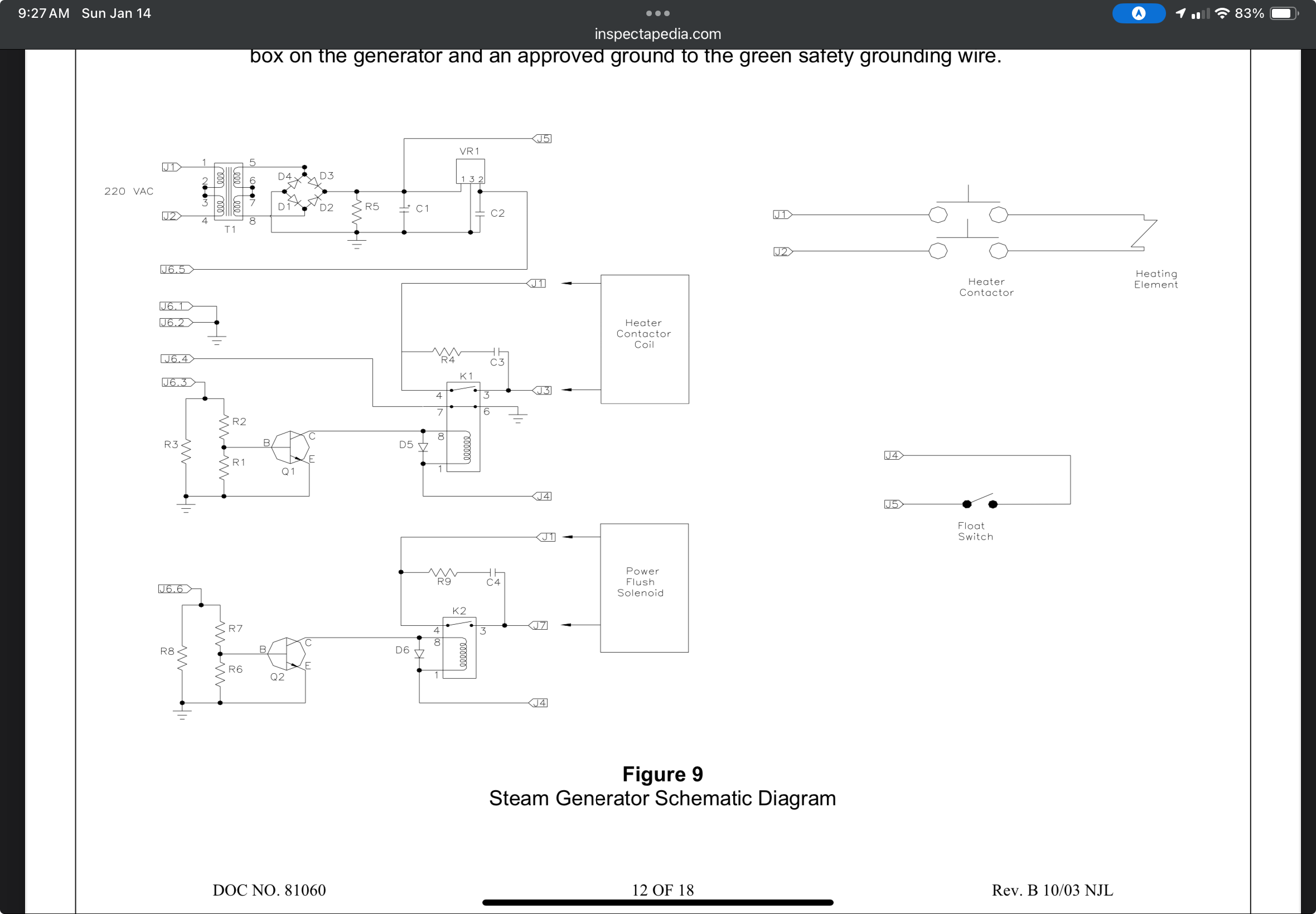
Just guessing, I'd say the RJ-11 is "J6.x" and is 6 pins. From the schematic, there's no clear sign of which end is pin 1.
Pin 4 is a sensing contact and will need a pullup. It seems to use the NC contact of the Heat Contactor control relay. It's 0v when the heat contactor is de-energized. It would be VCC (through the pullup) when the heat contactor is energized.
You'd connect pin 5 (VCC) to pin 3 to energize the Heat Contactor relay, and connect the same pin 5 (VCC) to pin 6 to energize the Power Flush Solenoid relay.
The schematic does not identify the voltage that is on pin 5. Make sure whatever you use to control this is able to work with the actual voltage.
1 Like
Curious, what brand steam shower you have. We have one that also doesn't natively support external control and I've played w/the idea of integrating it off and on.
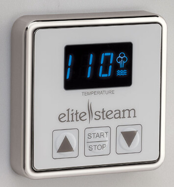
We have an Elite Steam (since bought by Delta and renamed SimpleSteam) setup w/a couple wired control pads (in shower and outside bathroom) that link up to the steam generator. I haven't looked into any details on the wiring yet, but thinking that this will be interesting to watch... ![]()
Wow, thanks for the speedy response and willingness. Thanks and sorry in advance for my noob-ness. But a couple follow-up questions.
— I don’t need the powerflush feature (my head unit doesn’t have that) so is it really simply turning the steam on and off by completing the circuit between with Pins 5 &3? (If this works I would also bypass the existing controller in lieu of my relay to just turn on the steam and turn it off base on time and temp in HE)
— I didn’t know what a “pull up” was but went reading. Looks like it it is a resistor that normalizes voltage so that you can cleanly asses sensor state? (feels a little like an EOL resistor in alarm systems?) But still a little lost of what pin 4 does if the existing controller is not attached. Do I need Pin4?
— and finally how do I best safely determine voltage on pin 5. Just a multimeter to 5 and what [pin 3?] (told you I was a noob, but happy to learn a little while doing it.)
Thanks again…
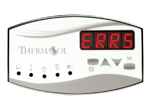
An older Thermasol
1 Like
Were you able to make any progress on the steam shower control?
Short story long - I have a built-in Kohler steam unit and a component went on the unit that I have not been able to source and it has been sitting disassembled in the basement for ~2 years waiting on me to have time. Someone locally remodeled their bathroom and was selling a steam generator.
I figured that was a faster path than waiting on me going on the history, so I hopped on it - it is a ThermaSol unit. They also provided the controller - which I thought I did not / would not need - it looks identical to the one in the picture.
I connected and plumbed the replacement in (completely different shape and size, this sentence is a lot shorter than the unanticipated effort it took) flushed the water, connected the controller and turned it on. Nada. Nothing. Zip. Blank display.
Thankfully the seller included the controller - that I did not think I would need - I plugged that in and put it through its paces and it did all it was supposed to. Since they call all the units "DTV+" I assumed, incorrectly of course, that there was some standard or they were interchangeable. Further investigation revealed a lot of "only works with xxx" across vendors. I find it hard to believe that they independently all developed controllers with such similar - and really not fancy at all - functionality. (Complete aside, why do Kohler, ThermaSol - frankly most of the brands - use tiny physical push switches with sharp points, then throw a film of plastic over it like it was planned to break - could just put a round thin steel disc on the adhesive plastic, seriously.)
So now I have a dilemma - try and reverse-engineer the ThermaSol and then the Kohler (which I may not even be able to do) to see if they just use different wiring, or attempt to cut out the existing Kohler unit (which is square and looks better IMO) and put the ThermaSol in its place. Or perhaps both in reverse order. If not a simpler wiring difference, perhaps there is some handshake or code they share, but the fact that nothing lights up implies power was not even there.
I noted on the ThermaSol that they support a "digital" controller like the one above as well as an "analog" controller which is really just a switch unit. I think 6 wires and 4, would have to check, but likely just a combination of contacts to do nothing, one thing, one other thing, both things - assuming two of those wires switch to ground. I was also gobsmacked by the prices of these "controllers" - $500 - $2000, averaging around $700 for replacements and limited compatibility even within a vendor. This is a basic circuit with 4 multi-segment LED display and a thermal sensor in a water/steam proof package ... so what would the cost be, maybe $50 if including the nickel or whatever surround, the potting and additional testing. It is like they are begging someone to make a universal replacement.
So, with the price of the controller, the fact that there are many of these "dumb" ones still working after several years (I guess there is some ruggedness there) and the "you-can't-have-a-choice-we-are-going-to-make-the-simple-proprietary-and-make-you-pay-just-because" it is certainly ripe for some project to do more. I could see where having something between the controller and the unit could give great options to both pass through a unit (of whatever brand and vintage, configurable) as well as support the "fire up the boiler at 6am".
So, count me in as another willing participant - but one with a lot more ideas than time or sometimes skill/capability. But I do tinker and with some guidance could contribute to the collective gain.
No progress. I need a little more confidence from an electrical engineer type to help me with the schematic and what is needed. But still very interested.
Can you measure voltage between pins 2 and 5 and report back? This will also clarify which end is pin 1.
I likely won't get a chance to take another look or tinker until the weekend, but did some more digging last night and building a couple hypotheses to hopefully work through some of the mystery.
First item, this particular controller is in fact an analog controller - the last in their line, the so-called "Elite" controller. See here -> https://support.thermasol.com/hc/en-us/articles/360030895892-Analog-Control-s
So, it is not "communicating" with the generator - it is either some very simple on-off signals or pull-up / pull-down values. My working theory is that the clock, timer and temperature set is within the controller unit itself (i.e., not on the generator) - so other than power the wires are to turn on or turn off the unit (as decided by the remote control side by time or temperature), likely provide an input on the temperature where the unit is to guard against overtemp and I am aware it can also initiate a power flush for units that have that (mine has the manual power flush). So, likely power, generator on-off, temperature (likely variable resistance) and some pins for some other function.
This also means there is a chance you could read off the temperature and switch the unit on and off by putting something in the path - but will not have a temp set point or timer or any of that. Perhaps a simpler solution would be to have a switch pusher that just pushes the S button ... but I don't think they would like the steamy environment.
But here is where things may look more interesting ... looking at another doc, all of the units, including the much older ones like the one I have (a 1J model 240 ... guessing quite dated, non-pro line) have both a JTAG-ISP port and a CAN port on the PCB, look at p40, 41 in this doc -> https://www.saunaplace.com/wp-content/uploads/2013/03/Thermasol_Installation_Guide.pdf?srsltid=AfmBOooTmtppq_vTJ8eQboV3Dti3VWcI-CMQovihd8XYis7W_CNjEEU0
The JTAG is likely what they use to test and program the unit and should give the lowest level access to the unit, but what is interesting is the CAN port. CAN is a Controller Area Network and is the same mechanism used on all modern cars for connecting sensors and activators, etc. Each "device" registers on the network and can send and receive blocks of data.
So, potentially, you could put a device on the bus that can read the current state, send on-off commands, read the value of all the connected sensors, etc. That would be a lot more useful! This could also be why certain digital controllers only work with that vendors devices - they can code the address and send only to their addresses or have different recognized addresses that are hard coded to the controller. More to come.
Referring to the wiring diagram that @jeff11 posted above, I’m thinking a Shelly Plus Uni would work… but not sure what the working voltage is. Also, I’ve never checked if the plus uni has an internal pull up available on the digital inputs… but I have one here I can play with. In looking at the doc you posted, I’m not sure it would work for you… but I’m not an expert on CAN.
I am not an expert (or even close) on CAN either, but have a working knowledge of how it works (kind of like a messaging bus, all nodes broadcast individual nodes select what to listen to) - then it made sense to me why they would use it and the potential of being simplified as well as extensible. Only way to really know would be to sniff the CAN bus and see what is going on and if it can be leveraged -- and I don't have any digital controllers so this may even be a project for someone else.
That Uni board looks interesting, wish someone would make similar boards with Zigbee or Zwave vs Wifi, but perhaps in time it will merge with Matter. Looks like it may be easier to test/prototype with than just a stock ESP32 ... ESP32 does have a built in CAN controller, but no transceivers, so also needs more pieces if that is even a route. But on the analog side that Uni board looks great for quickly connecting things without too many cycles.
For some reason can't get this challenge off of my mind ![]() - but analog control is definitely feasible - they create a test cable that will turn the unit on and off - https://support.thermasol.com/hc/en-us/articles/115000773108-Test-Kit-Instructions
- but analog control is definitely feasible - they create a test cable that will turn the unit on and off - https://support.thermasol.com/hc/en-us/articles/115000773108-Test-Kit-Instructions
That is either a specific wire connection or a resistor across some wires. Also, when operating with the external unit and the internal unit through a splitter, the external will also activate the internal and gets some analog feedback for time - so if the external unit can be emulated then the interface can be near the unit, in the path and not need any messing with the control unit.
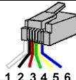
5V - on pin 5. RJ12 so standard pinning - if copper pins facing upward, tab on the back and cable runs to the right, pin 1 on the bottom, 6 on top.
Connecting pin 5 and pin 3 will engage the steam unit without the controller connected (and disengage when disconnected). With the controller connected, a momentary contact of pin 5 and 3 engages the steam unit and activates the controller as does a momentary disconnect of line 4 between the controller and the unit. My guess is that one of these methods are used when pairing both internal and external control unit. Either way, this provides a mechanism to automate the pre-heating of the unit and you could read off pin 4 for current state.
Kudo’s to @csteele for pretty much calling it all from the base diagram.
This should be easy then. I think you could get away with a standard Esp32 board (and some additional parts to handle 5v control), but personally I would still use a Shelly plus uni (which is basically a glorified Esp32) running tasmota. The only thing I’m unsure of is if the Uni has an internal pull-up on the digital inputs. I can check when I get back in town - unfortunately in a week and a half. If confirmed, the Uni should be a breeze to set up.
Edit: You can install tasmota firmware pretty reliably OTA on the plus uni. Out of a half dozen, I’ve only had one fail during the initial tasmota safe boot “migration” but was able to recover the process OTA.
Wow. As a noob, I love that 'smart others' have made so much progress. It is fun to try and follow along. Also, as a noob, not sure I confidently know how to proceed next. (No experience with Esp32 or Uni at all.) So I have some basic questions and concepts I want to make sure I understand...
Here goes:
1-Because there are 6 pins, this is an RJ-12, yeah?
2-If I simply disconnect the thermasol external controls and plug in an RJ-12 lead, cut off one end and connect pins 5 and 3 to any simple Z-wave relay? For example, I have experience with this Zooz Zen16 in my Garage setup. Attaching pins 5 and 3 to R1, R2, or R3 on that unit, and then turning on and off will turn the steam on and off?
3-And perhaps the noobiest of noob, but just to confirm, this is how I identify the pins and leads?
Thanks again all for all your smarts!
I can help you with the wiring and setup if you’re willing to give it a shot. I just don’t own a steam shower, so I don’t know how it operates - but the wiring diagram seems easy enough to read and simulate on a test bench.
If you decide to use a Shelly plus uni, you would connect 5v power from pin 5 to the gray wire on the Shelly as well as one side of each of the digital output relays (one black wire of each relay). Then connect the green wire to pin 2. Then you would connect the other black wire off one relay to pin 3 and the other black wire off the other relay to pin 6. Finally, you connect pin 4 to the orange wire (assuming there’s an internal pull-up there to use - I’m guessing there is).
As for installing tasmota on the Shelly plus uni, it’s a piece of cake. Just connect the Shelly uni to a 5v power supply (green and gray wires) or to a 12 or 24v power supply (red and black wires). Once powered, connect to the Shelly’s WiFi network and go through the setup to connect it to your WiFi network. Once connected to your wifi network, run all the available Shelly firmware updates. Finally, carefully follow the instructions on GitHub - tasmota/mgos32-to-tasmota32: ESP32 Mongoose OS to Tasmota32 OTA updates for Shelly.
Once you complete those instructions and get the tasmotized Shelly running, you shouldn’t have to do anything else on the Shelly if you don’t want. You should be able to install the community tasmota driver on HE and connect directly to it. The universal multi sensor double relay driver should pick it up right out of the box.
When I get back in town, I can test the whole process and mock up a similar configuration on my test bench and make sure it all works and then post back.
To answer your questions:
I would say yes
This should work as well… but no status reporting.
If you measure voltage across pins 2 and 5, that should tell you pin out. If the voltmeter reads positive 5v, then whichever pin the red probe is on is pin 5. If it reads negative, the red probe is on pin 2.
I am comfortable with the Zen16, but I am up for trying to learn about Shelly and Tasmota with your helpful instructions. So, I will be interested in how it goes on your test bench. I am also curious about other benefits with Shelly. In the other post, you say Zen16 should work, but with no status reporting. What benefits do you anticipate from the Shelly approach? Is there data or monitoring from the unit you anticipate (assuming I don't use Thermasol external controls)?
Pin 4 appears to provide current status - for when the steam shower is controlled manually (not through HE). A zen16 won’t pick that up (easily). A zen16 will only give you control, but no status/confirmation.
If you want to get more advanced later, you can create one virtual device (either on tasmota/shelly or on HE) that provides control and status.
Ok, that makes sense.
I have just tested by connecting to a Zen16 ( FWIW, the cable I used was like the test cable, pins 3/5 on green/black). Steam is running now, and on/off-able by Zen16! So there you go! I will be interested in your bench test with tasmota/shelly. It may tempt me to try and learn a new skill and work with that as a new project. Thank you again!