I've always wanted to hack a Zigbee lightbulb, but have hesitated for a couple of reasons:
- I'd have to destroy an otherwise perfectly good bulb
- Bulbs were often difficult to open
- Modules were often difficult to extract
- Posted "How-To" articles couldn't explain how to pair and reset the separated Zigbee modules
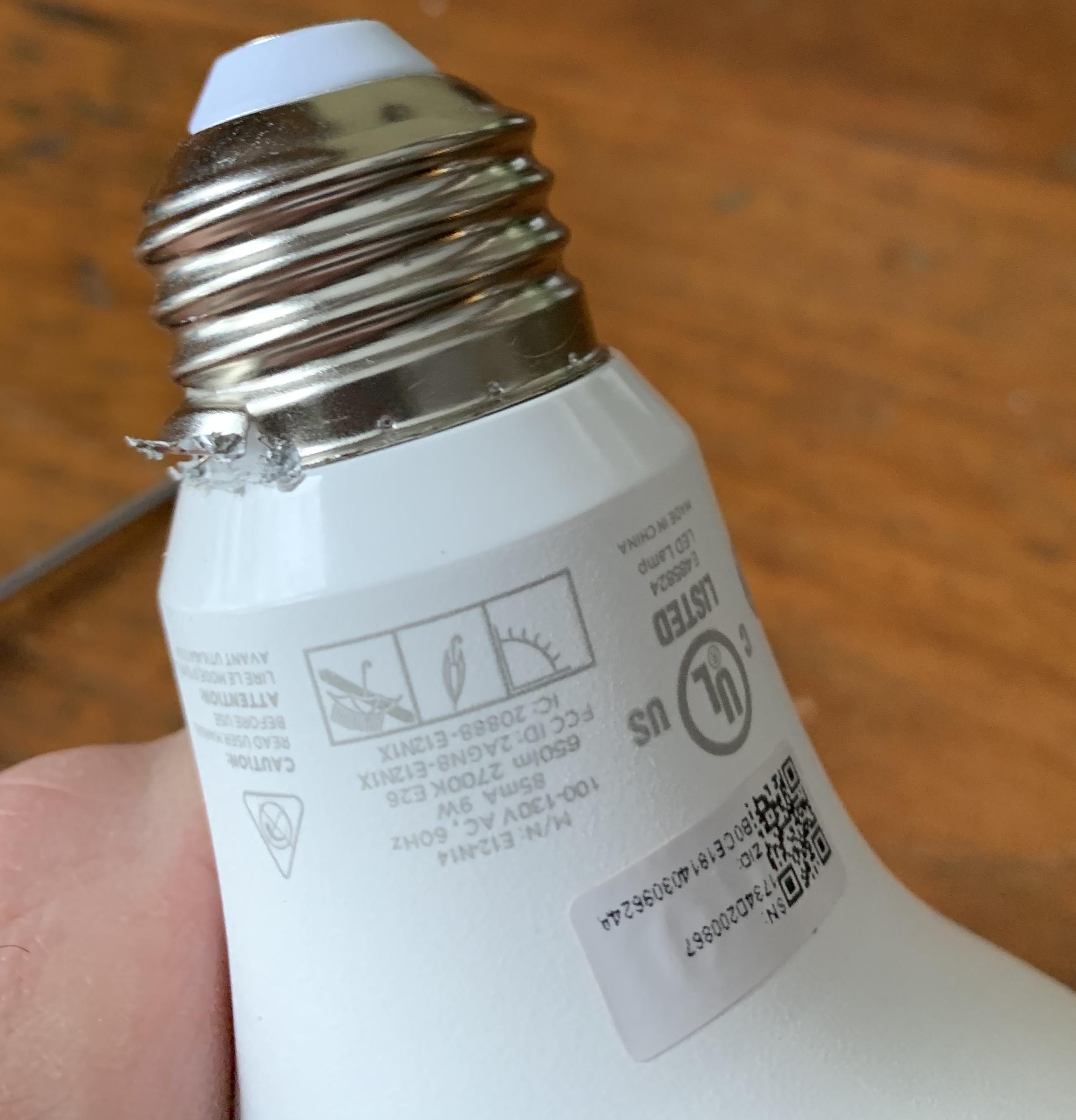
While shopping Lowe's Black Friday deals, I came across some Sengled BR30 Zigbee bulbs on clearance for $5.99 CAD. Now, I have no fixtures in my home that use BR30 bulbs, but I figured if the incandescent bulbs in my deck light ever decided to die (They've been going for the 19 years I've owned this house, who knows how long before that), then I would remove the smart switch and use these in their place.
To my shock, these non-repeating Zigbee HA bulbs, that can be directly paired to Hubitat Elevation with no ill effect on the Zigbee network, actually rang up at $3 CAD per bulb! So of course I went back and grabbed more!  And at this price, I had no reservations against potentially destroying at lease one bulb for the sake of exploration.
To my surprise and delight, these bulbs are incredibly easy to hack. I mean, really easy. After figuring out what was required, I can open the bulb and extract the Zigbee HA module in less that 3 minutes. What's even better is that it can be driven by a standard 5v DC source, and you can trigger a solid state relay, allowing you to close dry contacts for just about anything.
These modules cannot be battery powered since the original intended use case is mains powered only, they draw 30mA at 5v DC, and so are not suitable for battery powered use, but are easily powered with a common 5v DC USB power adapter.
How to open the bulbs
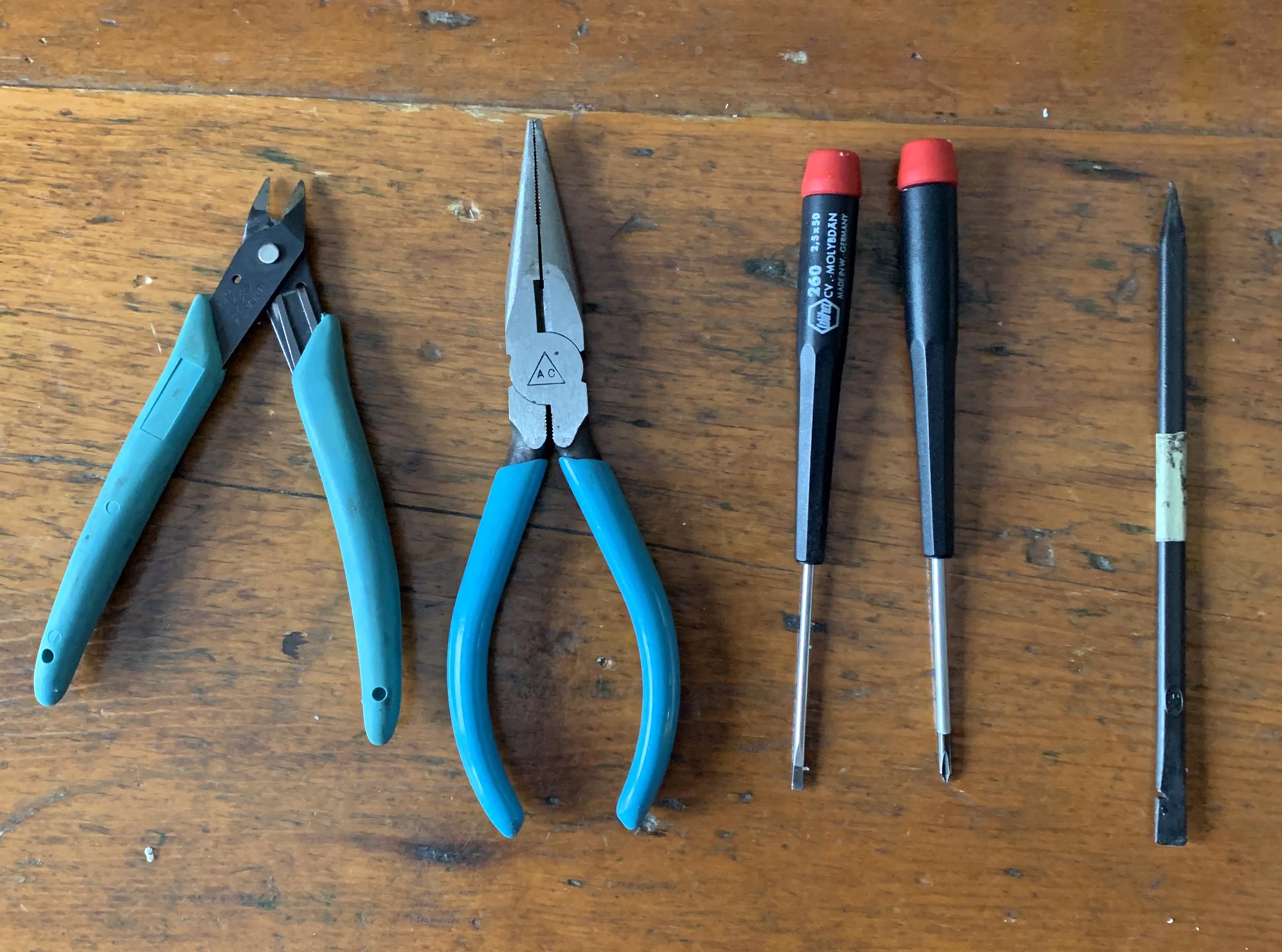
Recommended tools to make the job easier - (left to right) Diagonal cutters, needle nose pliers, small blade screw driver, small philips screw driver, plastic spudger
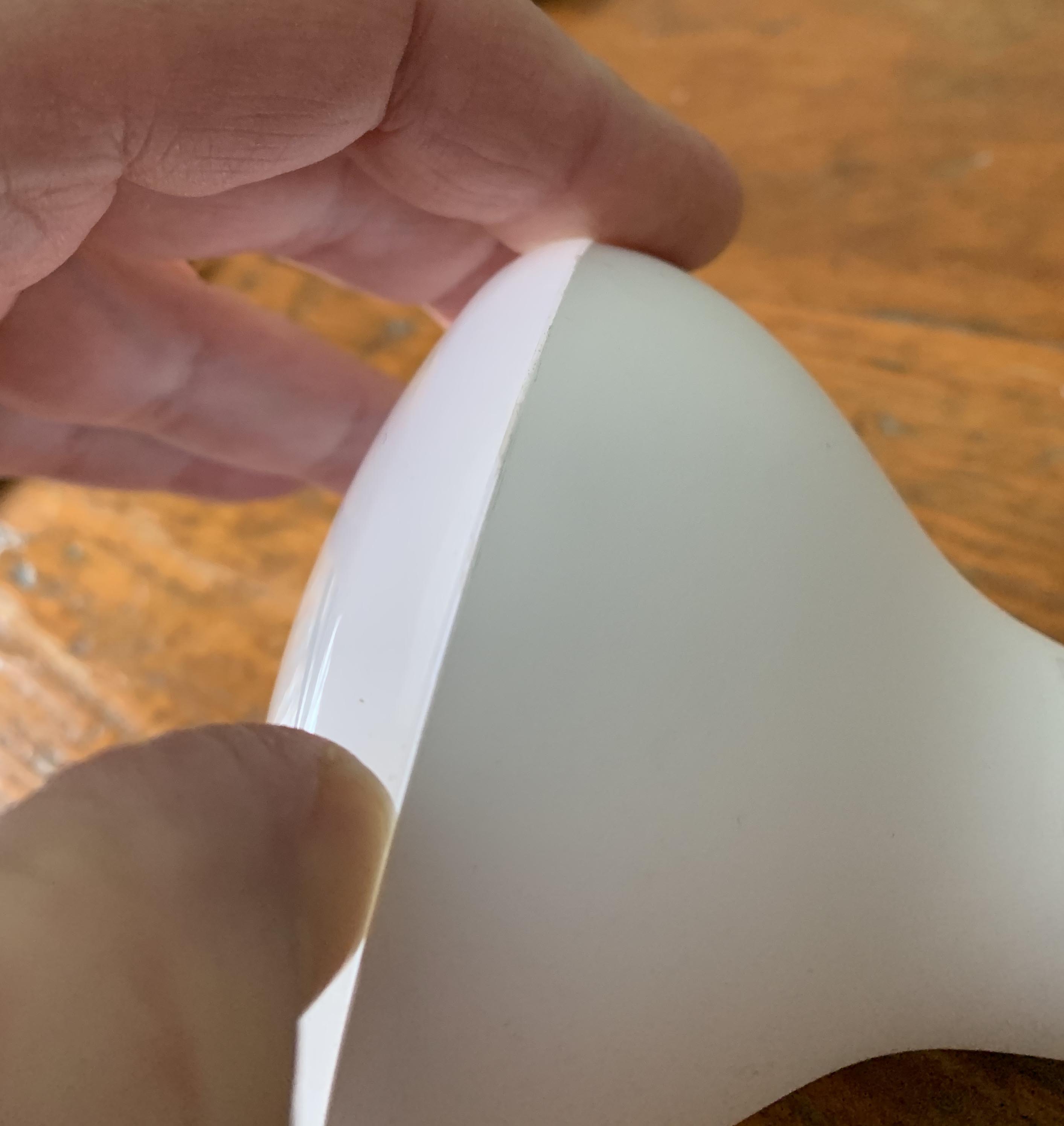
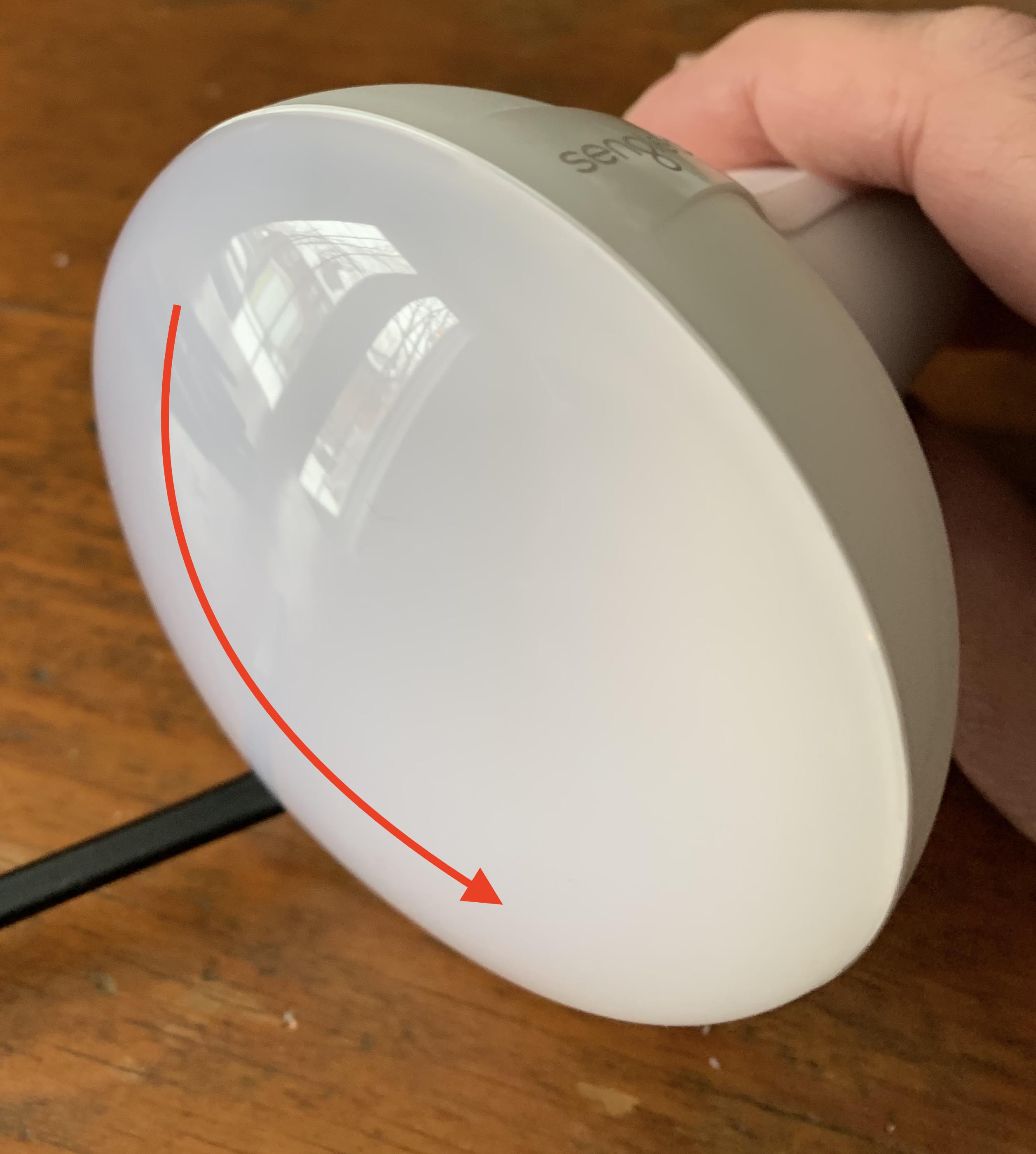
- Start by using your thumb nail and run it around the circumference of the bulb until you find a spot where there is a small gap between the defuser and the bulb housing. In the two bulbs I've opened so far, this has been very easy to find.
- Once a gap is found, insert the blade end of a spudger into the gap.
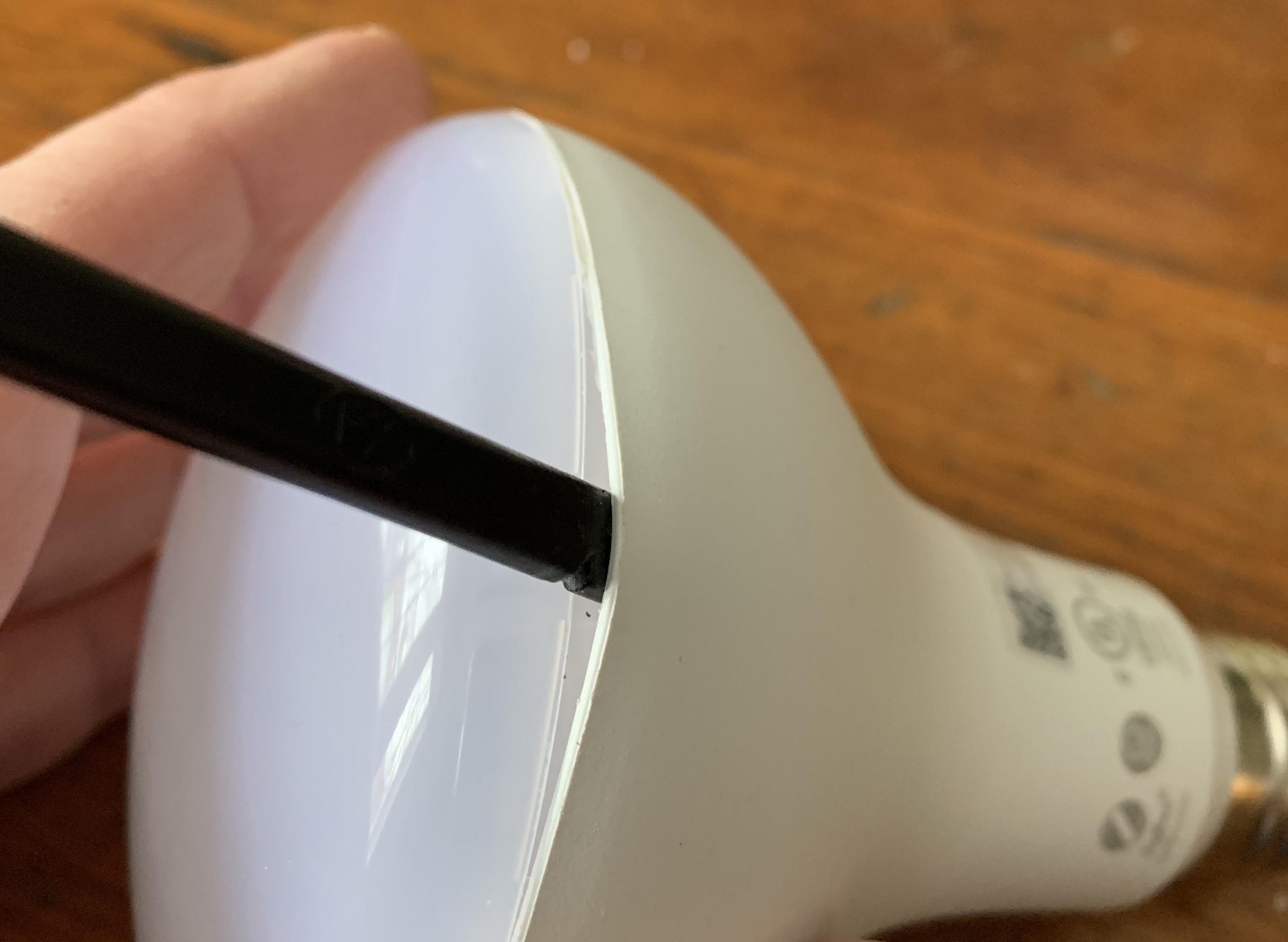
- Work the plastic spudger around the circumference of the diffuser. The sealant/adhesive used on the diffuser is very easily parted from the housing. There are four locations on the diffuser where it also clips to the housing. They will become evident as you begin to pry the diffuser away.
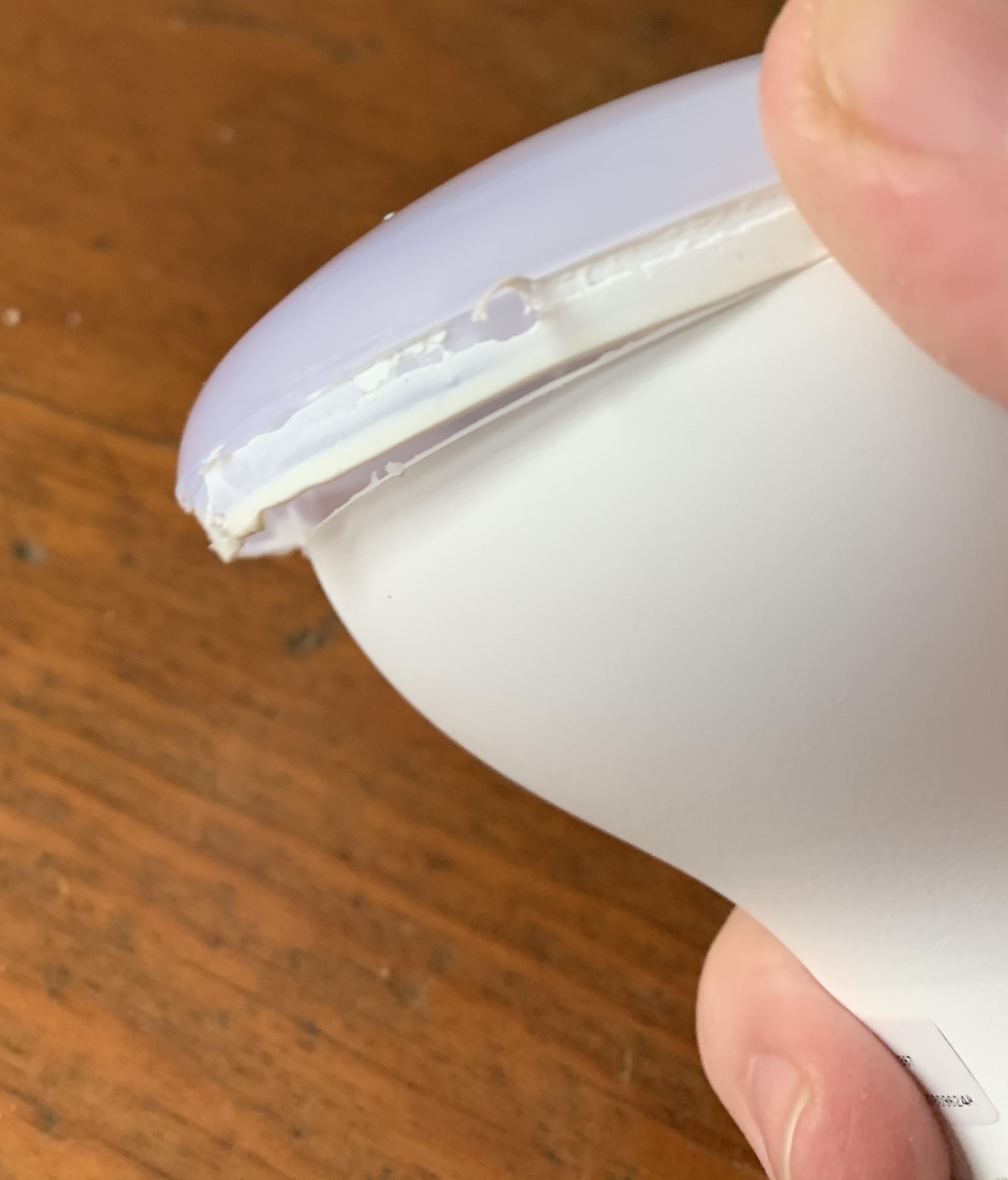
- Pry the diffuser away from the housing and you will see how it was sealed and clipped in place
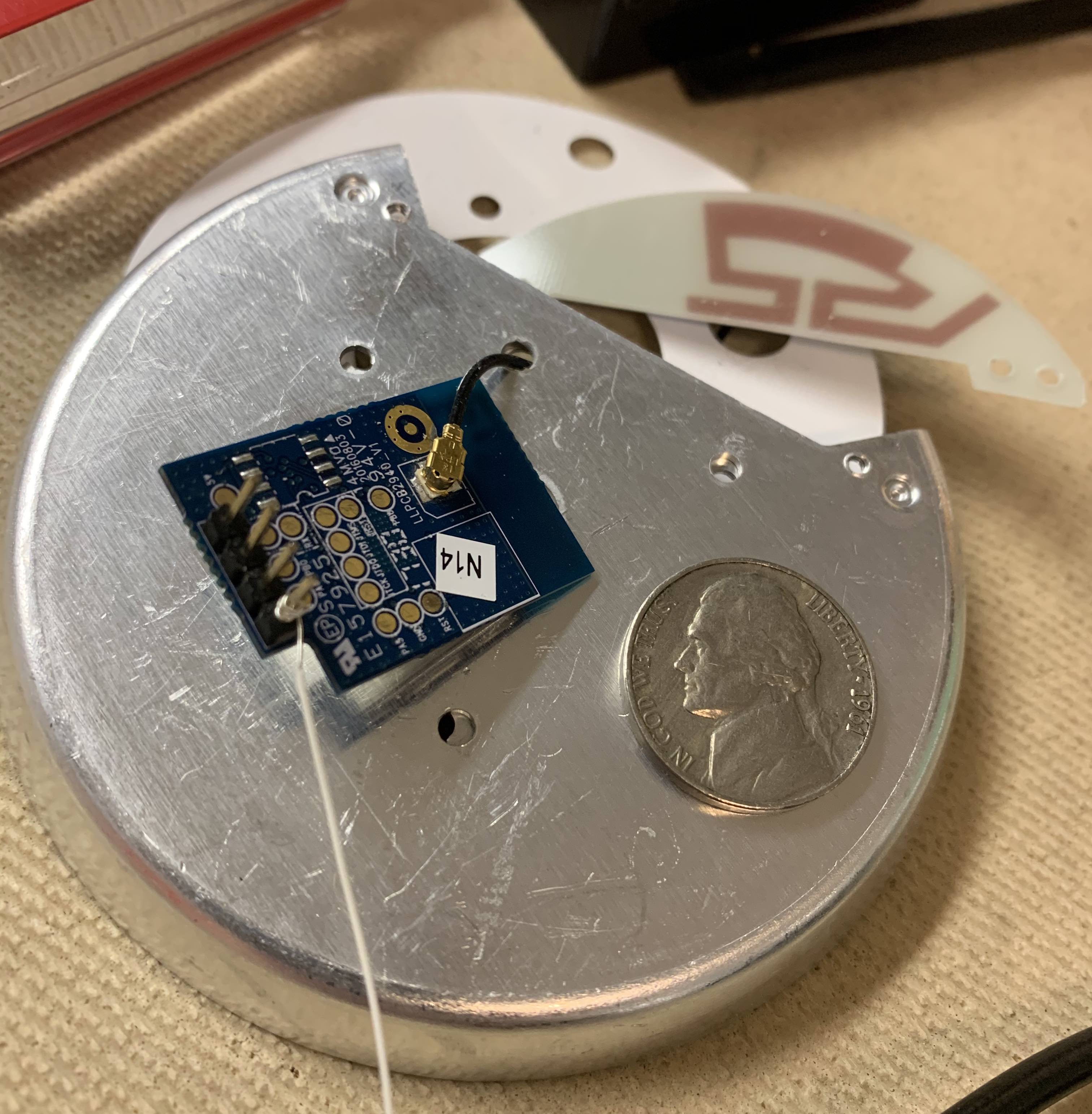
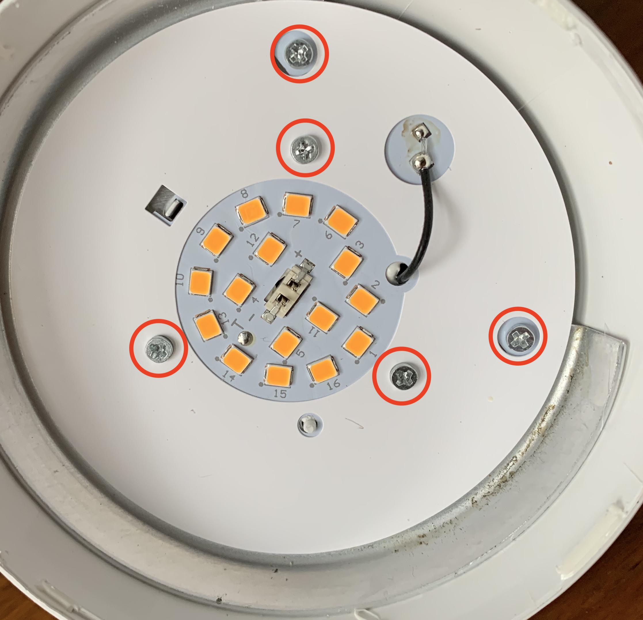
- There are now 5 Phillips screws (circled in RED) that must be removed. The 3 in the center hold the LED heat sink to the housing, and the 2 outer screws hold the Zigbee radio antenna to the housing.
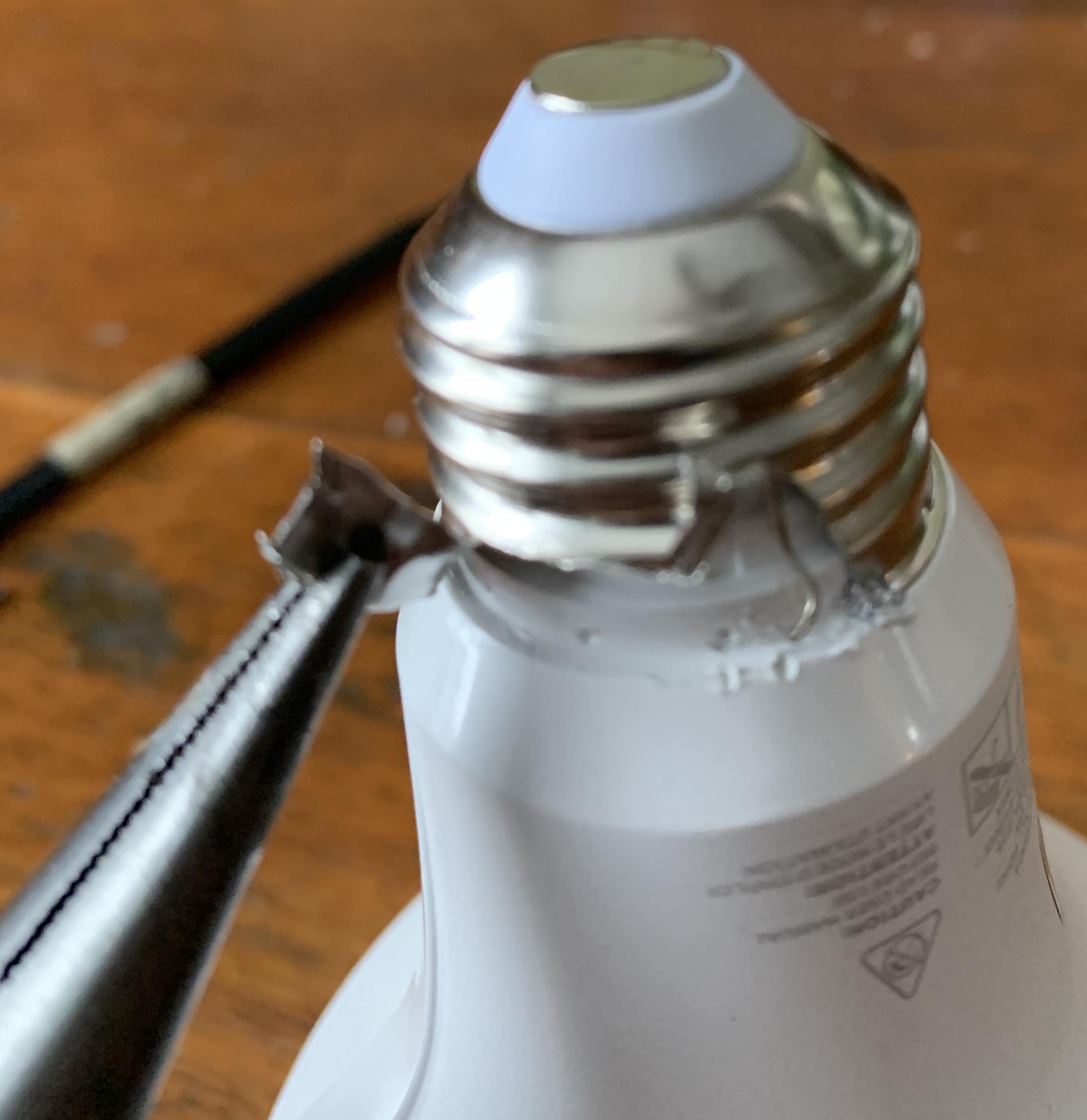
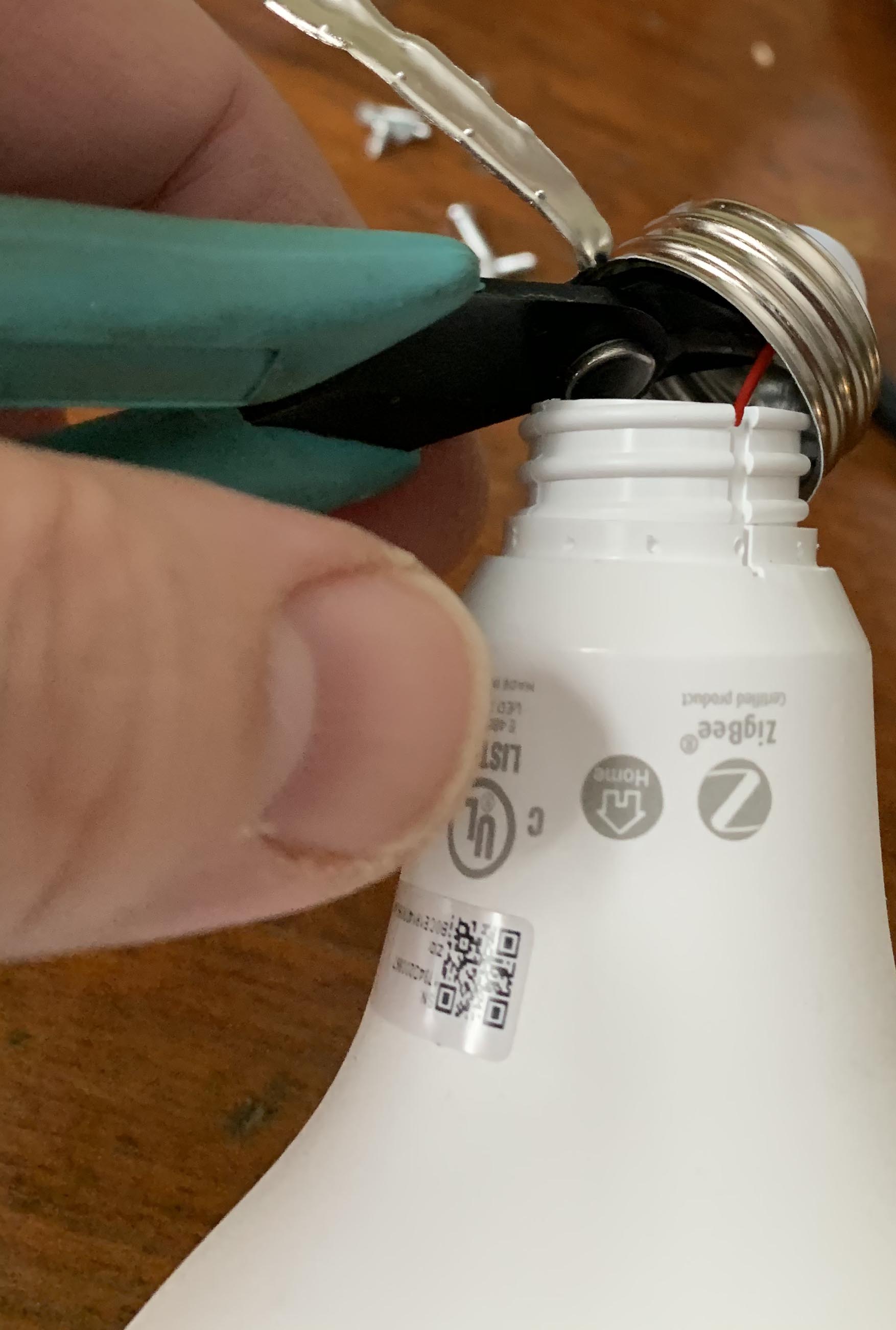
- Now the Edison screw base must be detached from the bulb housing. The Edison screw is crimped at several points to the housing. Removal is simple, but be careful here and wear gloves so you do not cut yourself. Start by using a small flat head screwdriver to pry up at one of the points where the Edison screw is crimped to the housing. I've found that there will be a slight gap where the neutral wire is sandwiched between the housing and the Edison screw, and this is an easier place to start prying.
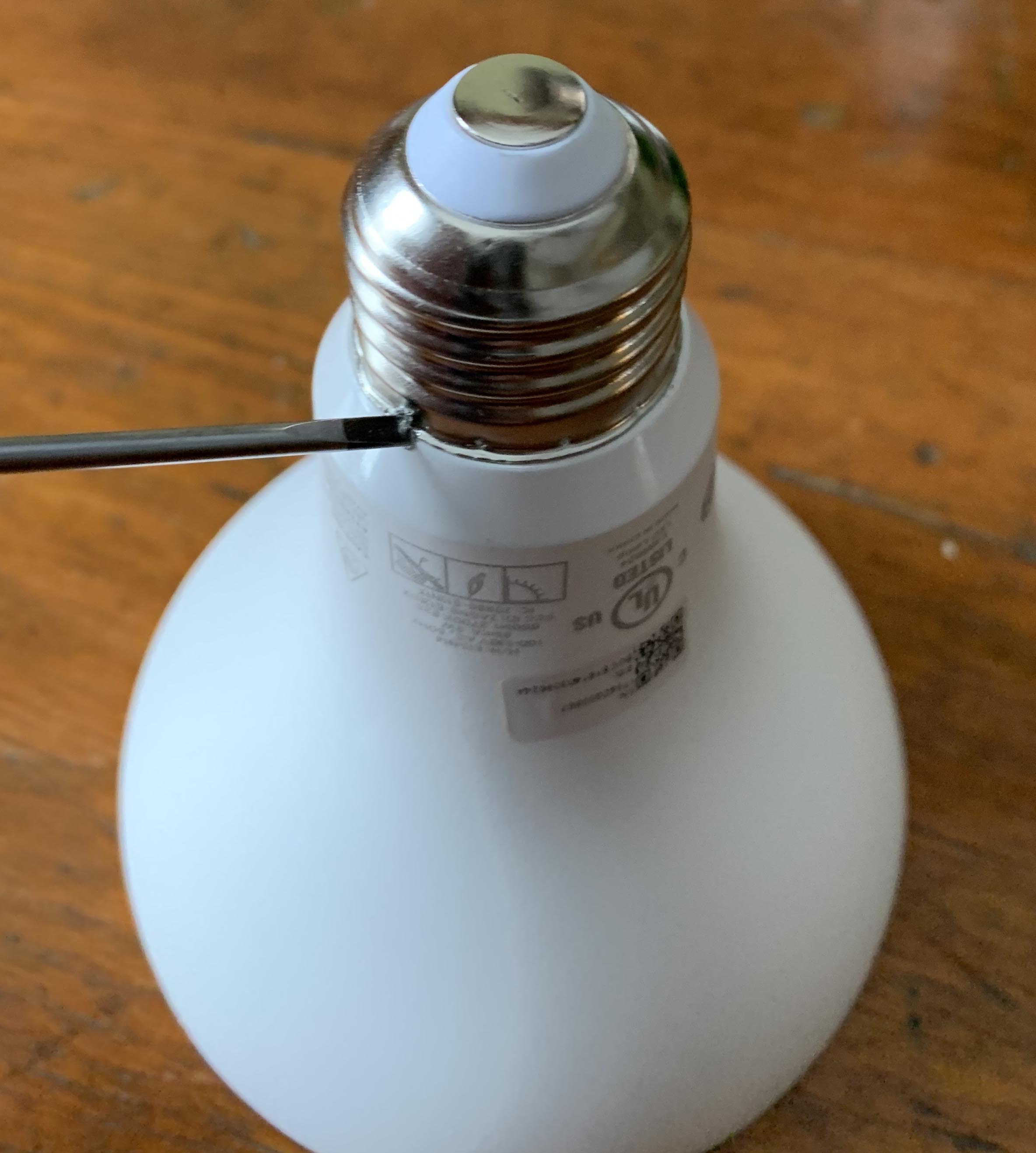
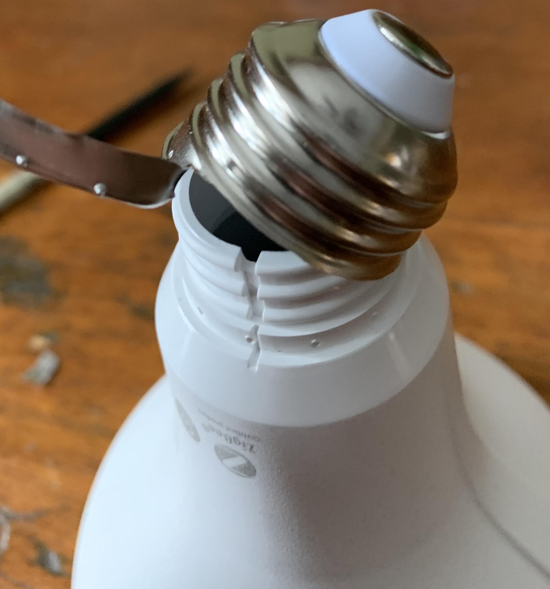
- Once you get a bit of the Edison screw pried up, you can use needle nose pliers to simply peal it back, and this will release it from the housing.
- Now that you have the Edison screw detached, you can see where the HOT wire is soldered to the base of the Edison screw. Simply take diagonal cutters and cut the wire from the base.
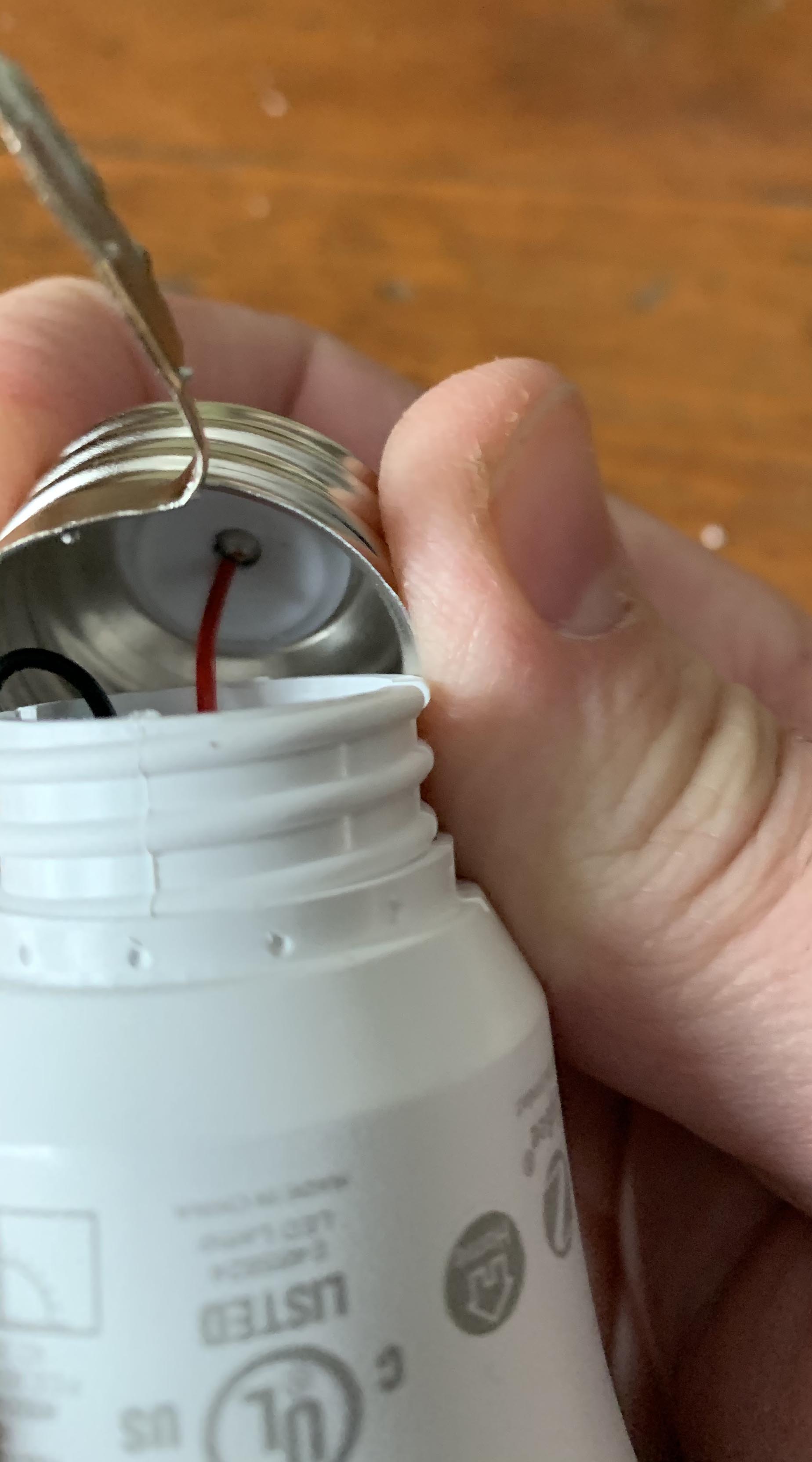
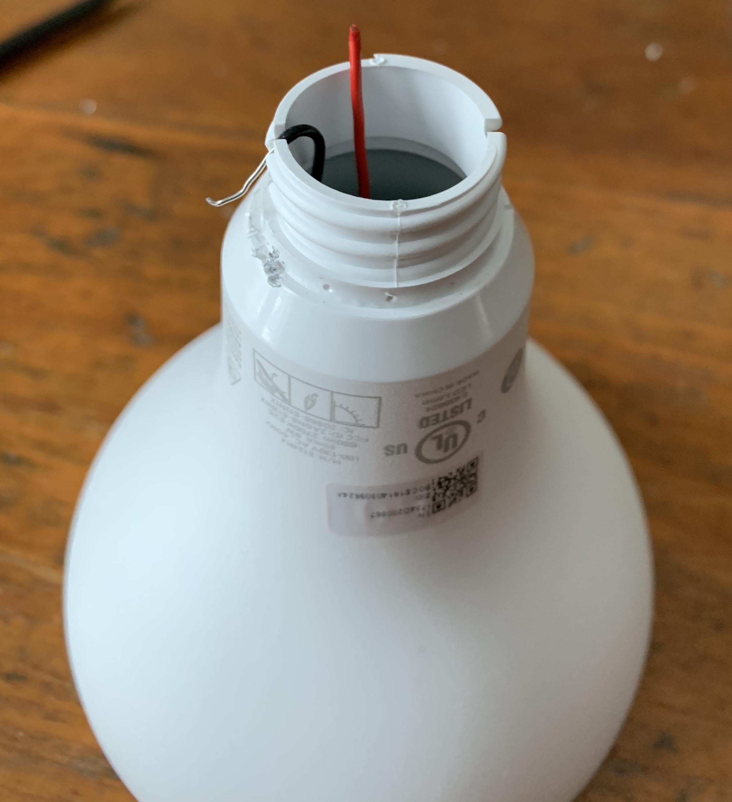
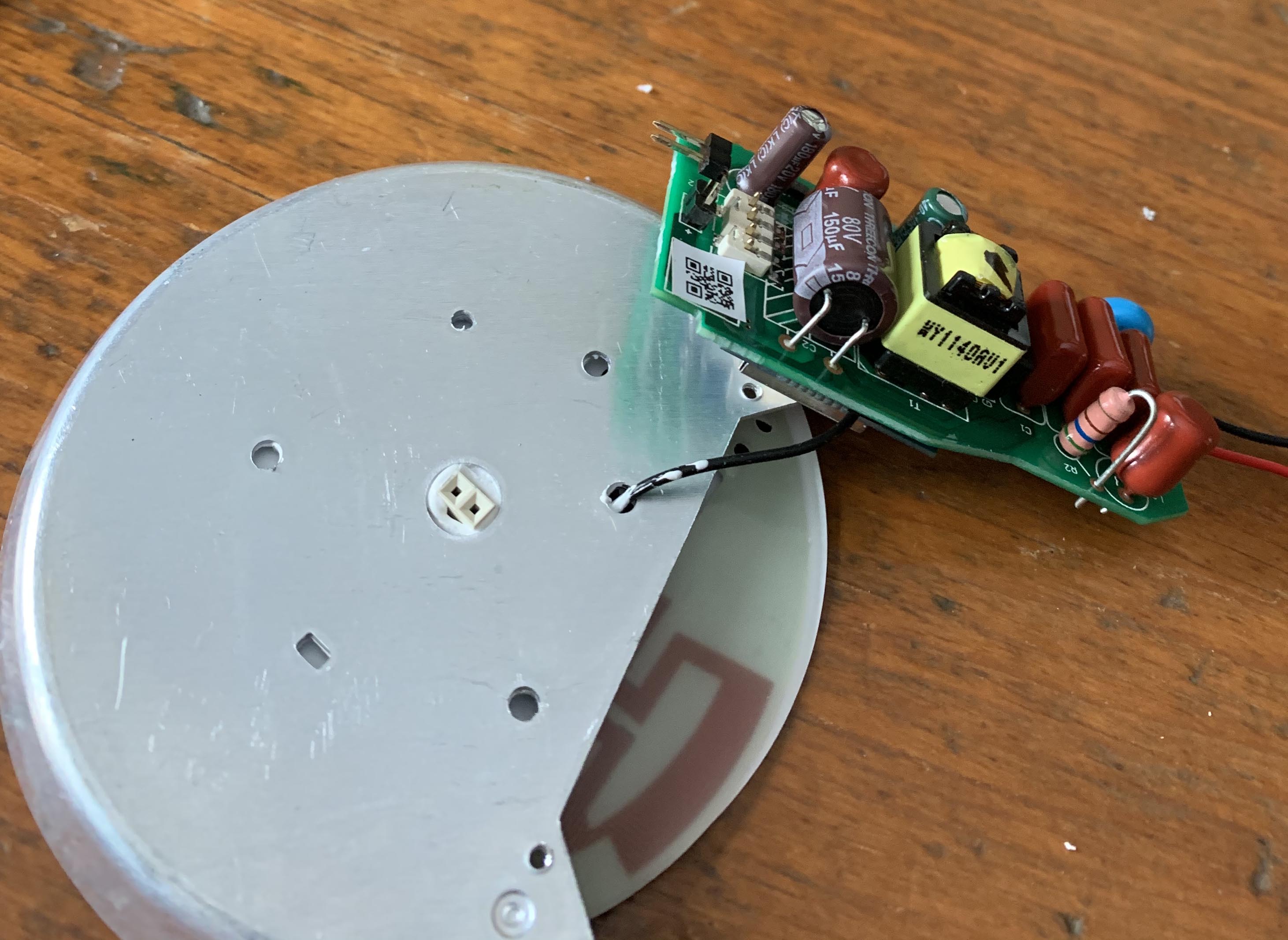
- Now just lift up on the housing to reveal the LED driver board with the Zigbee HA module attached.
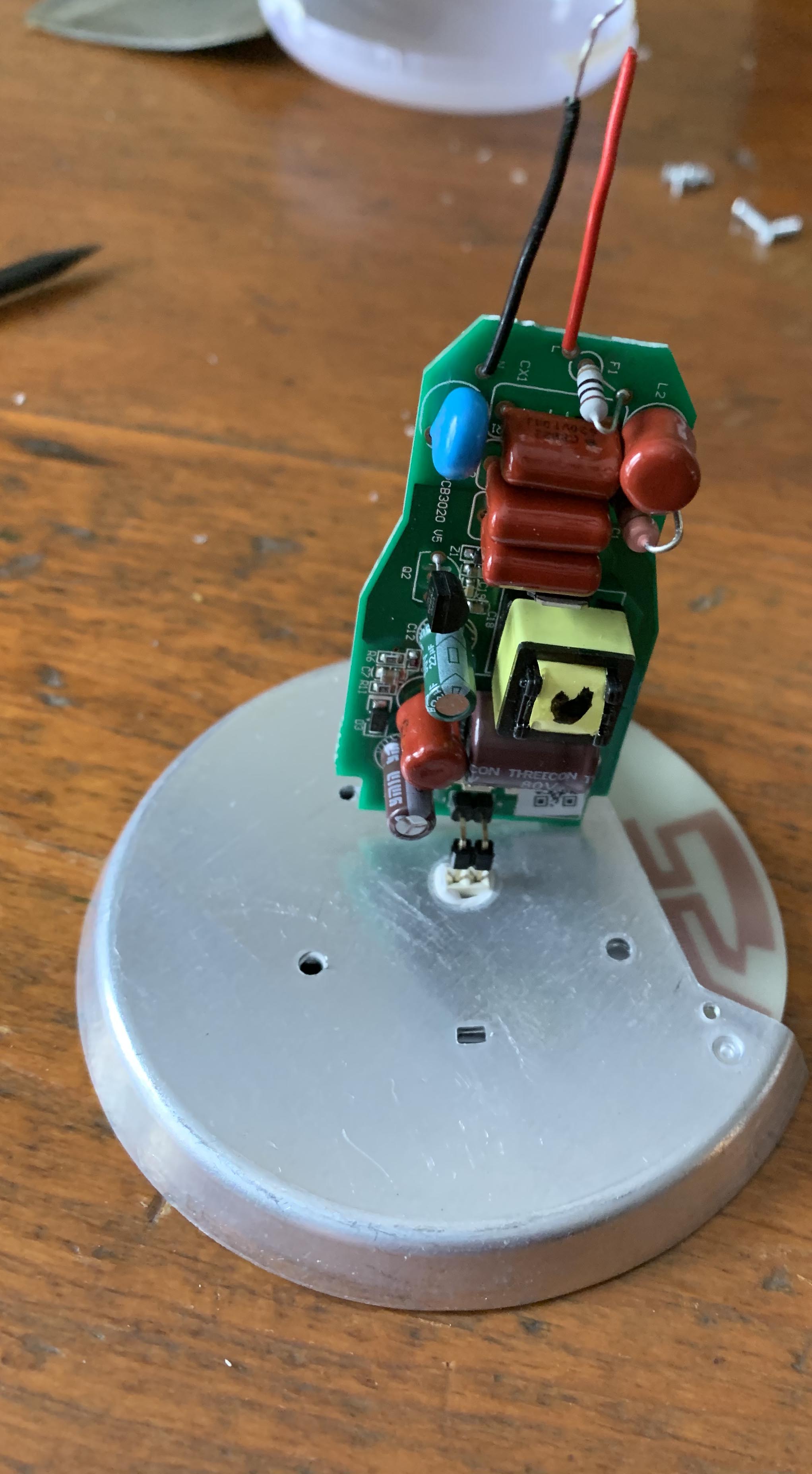
- The LED driver and Zigbee module simply unplug from the LEDs and heat sink. You can also attached wires to the module and the LED/heat sink assembly to create your own custom LED fixtures, allowing the LEDs to be mounted flat with ready made screw holes and supplied screws to hold them in place. If you're curious, the output voltage from the driver with the LEDs under load is 70v DC at 100%, and 62.3v DC at 1%.
It is also possible to skip the removal of the module from the driver board, and instead use it attached to the driver board with a 110v relay. AC relays work fine. However since the bulb was originally designed to fade to off, a mechanical relay attached to the driver output connections does not turn off instantly. If you don't need the device you're controlling to turn off instantly either, then this is a viable solution and less expensive to build.
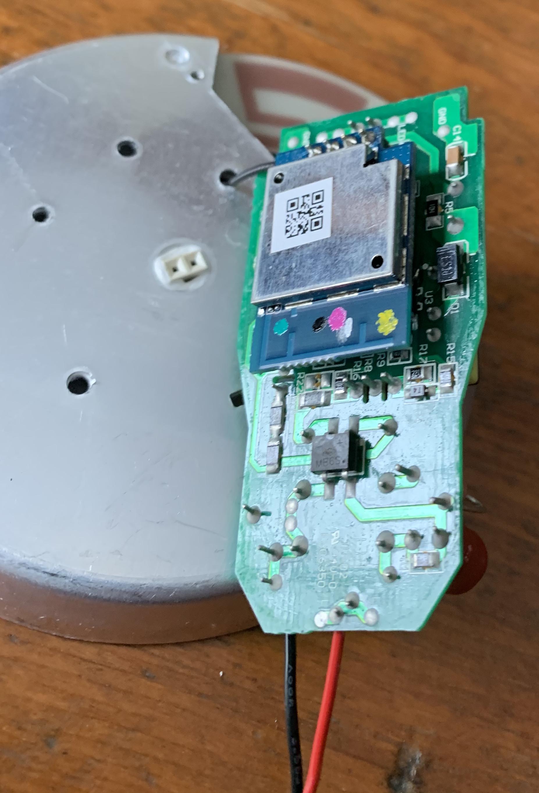
- The Zigbee HA module unplugs from the controller board by simply pulling it away. Use the flat end of your spudger to pry up at an angle on the antenna plug from where the wire is attached to it, separating it from the Zigbee module.
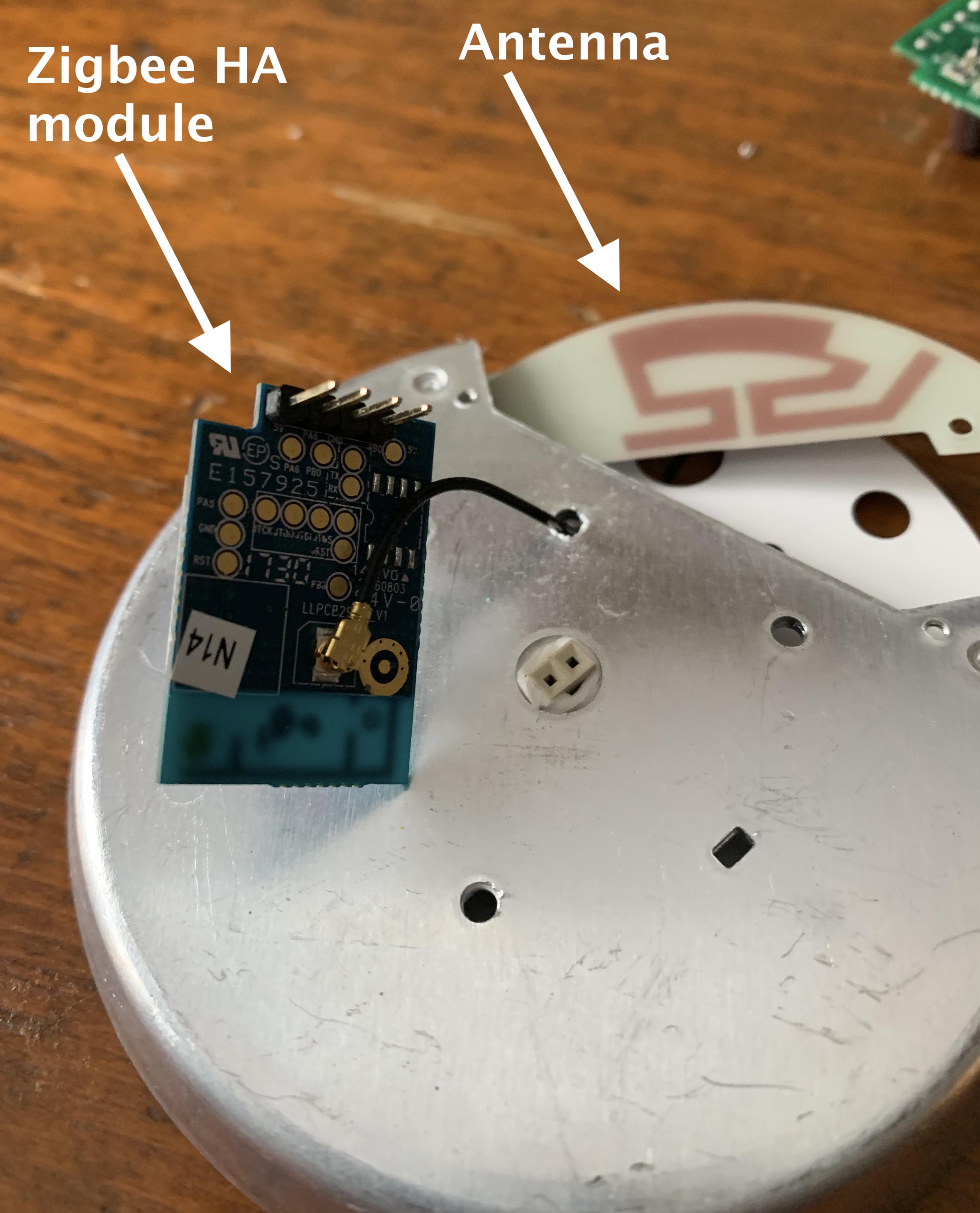
- The LED array is not glued to the heat sink. It lifts easily away, since once the screws were removed in step 5, the only thing left holding it in place is thermal paste. The paste is messy, but it's not caustic.
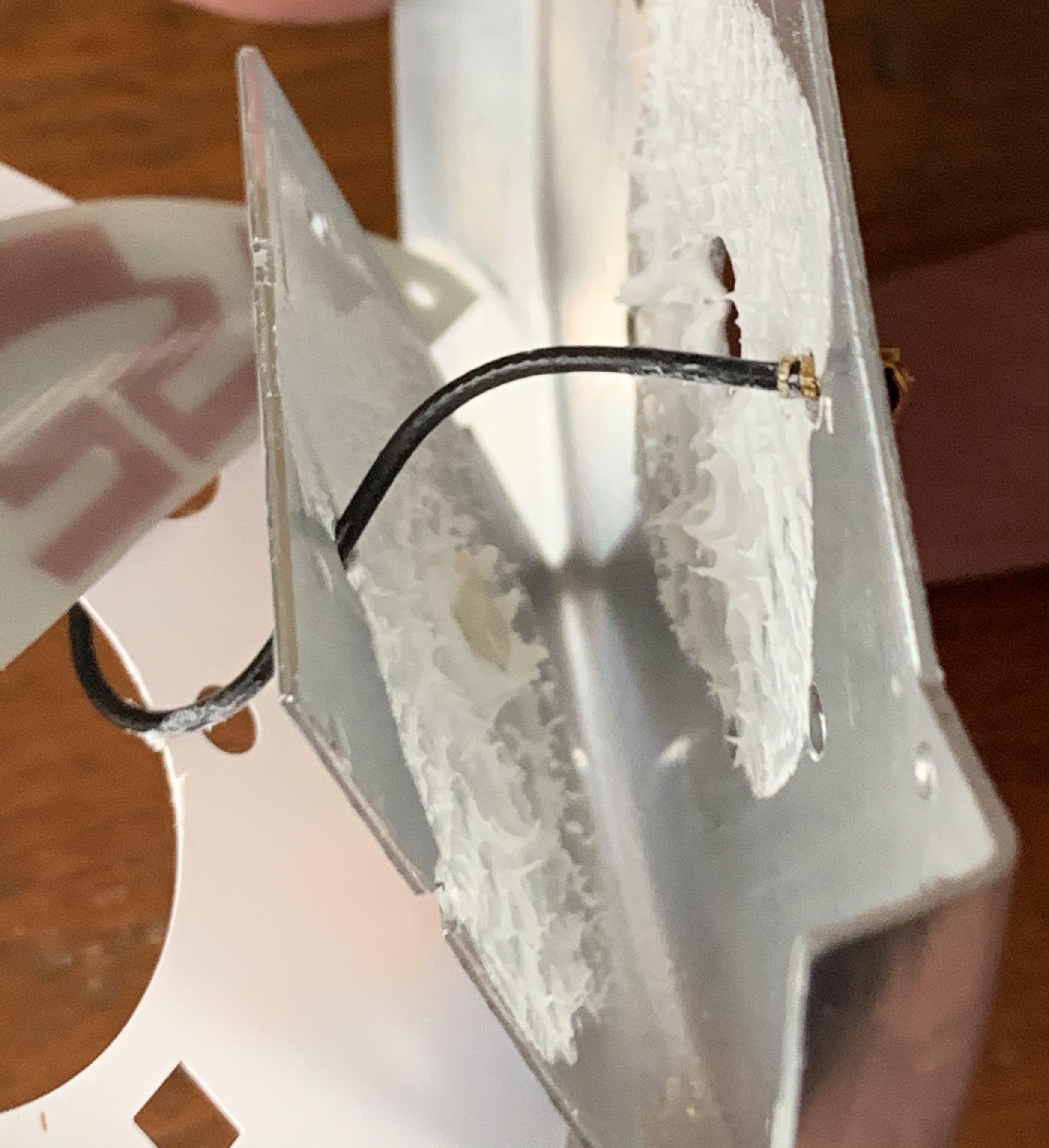
With the LED array detached from the heat sink, you can manipulate the antenna plug through the hole to remove it from the heat sink. It won't just easily pull out unfortunately, but I found that once I got it almost out, I could then just press firmly with the flat side of the spudger to force it through the hole without damaging it. However, you must separate the LED array from the heat sink, or the combined thickness will make it impossible to force the antenna plug through the hole.
Don't do this.  It worked once for me, but when I built the Switchmate project below and tried it again, I came close to causing permanent damaged the antenna connection. I now advise de-soldering the antenna wire from the antenna board, or if you are not going to reuse the LED heatsink, you can likely just use large diagonal cutters to carefully cut through the aluminum without damaging the antenna cable.
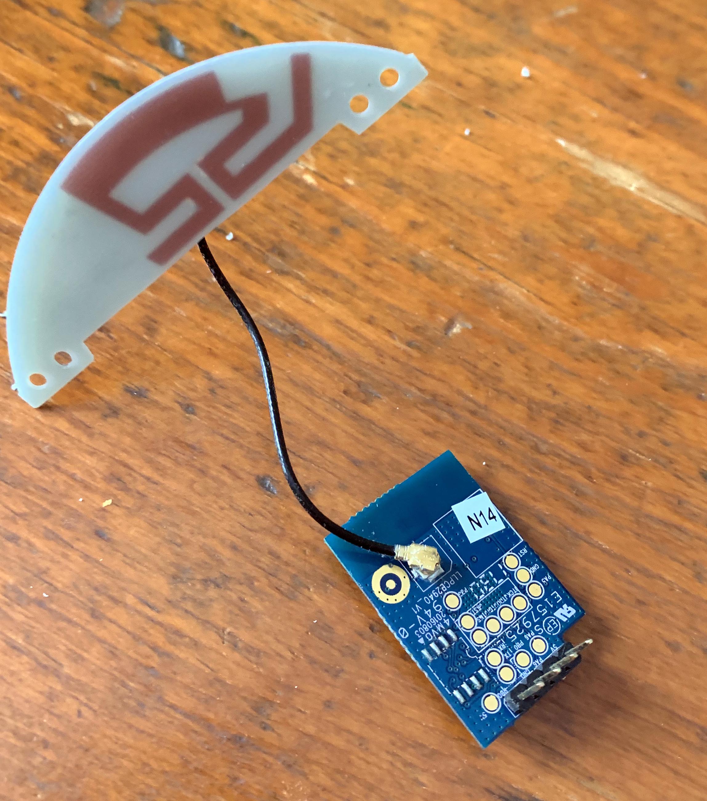
- Once the antenna is free from the heat sink, re-attach it to the Zigbee HA module. You will not be able to pair or control the Zigbee module if the antenna is not attached to it.
Zigbee HA module operation
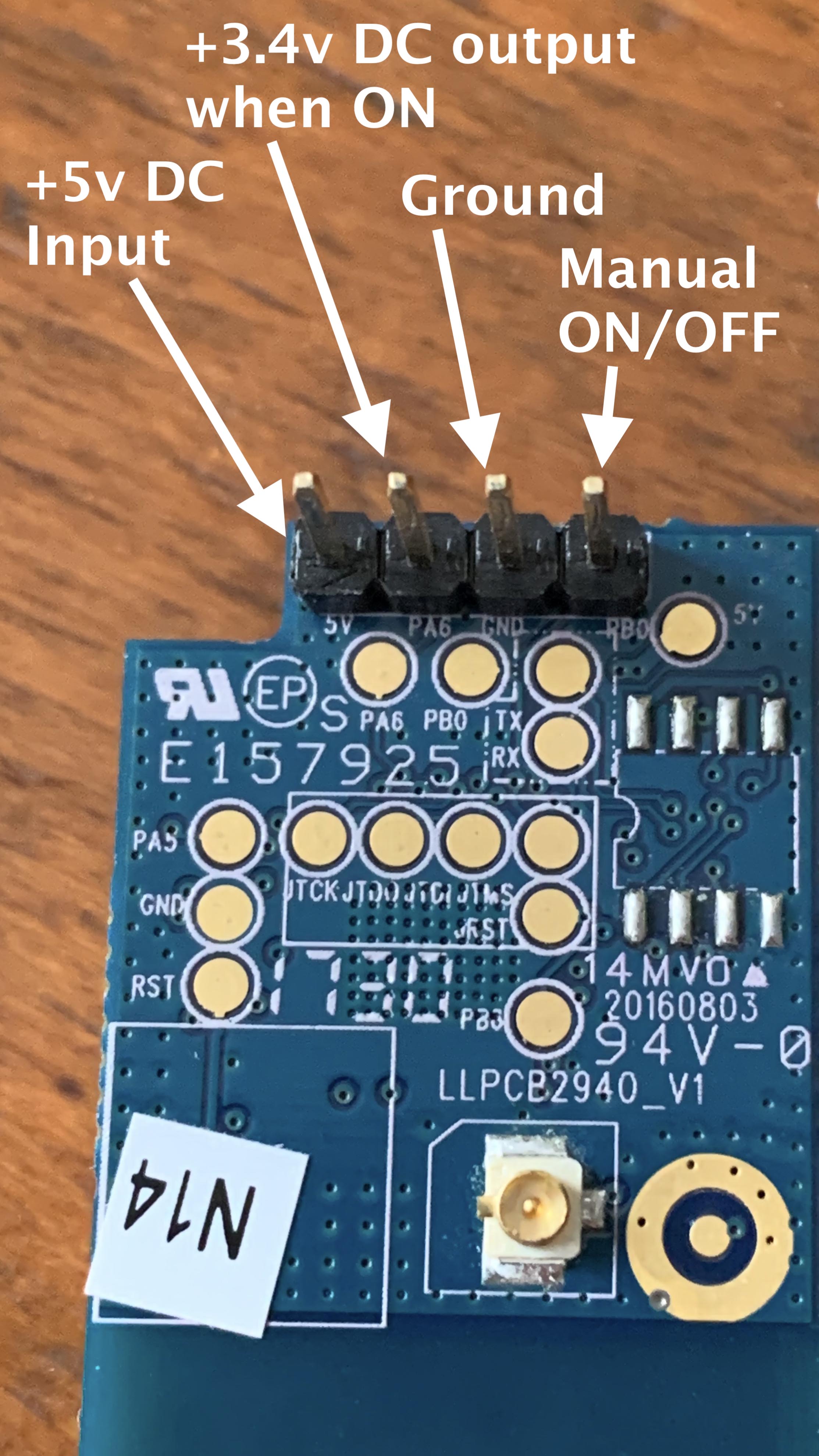
Here are the operational pins. These same pins are combined with the circuit ground connection and the reset test point to factory reset the module, and to pair.
From left to right:
5 volt input from your power supply.
The most logical choice is to cut off the micro USB end of a USB power cable, and supply power to the circuit by plugging the USB A connector into the power adapter. These cables seem to come with all kinds of devices today, and typically have just two wires in them, making the task very easy. Quite often I've found that these USB power cables have a RED insulated (+5v DC) and either a BLACK insulated or bare wire (negative or ground wire).
PA6
When the module is paired and turned ON either manually (as described here later) or via the Sengled bulb driver, Pin PA6 supplies 3.4v DC. When the module is OFF, there is no power on Pin PA6. This is a high level output, suitable to trigger a solid state relay, but is doesn't have enough current to drive a mechanical relay.
Ground
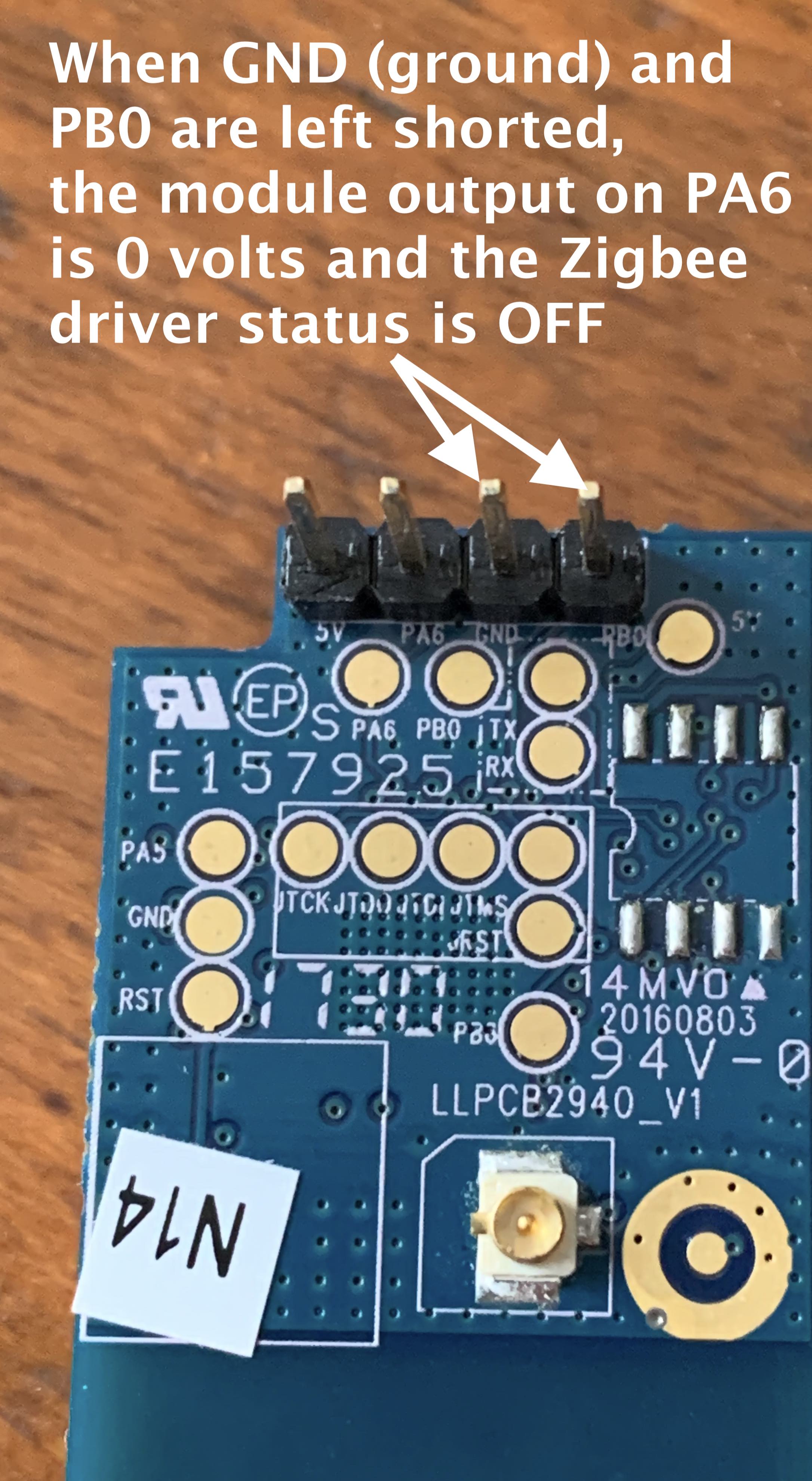
AKA the negative power terminal, but more accurately, it is ground. Ground is where the negative wire from your power supply goes, but when Pin PA6 is briefly shorted to ground following a factory reset, the module will enter pairing mode.
PB0
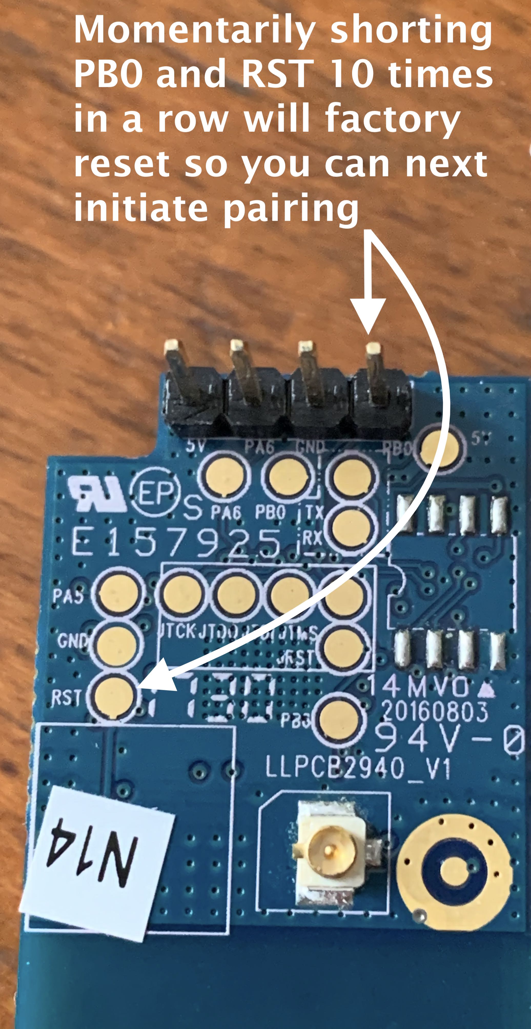
I was able to determine two uses for Pin PB0. The first as mentioned before is that it functions as a manual ON/OFF for the module output. So if the Pin PB0 is closed with the ground pin and held in that state, the module will stop supplying 3.4v DC to Pin PA6. If the connection between PB0 and ground is again opened, this overrides an OFF state that may have been sent from the driver. The module state will now be ON, and 3.4v DC is supplied to Pin PA6. Pin PB0 has a second important function, and that is when contacted briefly to the reset test-point on the Zigbee module 10 times in a row, the module will factory reset.
Zigbee module reset and pairing procedure
- Factory reset to prepare for entering pairing mode by shorting Pin PB0 with the reset test point on the board 10 times in a row. I could not just initiate pairing on the module. A factory reset was always required first.
- Initiate pairing (always AFTER a factory reset) by briefly shorting Pin PA6 to ground and then PA0 with the RST test point for 2 seconds (updated instruction). I would suggest that you DO NOT leave these pins shorted. It may have no ill effect, or it may damage the module. Remember that PA6, when the module is in the ON state will have 3.4v DC coming from it. I don't know what shorting it to ground for too long might do, but I'm guessing it won't be good. However, briefly is no problem. I tested removing and pairing the module many times in a row, and saw no issue from briefly shorting the connections.
Use
The module will pair with HE as a Sengled Element Classic bulb.
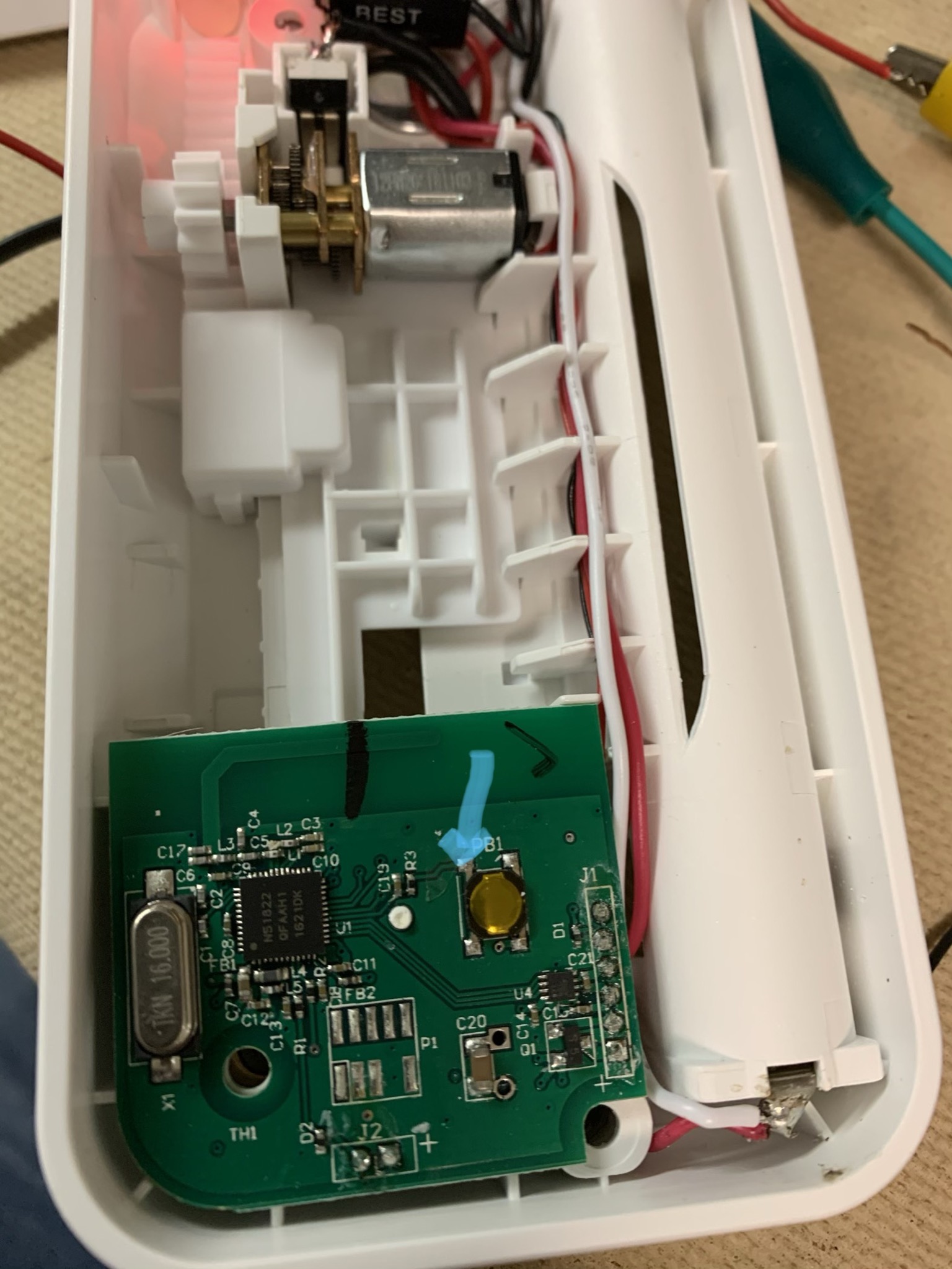
As mentioned from the beginning, the primary use I envision is triggering a solid state relay to close dry contacts. Another possible use is to convert a Bluetooth actuator such as the Switchmate devices. Of course, this would have to be powered by a 5v power adapter, because as I wrote before, the power drain from this module is 30mA. But this is a way to make your own actuators, which can do all sorts of things if you convert the linear motion of the Switchmate by using a lever in place of a light switch.
[UPDATE] See post below for complete instructions
I have a project in mind where I intend to convert two Switchmate devices into Zigbee, and then build an apparatus to press the lock and remote start buttons on an extra car remote, since my vehicle doesn't have the fancy Volvo API.
Another possible use is to convert a Switchmate to Zigbee, and then have that flip a high amperage 110-120v toggle. This would allow for reliable Zigbee ON/OFF control of large loads, without the 15 AMP limits or high cost of most switched outlets.
It's quite easy to have a two-stage relay setup. When the solid state relay engages, you could easily wire it so the 5v DC supply voltage for the Zigbee module will be sent to a 5v DC coil of a mechanical relay, giving you very high amperage contacts for use in a variety of applications.
Basic working schematic - example
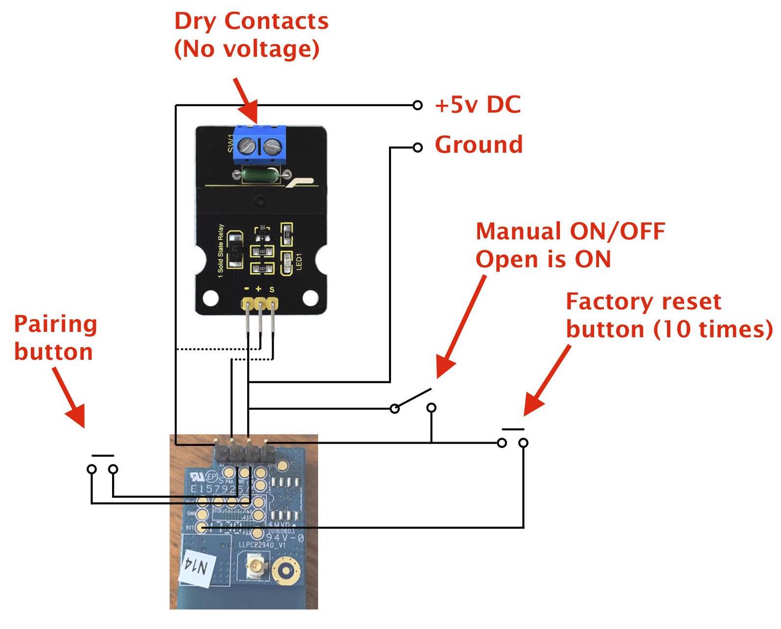
Solid State Relays
I have no reason to believe that the Zigbee module on its own cannot trigger a solid state relay that an Arduino can triiger, but full disclosure, I have not tested that yet. I have two solid state relay types on order, One is less expensive, but I don't like it as much because I will have to reverse ON and OFF. That lower cost solid state relay is OFF when the input voltage from the Zigbee module (3.4v) is high, which is the opposite of the Zigbee module ON/OFF state. The more expensive module is ON when the input voltage (3.4v) is high.
Update: I have now tested both solid state relay modules and I prefer the more expensive module because it doesn’t allow any voltage to pass through when it’s OFF. The less expensive module if, for example I pass 5v through it, when it’s OFF, it still passes 1.36v
Just for clarity as well, solid state relays pass a voltage, or do not pass a voltage. So in cases where you need fast response, but also need a no voltage contact, you will need to add a 5v relay to the output of the solid state relay. So when the input voltage from the Zigbee module is high, the solid state relay would pass 5v to a mechanical relay.
Let me know if you try this. With the cost of IKEA plugs being so low right now, I don't think this is a less expensive option. Even at my low cost of $3 CAD per bulb, and if I use a 110v mechanical relay with the original LED driver output, it still would be at least $9 per switch, and that's not an ideal switch either, because it's slow to turn off if I use with the LED driver as the power source.
Practicality
Where I think this might be a good project, and therefor worth the effort, would be customized lighting fixtures, multi-channel arrays, or situations where a high amperage load needs to be controlled. You can get controllers such as the Sinope 50 AMP load controller, and don't get me wrong, that's a good controller and it measures power consumption too. However, the Sinope controller is $100 USD ($133 CAD). Using this Zigbee module, a solid state relay, and a mechanical relay in combination, I can build a 30 amp controller for around $20 CAD. So having power measurement (which I personally already have with my Aeon HEMs), the $113 price difference does take some of the shine off the Sinope load controller.

 . Ended up with 5 Phillips Hue strips for $25 bucks each instead.