Furnace Zone Control using Virtual Thermostats with Cycling and Relays

I've embarked on a project that I thought others may be interested in, and I would be interested in some feedback.

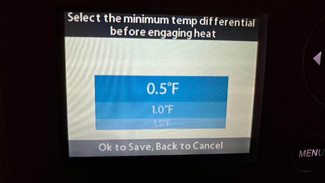
Unsatisfied with my Honeywell T6 Pro's ability to properly regulate temperature in some zones no matter what I set Cycles Per Hour to, I decided I would try my hand at coding a thermostat to control my heating zones.

To do this I had to disconnect my thermostat heating wires and instead use a ZigBee Relay board to control the zone valves from Hubitat.

This is the before-state wiring diagram for my furnace thermostats connected to the zone valves, and should be typical for most setups for hot water baseboard heating.

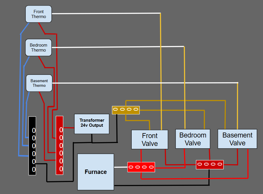
I disconnected the white heating wire from the zone valves and inserted relays in-between.

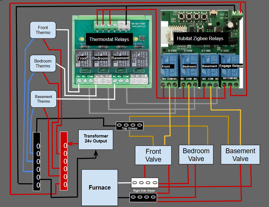
I added an extra board to automatically re-engage the thermostats, if I need to for any reason. This is controlled by the "engage relays" relay which allows me to switch between the ZigBee relay control or thermostat control remotely from a dashboard icon, or by pressing the button on the board. It is wired so the "all off" state uses thermostats. If Hubitat or a board goes down on a below zero day, I didn't want to be in the basement wiring the thermos back to the valves to get heat back.

The boards were each about $20 on Amazon, so with the bus rails I only have about $50 into this project.

Then came the harder part, writing a virtual thermostat driver to run the heat. Having baseboard heat, there is a large delay in the heat coming up and going down.

I started with a tight hysteresis, but I still went under setpoint waiting for heat, and over setpoint waiting for it to stop. It still was working better than the T6 thermostats alone.

After a discussion about T6 thermostats in another thread, I realized that I needed to add cycling to my driver, to turn the heat on before it goes below setpoint, and to turn it off before it reaches setpoint.

It was more difficult to code than I had anticipated. I could not find any good algorithms for a cycling thermostat, so I played around until I got something working.

Not mentioned yet, but to use a virtual device to control actual devices also requires a controller app that subscribes to events to sync temperature sensors and to turn the zone valve relays on and off with the thermostatOperatingState.

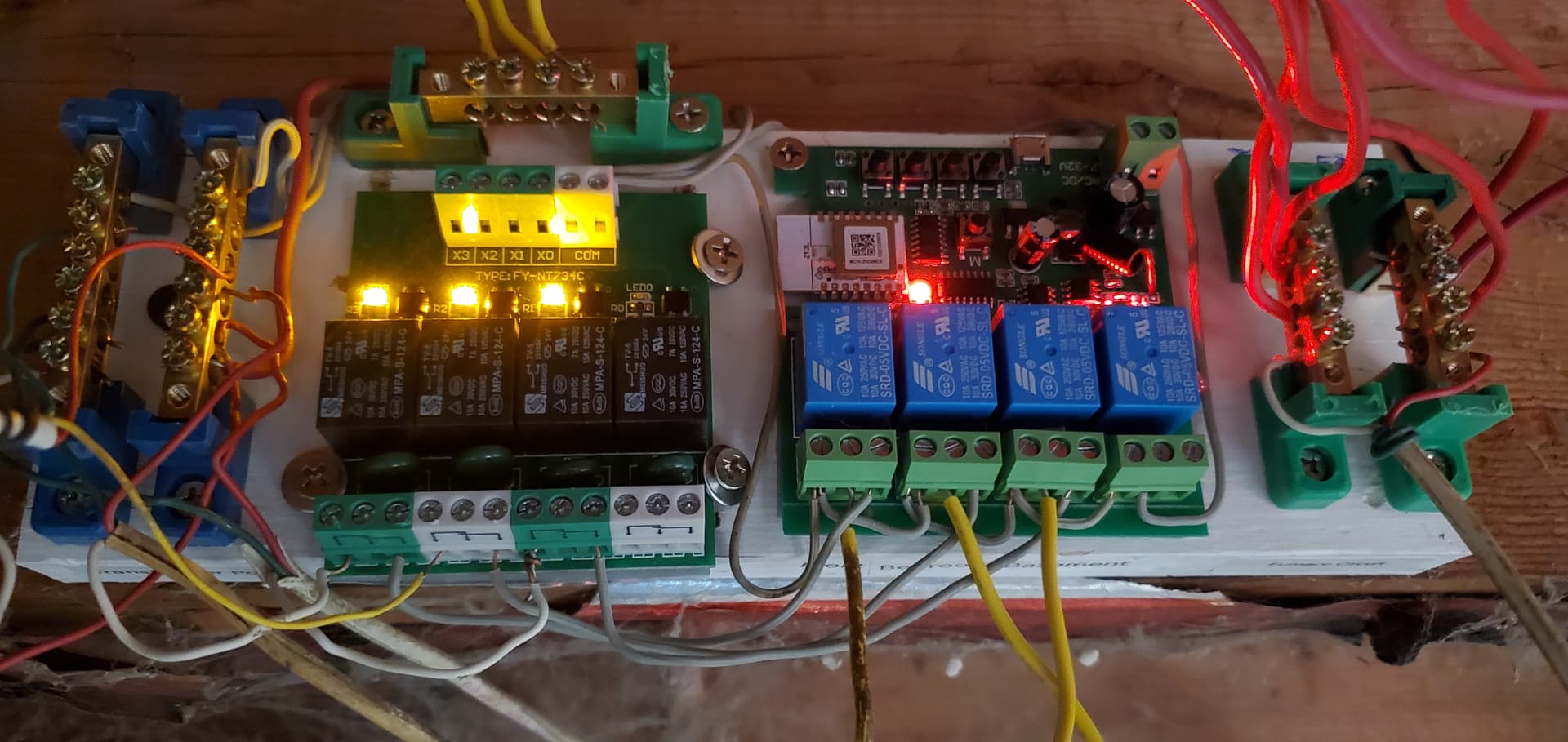
Here is picture of the boards wired:

My driver with cycling works like this:

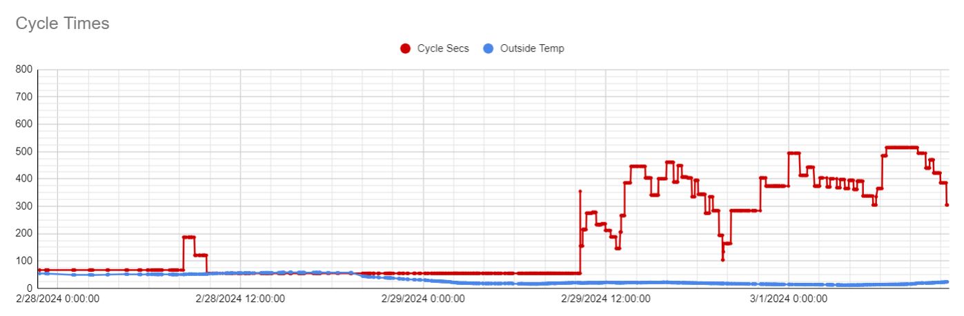
Choose a cycles per hour in preferences. This is used in cycleInit() to assign a cycling duration and a waiting interval, based on an outside temp of 32 degrees. I found the best calculation for this to be 15/cycles. You would think 30/cycles would be better, to get the proper on and off cycles per hour, but the cycles are way too long using this and there were fewer cycles than set. 15/cycles works pretty well as a starting point.

From there I also sync the outside temp to the driver using the controller app. A calculation is performed when out temp changes to add seconds to the cycles and subtract seconds from the wait interval, based on how much above or below freezing. I have been using about 10sec per degree for this, though I need some colder temps to really test it out. I left seconds per degree change as a preference so I can play with the value. Above freezing gives negative changes, so in that case cycles are shortened and waits are lengthened above freezing.

I use three hysteresis settings (maybe better to call them offsets)

  1. hysteresis - This determines when to Ramp. I use 0.2 degrees generally. So at 0.2 degrees below setpoint, the furnace will ramp continuously up to that temperature. Once at temp, cycles kick in to maintain temperature
  2. cyclingHysteresis - determines when the cycling starts above setpoint. Depends on the zone, but generally around 0.2 to start cycling when temp is 0.2 above setpoint. If a cycle is running and temp goes above this point, cycling will stop and there will be a wait set.
  3. stopHysteresis - This is the stop point for a cycle, and it is a bit less than the cycleHystereis. This will stop a cycle if temperature is rising, and the thermostat is cycling. If a cycle actually gets up to the cyclingHysteresis point before turning off, it tends to overheat, so the stop hysteresis stops the cycle a bit before that. It only stops with rising temp so it will not stop the cycle while running a cycle, since the heat is usually still trying to recover (the temp is still going down).

After each cycle, it enters a waiting period that stops a new cycle from starting. This is because the temperature from baseboard heat is so delayed that the temperature is still rising after a cycle, and a cycle will just start again without a wait as it is still within the start cycle range.

Once the wait expires, a cycle can start if temp is <= the cyclingHysteresis temperature.

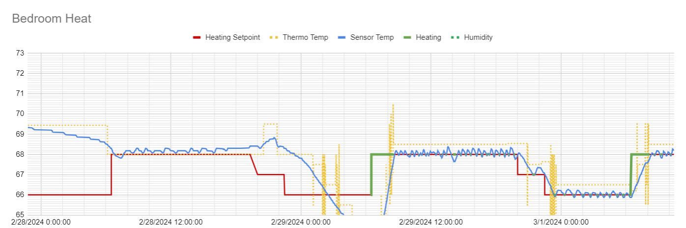
This has been working pretty well for the last few days. I am maintaining a temperature now within a 0.3 degrees swing.

Here is the driver in its current state:

https://raw.githubusercontent.com/cburges2/Hubitat/main/Drivers%20Code/Virtual%20Thermostat%20Cycles.groovy

It was a fun project, and I really got my heating under control. I encourage others to use a temp sensor with more accuracy to see what your thermostat temp swings really are.

I'm not sure what is up with the T6 Pro cycling, but there are not enough settings available to really tune it into my particular zone needs. I sync everything from the T6s to the virtual thermostats, so I still use them as usual to change setpoints, etc.

2 Likes

Those Honeywell thermostats seem to have complicated algorithms and while they may work well for some systems, for others they seem to make things worse.

I did a fancy controller for my gas fireplace. That thing takes a long time to start producing heat and keeps pumping it out for a while after it's been turned off. I had to code an anticipator which is sort of the opposite of hysteresis.

Using outdoor temperature as a reference is a good start. A house typically has a lot of thermal inertia (especially in the basement) so it may take some hours, days or weeks for the effect of outdoor temperature to become apparent to your heating system.

Yes, this basically amounts to an anticipator since the cycles start before temps are below setpoint, and a cycle can end before temp is back at setpoint. So with cycles I am anticipating the need for heat, as well as the need for it to shut off.

Good point on outside temperature. I was going to use temp change per cycle, or temp change per hour, to adjust cycle times. That would capture how long the zone keeps the thermal inertia (which is clearly longer in the basement, so just outside temp is not a good indicator of heat loss)

I went with outside temperature as an easy way to get something working, but I really should check how fast the zone is losing heat to make a more accurate adjustment.

I also saw that cycles heat a bit higher when the setpoint is lowered, which makes sense since shorter cycles are needed with less demand, so I am playing with a small adjustment to cycle time with setpoints as well.

My anticipator is geeked out and monitors the temperature rate of change and uses that slope to anticipate when setpoint hysteresis will be exceeded in both directions. This setup inherently adapts to outside temperature, what central heating is contributing and whether internal doors are open or closed. It works best if your thermometers give you frequent and precise updates. I had to do some complex smoothing to make it work for Zigbee thermometers.

I like that idea of using the slope to anticipate. Do you find rate of change to be linear? I was assuming it is probably a bit of a curve. Though I guess slope still works generally for a vary gradual curve.

For cycles, I can keep track of what my heat loss is when idle, and what my heat gain is when heating. From there I can calculate how long of cycle is needed to get to the target temp, and long of a wait is needed before we are back at the cycleOn temp. This would be feedback, not anticipation though. Each successive cycle would be adjusted based on the last cycle data.

That would also take into account the temperature setpoint and simplify things. Instead of tweaking cycle and wait times, the thermostat can just learn for itself how long of a cycle is needed.

I've found cycles per hour isn't something that needs to be set, it is going to be the result of how the zone heats and cools within the parameters I set for temp swings. So better to let the thermostat learn on its own how many cycles are needed.

I found that once I tweak the cycle times to what works, I am only at 1-2 cycles per hour, even with keeping the swing within .3 to .4 degrees, at temperatures close to 32 F.

The rate is surely not linear but treating it as if it is and updating it often seems to work well enough.

I'm not doing any intentional cycling, just turn it on when it predicts the room will get too cold and off when it predicts it will get too hot.

My implementation is optimized to get to setpoint ASAP when someone starts using the room and not overshoot setpoint while they're in there. Tightly maintaining a constant temperature is a lesser goal.

Thanks for sharing. Stuff like this is exactly why I got into home automation. Motion sensors and room lights are fine, but this project really highlights the problems you can solve with a little investment in time and effort.

My only suggestion would be to add some type of hard-wired temperature control (i.e. thermostat) to your largest/most-critical zone(s) and set it to some low-limit safety value. I would be concerned about some type of automation failure (hub lockup, etc.) happening while I was away for an extended period of time and having no heat.

That is a good point on the fail safe. Even though the unfinished basement where the furnace is does not get heated directly, it does maintain a certain temperature because of the heating pipes running around the ceiling. Maybe mount an old thermostat directly above the furnace...

Since I already have the disengage circuit, I would just need to remove power from the thermo relay board using the old thermostat and then the thermos would re-engage. I would need to open the circuit instead of closing it, but I could use the cool mode on the thermostat to open at the low (critical) temperature.

Then again, if I am leaving the house unattended, I can just turn off the engage thermos relay and leave it running by thermos. If I am not home, I don't really care if it is not maintaining a consistent temperature. Remembering to re-engage thermos before leaving would be the main thing.

1 Like

UPDATE:

So I have playing with this for a couple weeks now.

I tried calculating rise/fall rates and then calculating a cycle time, this really lacked the accuracy needed and just wasn't doable.

Instead, I started auto-adjusting the cycles. If a cycle goes over target temp, it is shortened. If it falls under target it temp, it is lengthened. This is based upon how much over and under target, and I make an adjustment based on how many tenths of a degree it was over or under.

This also required knowing the high and low of a cycle. This was a bit of an issue since there is bounce in most sensors, but by using two drops or two rises before calling it it a rise or a fall allowed me to find the actual high and low point of the cycles to make adjustments.

This fixed the issues with cycle times needing to adjust for several parameters.

  1. Changing outside temps
  2. Sun heating through the windows
  3. Cooking raising the room temp
  4. Room doors being closed (changes how the room with the temp sensor heats)

Here is the bedroom thermo graph:

I have the cycles pretty tight at this point, though there are a lot of checks in place to keep things from going astray. The first half of the graph was before self-adjusting was working, and I had introduced an exception at one point which stopped the heat from coming on at all for a bit before it was fixed.

I've also started adjusting the cycle hysteresis point based on the average of the high and lows, to keep the cycles on target to the setpoint. Depending on temperature outside, cycles will ride high in warm weather and low in colder weather, due to the time it takes to recover the temperature and how fast it falls.

Here is a graph of the cycle seconds for the bedroom being self-adjusted, once I got it working.

I expect to be tweaking this code for awhile still, and I need to finish applying cycles to cool mode, but I have a few months for that. In the summer, I run a split AC unit in the bedroom from the virtual thermostat, using a broadlink remote to send it the commands for cool and idle. Same with the front room with a window AC unit. Looking forward to a summer of very stable cooling temps.

It has still been a fun project, though at times frustrating. The code has become a bit sprawling as I keep adding checks for issues I see appear, but I will refactor it at some point to clean it up. I pushed the latest version to Github at the original link if interested.

I would just keep track of how frequently you're cycling your equipment. Depending on the device, time to failure can be more dependant on cumulative starts/stops than it is on total running time.

Aside from that, this looks very similar to a PID-type control used for standard on-off devices like resistance heaters. I have something like this on my electric smoker (overkill, I know). A cycle time is configured in the controller, 10 minutes for example. The controller output is stated in percent from 0 to 100. An output of 20% is converted into 2 minutes ON and 8 minutes OFF based on the cycle time. The controller looks at the actual temperature vs. the setpoint and adjusts the output accordingly. This type of system has some under/overshoot by necessity. Shortening the interval time reduces under/overshoot at the expense of increased cycles. Longer times reduce cycles but at the expense of greater temperature variation. The final determination on interval is a compromise of those two criteria. The LAG time between turning the end device ON and observing the effect (rising temperature) can also be a problem in these kinds of applications. Using the rate of change to predict and eliminate over/undershoot sounds easy, but can be very challenging.

Yes, I've thought a lot about the toll cycles can take on the equipment. My current gas furnace is now almost 20 years old, but the only failure I have had on it during this time is the igniter died a few years ago, which I was able to replace myself very easily and cheaply. I've also had zone valve heads die, but those are also easy to fix and cheap on Ebay as well. The minor lines on time axis in the chart are hours, so I'm still at 3-4 cycles when cold out, only one or two when around freezing.

So yes, I'm probably igniting more often, and moving zone valves more often. My equipment is getting old. However, with three zones calling for heat at different times, often the furnace is already heating another zone and does not need to ignite. There is also inefficiency and stress in the furnace coming up to temperature from cold, so I would think that with more frequent cycles, the furnace does not cool down as much, which is more efficient.

I do not use timed off intervals, other than a timed wait interval to give the temperature time to start rising so that another cycle does not start. Cycles start by temperature falling, and being below the cycle temperature, which is around just above or at setpoint. I set a scheduled job to stop the cycle after cycle seconds, then start the wait with another scheduled job to stop the wait. Usually a cycle ends while the temperature is still dropping. If the temperature does not recover, and it drops below the ramp point, the heat will come on to ramp back to temp, even if waiting. A shorter wait is set after a ramp, in case ramp was not enough to push temp over the setpoint, so another cycle can finish the job if temp starts dropping again before reaching setpoint.

1 Like

Just a final update and I will mark this solved.

I ended up calculating slope as temperature drops (heat) or rises (cool). I calculate every time a change big enough is detected, and I use that to calculate a cycle seconds value based on a coefficient set in preferences for the room. I keep a five-point running average of the slope values, and after each slope calculation I use the running average to calculate the cycle seconds.

This has been working well. Other changes are that heat or cool stops as soon as temperature starts rising. The timed cycle runs if temperature drops below the cycle point. After the timed cycle runs, it enters a wait period to see if temperature starts rising from the cycle. If not, a cycle will start again until the temperature starts rising. It will always continually ramp when below the ramping point.

Here is the current code for the thermostat driver:
Virtual Thermostat Cycles

Here is the companion app in current state:
Virtual T6 Thermostat Controller App

Warning: This code has not been cleaned up, so ignore the mess or any unused methods laying around, etc. I still have code commented out, and it is very heavy on the debug logging if turned on. I've tried to add initialization for anything that needs it, but I probably missed something, as I have not tried installing from scratch. However, they are currently working when set-up, and Ireally just posted here as a demonstration.