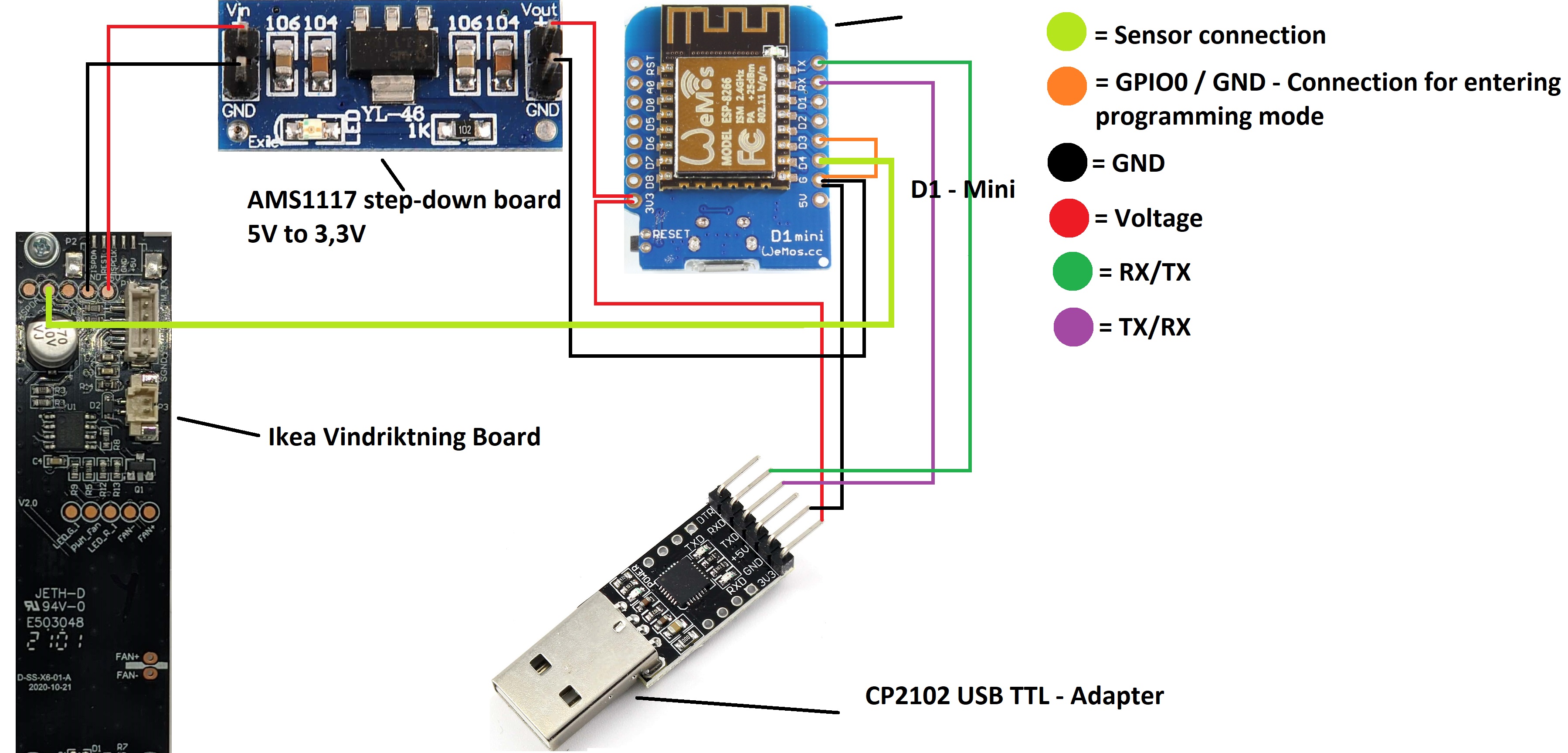
The parts are listed in the wiring. For everyone like me, who has no clue whatsoever about coding and that not everything is plug and play... DON'T FORGET TO GET THE DRIVER FOR THE USB TTL-ADAPTER!
I used the ones from silicon labs. They are open source and work like a charm.
Now, the things that helped me allot during my first attempt of getting into Tasmota:
Using Dupont-Wires. Having the possibility to easily connect and reconnect things is just wonderful, especially when some parts don't have or need to be connected all the time, like the D1 and the USB-TTL and the GPIO0 and GND. Soldering at least those pins with Dupont-wires was the best decision I've made. In fact, I used Dupont wires for all connections I've soldered, just to have the possibility to reconnect everything later on, if I want. Would JST-connectors have been the better option? Maybe, but that was, what I had on hand so.... leave me alone.
Pre-counting the connections and cutting my wires accordingly. Makes just everything easier. I've learned it the hard way...
Next, the things I've messed up.
Too many wires: I thought I would be such a smart boy, soldering a few extra wires to the different pins, so I can connect a few more sensors and perhaps a display. Yeah... Don't do that. The case of the Ikea Vindriktning might be big, but not that big... I've managed to cram everything in, but next time I would wait, till I have the parts and maybe 3D print a new case for my needs and all those smart things people do, who plan ahead.
Check your connections: After I've finally flashed everything successfully, and was staring at my setup-page of my new little baby, I was very disappointed that there was absolutely no read-out! Not even a negative read-out like: Sensor 1: No value!
Nope, nothing, until I realized, I should have connected the sensor to the Ikea - Board. And Bobs' your uncle, there we go, we got some nice values. Always check those things! I've learned it now.
Some last thoughts:
Was every part necessary? Following the different posts about the D1-Mini you can read, that it can be connected to 5V directly without an issue. Heck, you even git a pin for 5V. Reading the manufactures' instruction, it says to use always 3.3V. So I used the Step-Down module. Did I really need it? Maybe... Maybe not... I don't know. My thoughts on this: In case of doubt, it is always better to be safe than sorry.
Am I going to make more stuff now? Yeah!
I hope, that you enjoyed this little post and for everyone just starting out with Tasmota, always have one thing in mind:
I have no idea about coding, and I'm an absolute dumdum at this stuff. So if I can do it, you can do it.
I did that because of the manual of the board I bought. It stated to always use 3.3V. This was my first Tasmota project and I wanted to be extra sure. Looking at it afterwards, it wasn't necessary at all, but better to be safe than sorry.
Update: Thanks to the Tasmota Sync Driver from @garyjmilne, I had a breeze getting the Ikea Vindriktning into my Hubitat and start writing rules with it. I'm looking forward to the new drivers and building my own multisensor.
Got some D1 mini's yesterday with the headers on that were a breeze to flash. Got an Elgoo 37 sensor kit coming on Thursday. Now I don't want to go away on vacation next week!
Sure... that works.... Get the air sensor driver working first so I can use mine!!!! LOL. Just from the conversation in the forums, they seemed like decent folk.
Those look nice. I'm still trying to get my radar module up and running. Right now, I don't get, what I did wrong, because I've wired everything as I was supposed to. I have to check on the weekend. I'll also play around with my weight sensor. When I got it working, as it should, I'll send you the data to work with.
Very disappointed in this set. A few good sensors but most of them are analog so you can only have one attached and you have to calibrate the reading to turn it into something meaningful. I don’t think that is going to be trustworthy.
It’s going back.

 DON'T FORGET TO GET THE DRIVER FOR THE USB TTL-ADAPTER!


