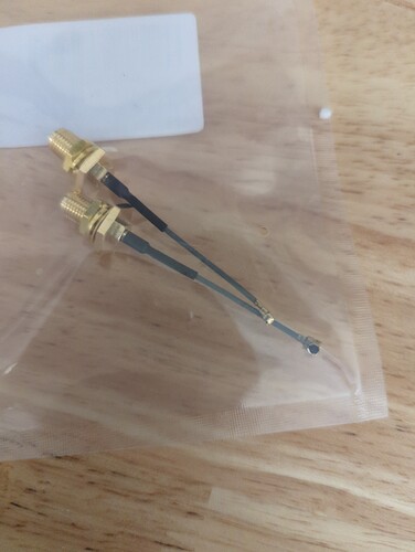
So, did you get the antennas installed?
A couple questions on Z-wave behavior, AAI, (after antenna installation), most of my contact sensors are the Ring V2 which initially connect at 100 Kbs then a few of them drop back to 40 Kbs. even though they are right next to a Aeotec 700 series repeater. I've also seen, on a few, that when I exclude and re-include they go back and stay at 100 Kbs. Is this the only way to force the device to 100kbs or should I just let the network figure it out over time?
This would be my suggestion. Post-modification, of my 26 z-wave+ devices, 25 now connect at 100 kbps; whereas initially less than half that number did.
The one that still connects at 40 kbps is a GoControl thermostat. The signal strength is terrific (38 dB), and the response time is ~100-150 ms, which is plenty fast for a thermostat, so I'm not going to mess with it.
Of my 31 z-wave devices, 30 connect at 40 kbps, many of which have RTTs of < 5 ms. So I am loathe to replace any of them.
Would it be possible to cut into the wire leading to the internal antenna and splicing in a connector for an external antenna so as to avoid having to desolder/solder on the Hubitat circuit board?
I imagine this would actually be far more difficult than a desolder/solder.
Yes. 
Things went in the dumpster overnight. Went from 34 Direct to 29, 5 more 9.6.
I checked the continuity of my joints, all seemed ok.
I could have a crappy antenna so I changed the 900 with a spare 2.4 I had just to see what happens.
I am considering doing this mod but couldn't these be used instead to make things easier?
Yes, just make sure if you use that sma pigtail, use an sma antenna. They are different from the ones I linked. And I wouldn't necessarily say it's easier. You still have to remove the old antennas, clean the solder, and reapply with the same skill. Differences being there are only two joints to solder, and if you mess up it costs you $7 per attempt vs 30 cents.
Also those are really long. The thinner ones are ok if longer but those thicker wired ones you really want to keep them as strait as possible.
Make sure the nuts are really tight on the lid or you could rip off the traces if it rotates.
Makes sense yeah it doesn't look like you need more than an inch of wire. I just saw the solder on ones instead of soldering on the little connector. Just trying to figure out if one is going to give better performance. The plug ones I feel would be better performance because there is less solder and less wire that isn't inside the coax shielding...
Make sure it's long enough to maneuver the cover back on ! or you'll be really pissed
LOL yeah I feel like this is like most connections you want the wire shortest possible and not exposed outside the coax shielding which is why I was thinking to do what you did. I have been trying to decide if I want to try to reuse some pieces from things I have taken apart that broke and de-solder the little connectors that go on the boards from an old WLAN card or just order new...
I used to have an ATT Digital Life system and I took it apart, found there are a bunch of connectors and a couple antennas. There are 900mhz antennas for communicating with the proprietary 915mhz transceiver says the fcc documentation. Just wondering if I reuse that antenna or get a new one that I know what the specs are for certain. I guess I could try and see what happens...
The little u.fl connectors are cheap enough, and are delicate. I would just order new ones.
Good call, easier to work with too.
If they were ceramic or something I'd say go for it, but they are some kind of plastic.
Yeah or if they cost a lot of money, I am also guessing the ones that are on a wlan card might not be the same for soldering on since it was placed on there by a robot. I am excited to try this and see if I get the zwave to be more than 40kbps.
Keep in mind that the antenna connector will be attached on the top half of the case, whereas the board is attached to the bottom half. You need some room to maneuver the case back together without popping the u.fl connection. 8-10 cm (3-4 inch) works well.
Yea it helps to mount the pigtail to the lid and then connect it to the u.fl connector, that way you can lay the board on the lid with just an inch or so lifted off to fit your finger in to mush on the connector. It will want to go on crooked with the side pointed towards the wire wanting to go on first so favor the downward pressure towards the other side of the connector.
It's hard to describe but you'll know what I mean after you do it once. You should feel a satisfying click if it goes on correctly.
LOL yeah I have dealt with these little plugs many times with other equipment just haven't done the soldering on of the ports.


