This is a post on my solution for integrating my swamp cooler into my Hubitat automated home.
Anyone who lives in the dry southwest US (I'm in NM) knows about swamp coolers, or evaporative coolers. If you are one of those people, you can skip the next paragraph.
Evaporative coolers are a big box that has a fan that sucks outside air through a pad or multiple pads that is(are) soaked by water pumped up out of a dependent reservoir to the top of the pad(s). The water that reaches the bottom of the pad(s) drips back into the reservoir for recirculation. The air passing through the wet mat causes evaporation and due to the latent heat of evaporation of water absorbed in the process - results in both humidification of the air and cooling. The air is then pushed into the house for cooling. windows in the house have to be cracked to allow air to escape and to promote circulation of the cooled air. There are two motors which are controlled to turn them on - 1) the water pump, and 2) the fan motor which often has two speeds, but sometimes only one. In NM most modern homes have the swamp cooler integrated with forced air ducting for distribution of the cooled air to the home, but not always.
Evaporative coolers always have their own controllers which control the relays to switch on/off the motors. These are often set up in series with a traditional thermostat which does the job of sensing internal home temperature and determining if the cooling apparatus needs to be triggered on. But the thermostat does not send any signal to the swamp cooler controller about whether to use high or low fan speed and doesn't turn on the water pump for a minute or two before the fan to pre-moisten the pads (this results in drawing in hot outside air for a few seconds before the pads are wet). Usually these settings are "manually" set on the swamp cooler controller and then when the thermostat turns cooling on - you get what has been set, and only that until someone changes those settings. A Hubitat integrated swamp cooler controller would allow some automation of those settings...
Some homes (like mine) have BOTH refrigerated air and swamp coolers. My swamp cooler is on the roof over my sun-room and does not integrate with my forced-air ductwork, but instead just dumps moist cooled air into the sun-room. I Like to open the door from my sun-room to the rest of the house and allow higher humidity cool air to mix with the dry refrigerated air, etc. But until now I had no way to incorporate control of my swamp cooler with the rest of the system - i thought it would be nice to use environmental sensors in the house to check humidity levels and adjust the ratio of swamp cooler cooling to air-conditioner cooling, etc.
So my solution is a bit of a kluge (but it works nicely) with the following components:
one (1) Z-Uno board -- [$69.90]
https://z-uno.z-wave.me/
https://z-uno.us/?product=zuno
one 4-relay 5-v break-out board [$9.99]-- https://www.sainsmart.com/products/4-channel-5v-relay-module?variant=45099713556&msclkid=b74ef0c980eb19a71f269011538ff1f7&utm_source=bing&utm_medium=cpc&utm_campaign=Shopping&utm_term=4575617643108710&utm_content=SainSmart%20Catalog
one AC DC Converter Module Universal 110V 120V 220V 230V to DC 5V 12V Isolated Switching Power Supply Board (DC 5V 2A Version) [$11.50] -- https://www.amazon.com/gp/product/B07SGQ6XXR/ref=ppx_yo_dt_b_asin_title_o04_s00?ie=UTF8&psc=1
a small piece of bread-board to mount the Z-Uno - something like this would work: https://www.amazon.com/Gikfun-Solder-able-Breadboard-Plated-Arduino/dp/B071R3BFNL/ref=sr_1_5?dchild=1&keywords=breadboard+pack+solderable&qid=1624823592&s=electronics&sr=1-5
Some headers for connecting the wires (optional - as you could just solder connections to the breadboard) - this would be a nice set to get started with -- https://www.amazon.com/Glarks-Connector-Assortment-Stackable-Breakaway/dp/B07CWSXY7P/ref=sr_1_3?dchild=1&keywords=breadboard+headers&qid=1624823707&s=electronics&sr=1-3
some wires
An old micro-USB cable to sacrifice for the project
a soldering iron, solder, electrical tape, multimeter, etc.
I then chose to get an expanding outlet/switch cover from Lowes to put this thing in the wall where the old swamp cooler controller was removed. -- https://www.lowes.com/pd/TayMac-1-Gang-Rectangle-Plastic-Weatherproof-Electrical-Box-Cover/3772757
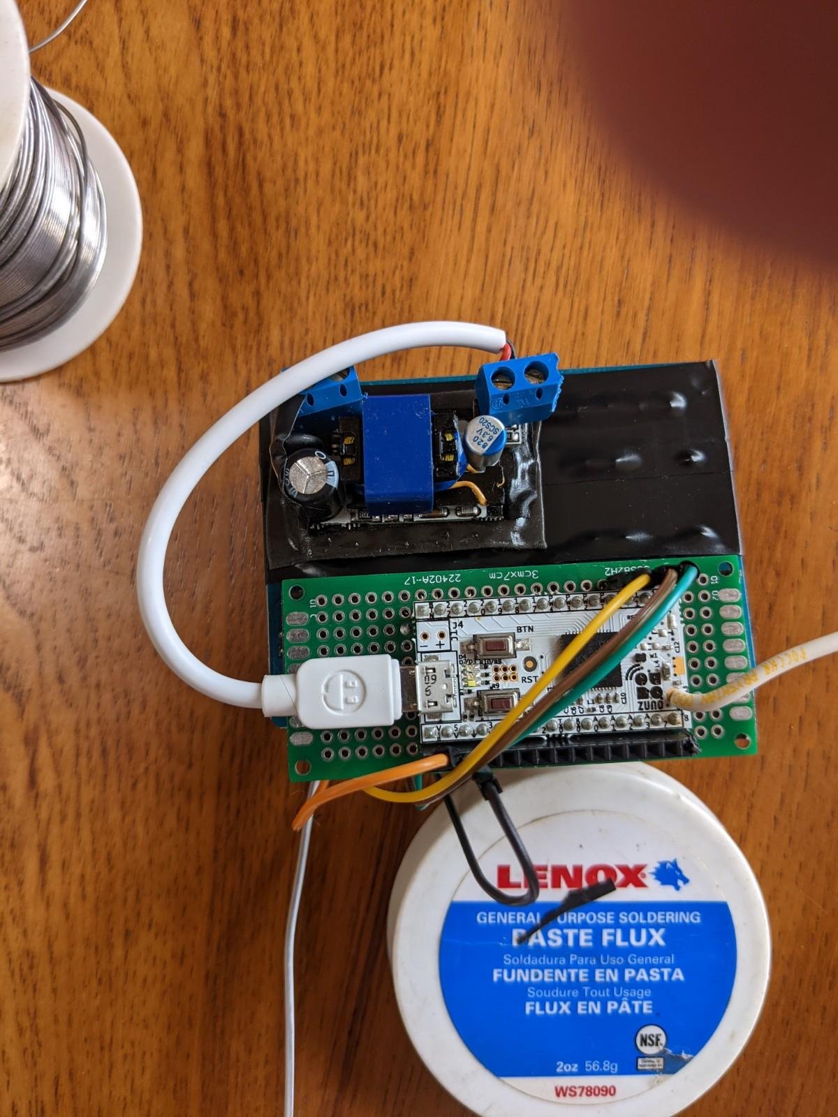
So to make the controller, I first soldered the Z-Uno to the breadboard piece I had laying around.
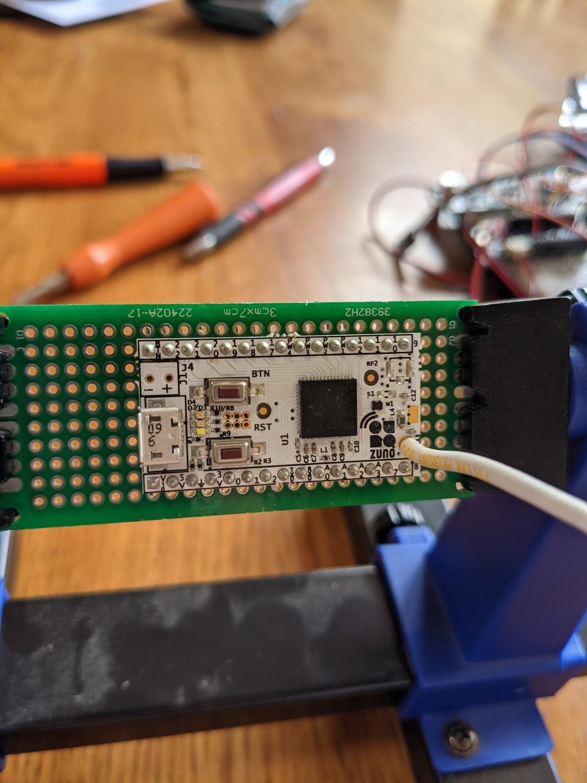
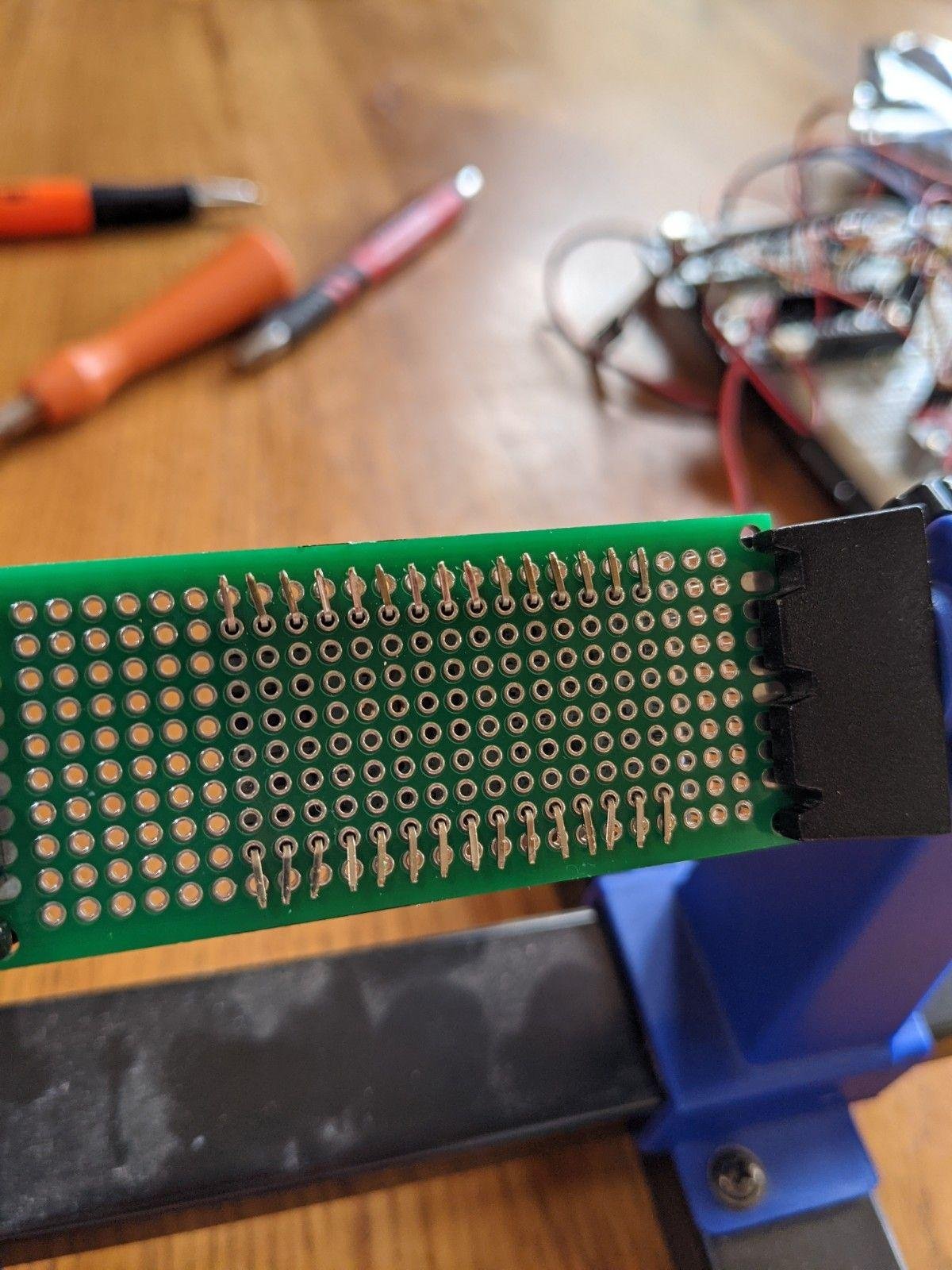
Header strips were on the breadboard to simplify wiring (see pictures below).
Then an old micro-USB cable was chopped up and I determined which wires were the power and ground and connected it to the AC-DC(5V 2A) converter module. Alternatively, you could power your Z-Uno from a standard plug-in USB charger (they are ubiquitous these days) and a USB-to-USB-micro cable. I wanted something I could potentially put in an outlet gang box so I used the small module for the board's power source. I soldered screw terminals to the converter module, but you could just solder the USB cable to the module itself.
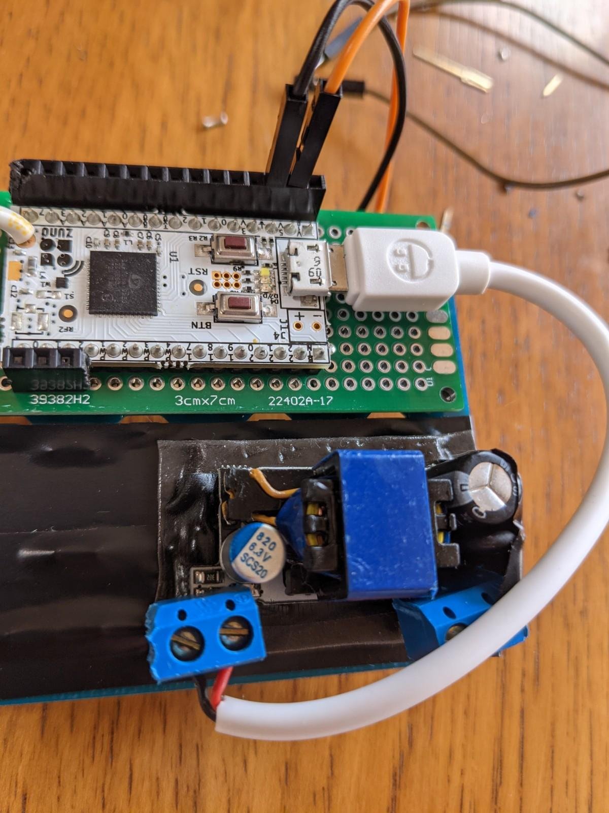
Next, the relay break-out board and the bread-board and power module were taped up with rubber electrical tape so I could stack components for compactness.
The Z-Uno allows integration into your Z-wave Plus network (see their website - link above), but you program its functions like an Arduino. If you don't know what an Arduino is just google it. You will need do download the Arduino IDE software to a computer to program the Z-Uno and follow the process of getting the Z-Uno libraries installed into the IDE in the Z-Uno website's "getting started" section. (this is a mandatory step)
My Arduino code for the Z-Uno allows one to add the Z-Uno to Hubitat's Z-wave network and in Hubitat, declare it as a "Generic Z-wave Dimmer." I registered the Z-Uno to my Z-wave network and first uploaded some of the sample scripts to it to "play around." Eventually I uploaded my swamp-cooler controller code...
My Arduino code for uploading to the Z-Uno device follows:
 /* This is an Evaporative Cooler Controller sketch
 * that uses the z-wave Multilevel Switch (Dimmer) protocol
 * It flashes the built in LED once then off 1 sec for setting one (pump only)
 * It flashes the built in LED twice then off 1 sec for setting two (pump and low fan)
 * It flashes the built in LED 3 x then off 1 sec for setting three (pump and high fan)
 * It flashes the built in LED 4 x then off 1 sec for setting four (low fan only)
 * It flashes the built in LED 5 x then off 1 sec for setting four (high fan only)
 */

// LED pin number
#define LED_PIN 13
// pin number, where relay is connected
#define Pump_RELAY_PIN 9
#define FanLow_RELAY_PIN 10
#define FanHigh_RELAY_PIN 11

// variables to store current and last dimmer value sent by z-wave controller
byte lastSetDimmer;
int intSetting;

// 0 for off
// 10-20 for setting one
// 30-40 for setting two
// 50-60 for setting three
// 70-80 for setting four
// 90-100 for setting five

// next macro sets up the Z-Uno channels
// in this example we set up 1 switch multilevel channel
// you can read more on http://z-uno.z-wave.me/Reference/ZUNO_SWITCH_MULTILEVEL/
ZUNO_SETUP_CHANNELS(ZUNO_SWITCH_MULTILEVEL(getter, setter));

void setup() {
  pinMode(LED_PIN, OUTPUT); //set up LED pin as output
  pinMode(Pump_RELAY_PIN, OUTPUT); // set up relay pins as output
  pinMode(FanLow_RELAY_PIN, OUTPUT); // set up relay pins as output
  pinMode(FanHigh_RELAY_PIN, OUTPUT); // set up relay pins as output
  // relay control output pins are set to HIGH as the Z-Uno boots up because pulling them LOW
  // turns on the associated relay on the break-out board
  digitalWrite(Pump_RELAY_PIN, HIGH);
  digitalWrite(FanLow_RELAY_PIN, HIGH);
  digitalWrite(FanHigh_RELAY_PIN, HIGH);

}
void loop() {
   for (int i = 0; i < intSetting; i++) {
      analogWrite(LED_PIN, 255);
      delay(200);
      analogWrite(LED_PIN, 0);
      delay(200);
   }
delay(1000);
}

// setter function is called once a command comes
// from the Z-Wave controller or over controlling device
void setter(byte value) {

  // value is a variable, holding a "new value"
  // which came from the controller or other Z-Wave device
  if (value > 10 && value <= 20) {
    //signal received for setting 1
    intSetting = 1;
    digitalWrite(Pump_RELAY_PIN, LOW);//turn relay on
    digitalWrite(FanLow_RELAY_PIN, HIGH);
    digitalWrite(FanHigh_RELAY_PIN, HIGH);
  }
  else if (value > 30 && value <= 40) {
    //signal received for setting 2
    intSetting = 2;
    digitalWrite(Pump_RELAY_PIN, LOW);
    digitalWrite(FanLow_RELAY_PIN, LOW);
    digitalWrite(FanHigh_RELAY_PIN, HIGH);
  }
  else if (value > 50 && value <= 60) {
    //signal received for setting 3
    intSetting = 3;
    digitalWrite(Pump_RELAY_PIN, LOW);
    digitalWrite(FanHigh_RELAY_PIN, LOW);
    digitalWrite(FanLow_RELAY_PIN, HIGH);
  }
  else if (value > 70 && value <= 80) {
    //signal received for setting 4
    intSetting = 4;
    digitalWrite(Pump_RELAY_PIN, HIGH);
    digitalWrite(FanLow_RELAY_PIN, LOW);
    digitalWrite(FanHigh_RELAY_PIN, HIGH);
  }
  else if (value > 90 && value <= 100) {
    //signal received for setting 5
    intSetting = 5;
    digitalWrite(Pump_RELAY_PIN, HIGH);
    digitalWrite(FanLow_RELAY_PIN, HIGH);
    digitalWrite(FanHigh_RELAY_PIN, LOW);
  }
  else if (value == 0) {
    //signal received to turn all off
    intSetting = 0;
    digitalWrite(Pump_RELAY_PIN, HIGH);
    digitalWrite(FanLow_RELAY_PIN, HIGH);
    digitalWrite(FanHigh_RELAY_PIN, HIGH);
  }

  // let's save our value for the situation, when the controller will ask us about it
  lastSetDimmer = value;
}

// getter function is called once the controller
// or other device in the network asks Z-Uno about
// it's current level
byte getter(void) {
  return lastSetDimmer;
}
Now, all you have to do is wire things up!
The AC-DC converter module does connect to your home's main AC power in an outlet box (the way I did it), so flip-OFF your breaker switch to the swamp cooler controller in you home's breaker box!!!
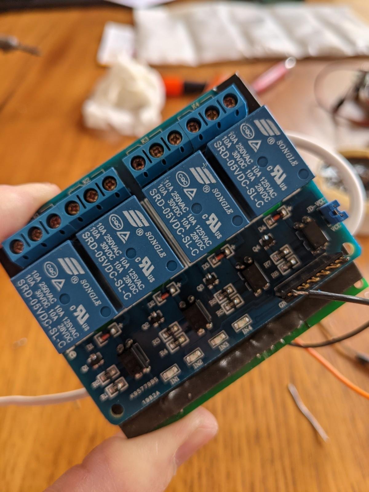
You have to figure out which wires going to/from your old swamp-cooler controller do what. Usually there is a guide on how to wire the old controller on the outide of the back of it. It doesn't matter which relays you use on the break-out board for what as long as the relay controlled by pin 9 off the Z-Uno controls the water pump, pin 10 controls the relay for fan LOW, and pin 11 controls the relay for fan HIGH, (the way I wrote the arduino script).
You also have to run 5V and ground from the Z-Uno to the relay break-out board. All of this is shown in one of the pictures above.
This picture shows the power converter wired to the main AC power at the wall and all the swamp cooler wires wired to the relays I used (only 3 of the 4):
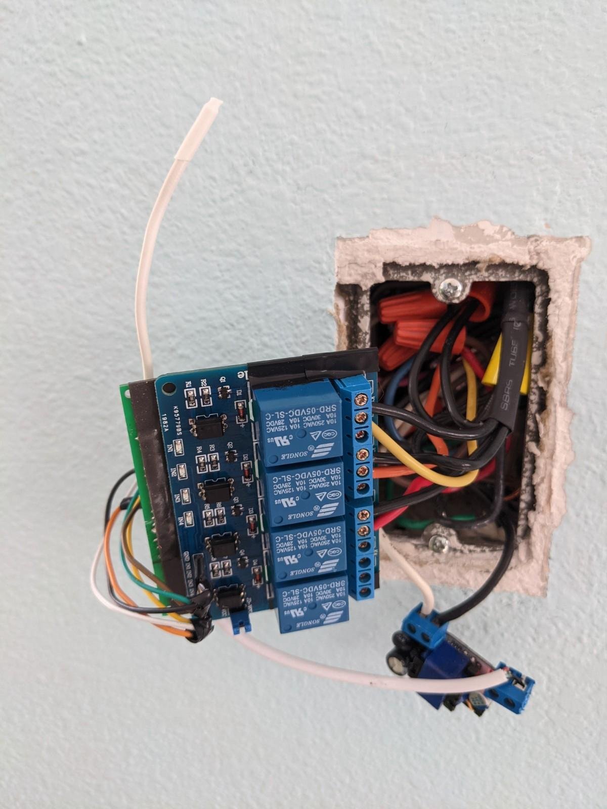
I had someone flip the breaker while I observed for smoke  , and all was good.
I then tested the set-up from my Hubitat controller... having added the device as a Generic Z-wave Dimmer, I could send commands to set the "dimmer" to 15 (out of 100) to turn on the swamp cooler's water pump to wet the pads for a few moments then send the command to set the "dimmer" to 35 to turn on the fan to low, or 55 to turn the fan on high.
Now you can program rules in Rule Machine to control your swamp cooler however you like  !!
!!
Works like a charm.
I've been using this for 2 months now, No house fires.
The only hiccup is that the Z-Uno somehow became de-registered from my network and I had to manually remove it and re-associate it with my Hubitat Elevation once.
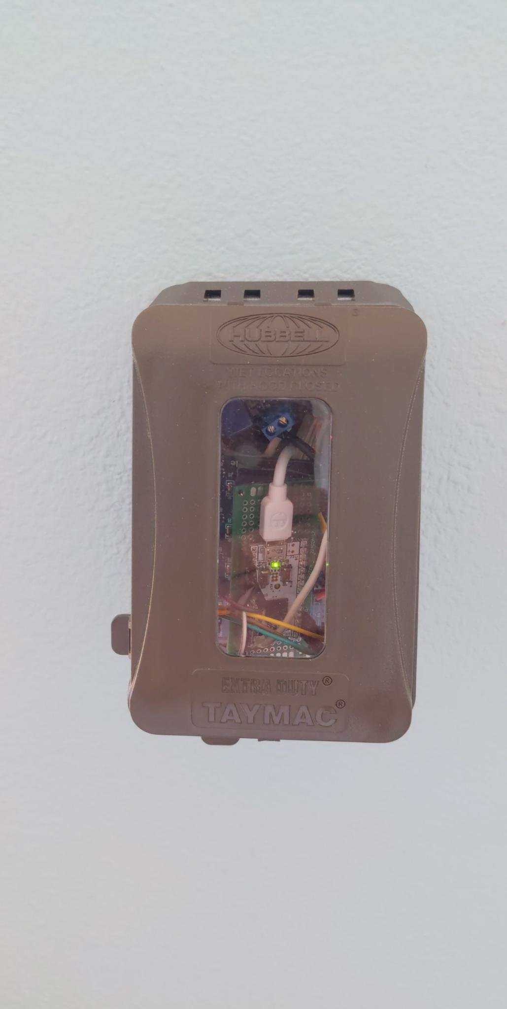
I couldn't fit everything in a single gang box in the wall where the original swamp-cooler controller was so I bought the expanding box cover mentioned above. Here's what it looks like - still not too clean, but better than letting it just hang out of the wall:
Hope this helps someone else who was wondering why there are all sorts of Z-wave controlled thermostats, but no Z-wave controlled swamp-cooler controllers...
Sean

