Please show us a picture of your "wall-mounted Liftmaster button (w/ light button)". If it looks looks like a really old doorbell button, then maybe you can.
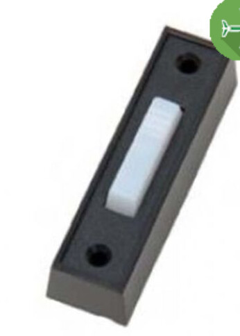
Otherwise, the option above from @aaiyar is probably your best bet.
Please show us a picture of your "wall-mounted Liftmaster button (w/ light button)". If it looks looks like a really old doorbell button, then maybe you can.
Otherwise, the option above from @aaiyar is probably your best bet.
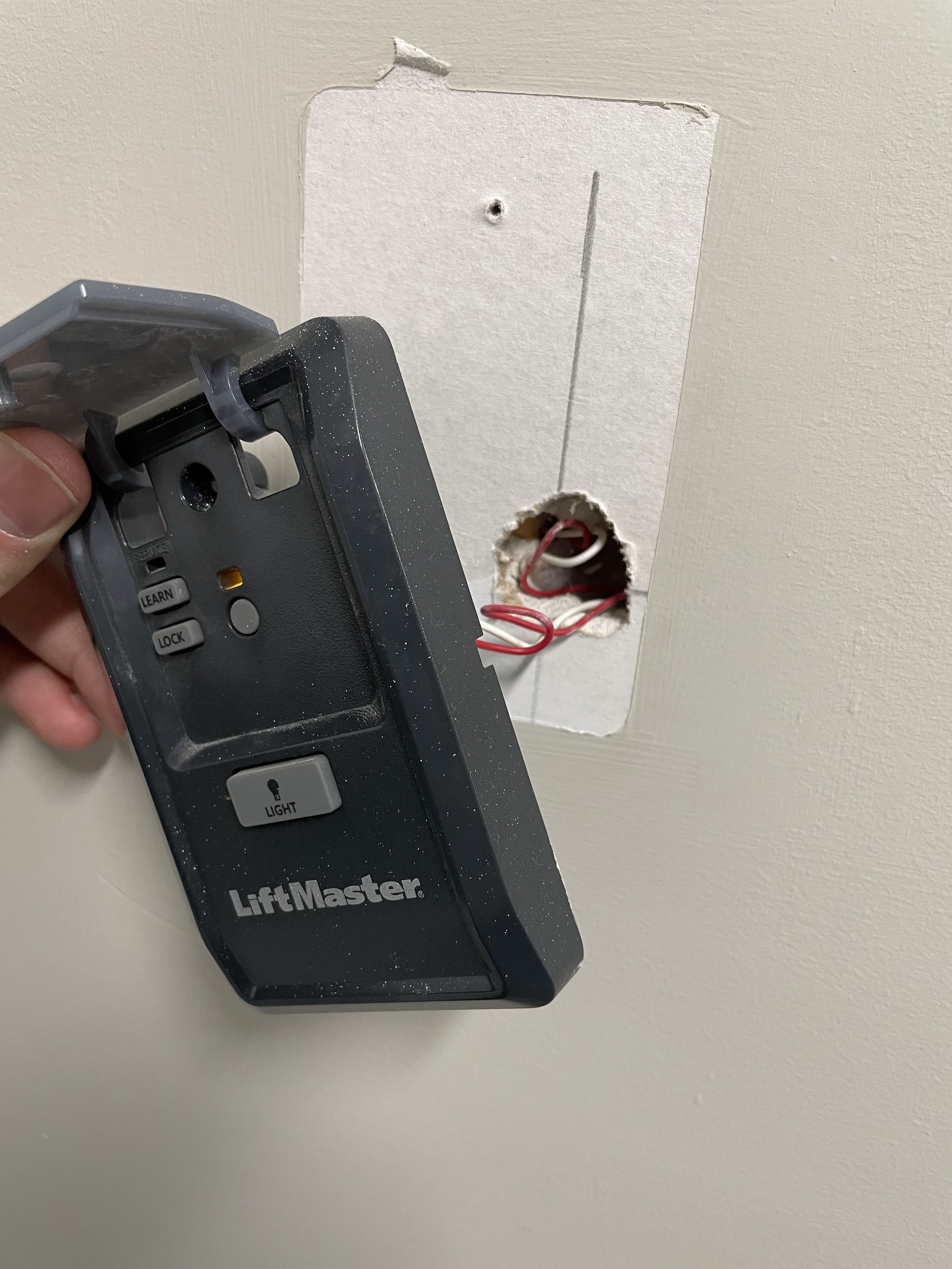
Here's my wall switch:
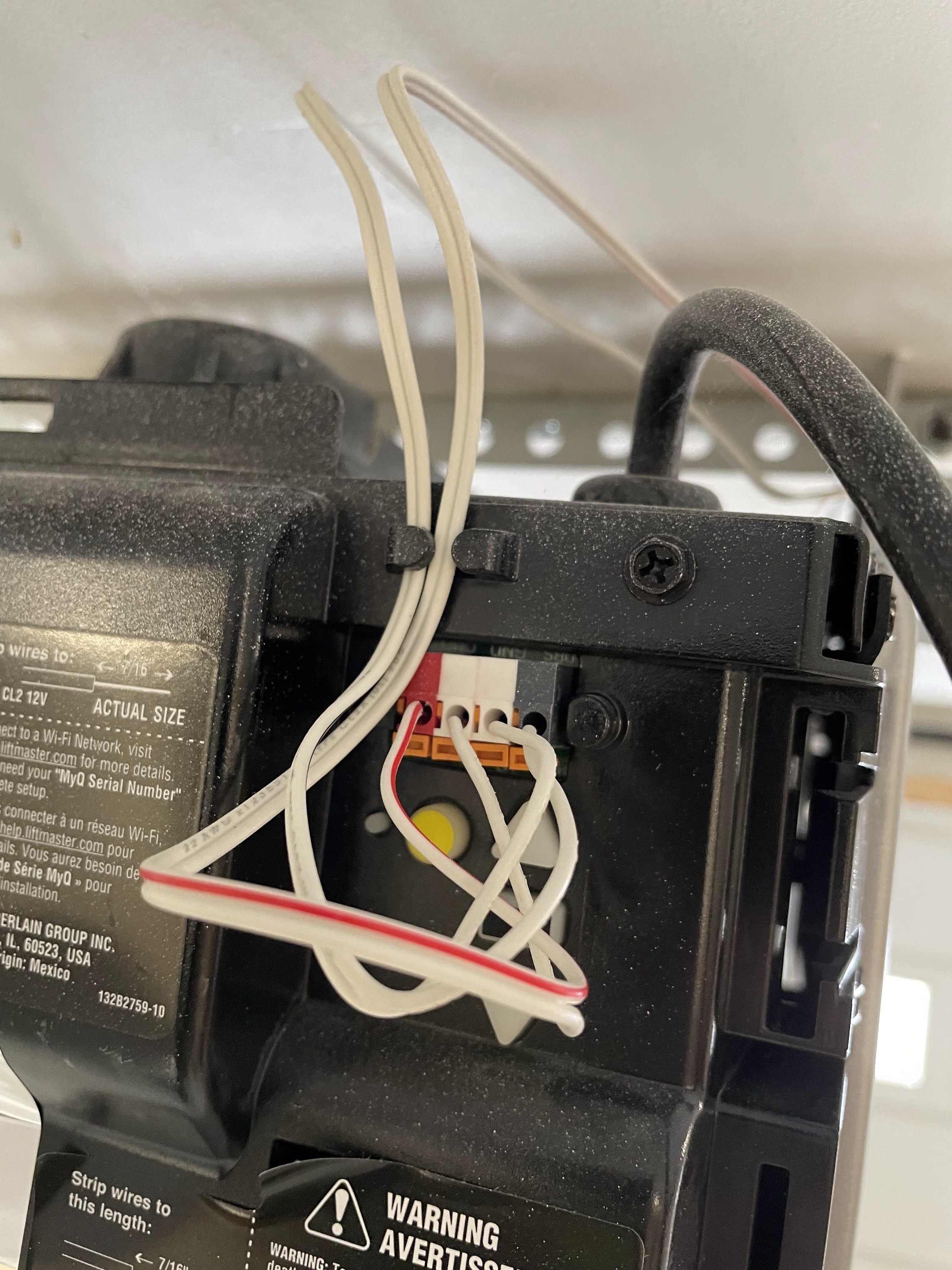
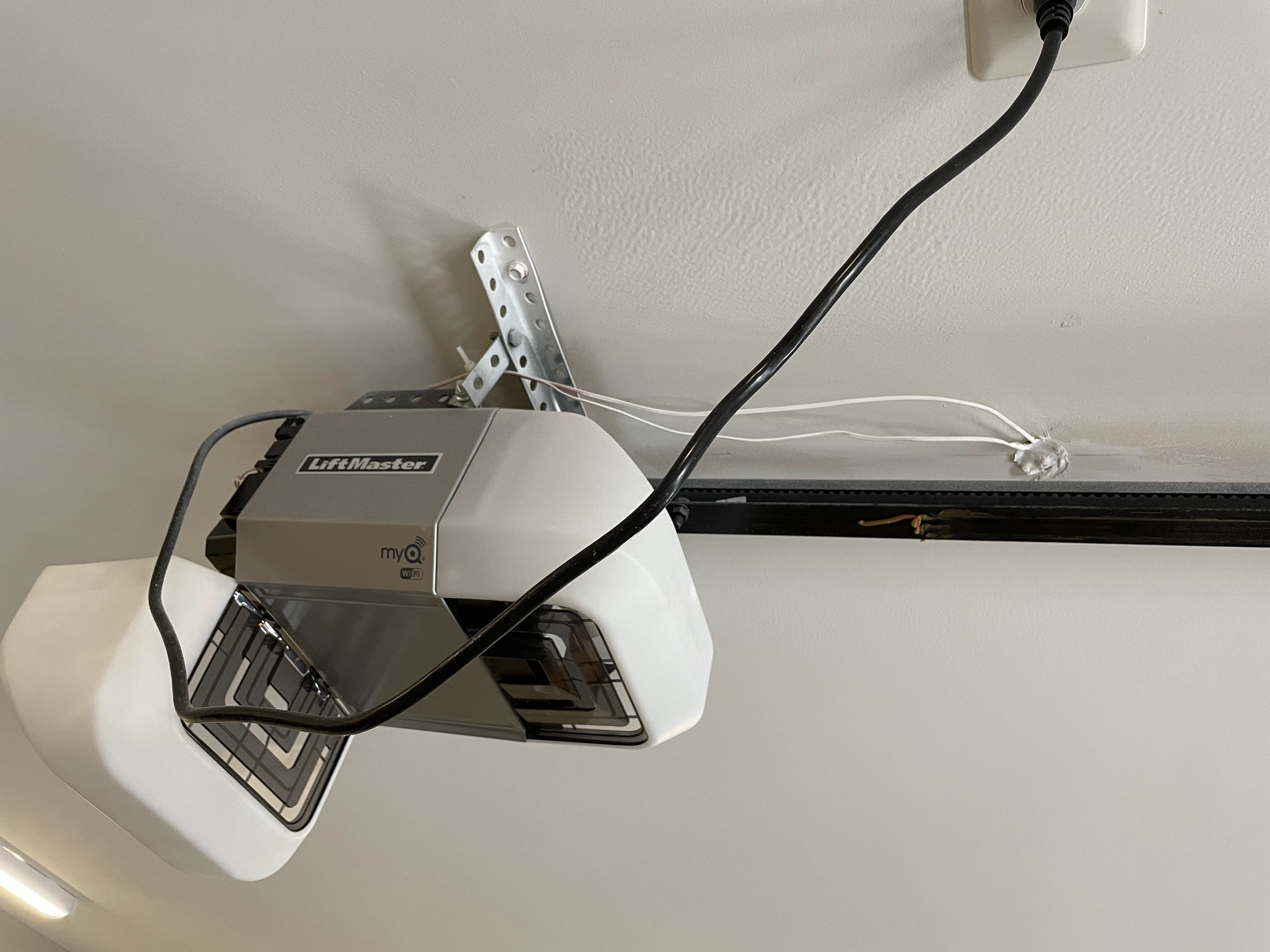
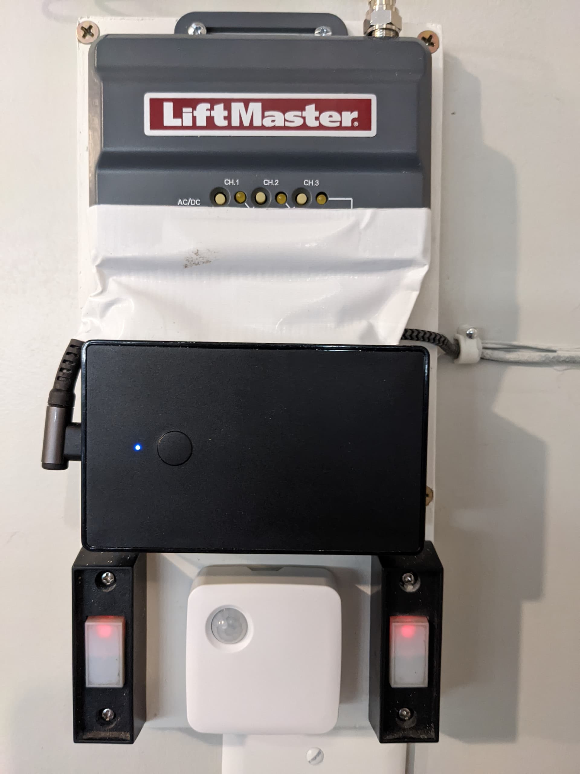
This is my Chamberlain Liftmaster MyQ GDO:
Here's the 2 sets of wires going from my GDO to the ceiling (not sure exactly where):
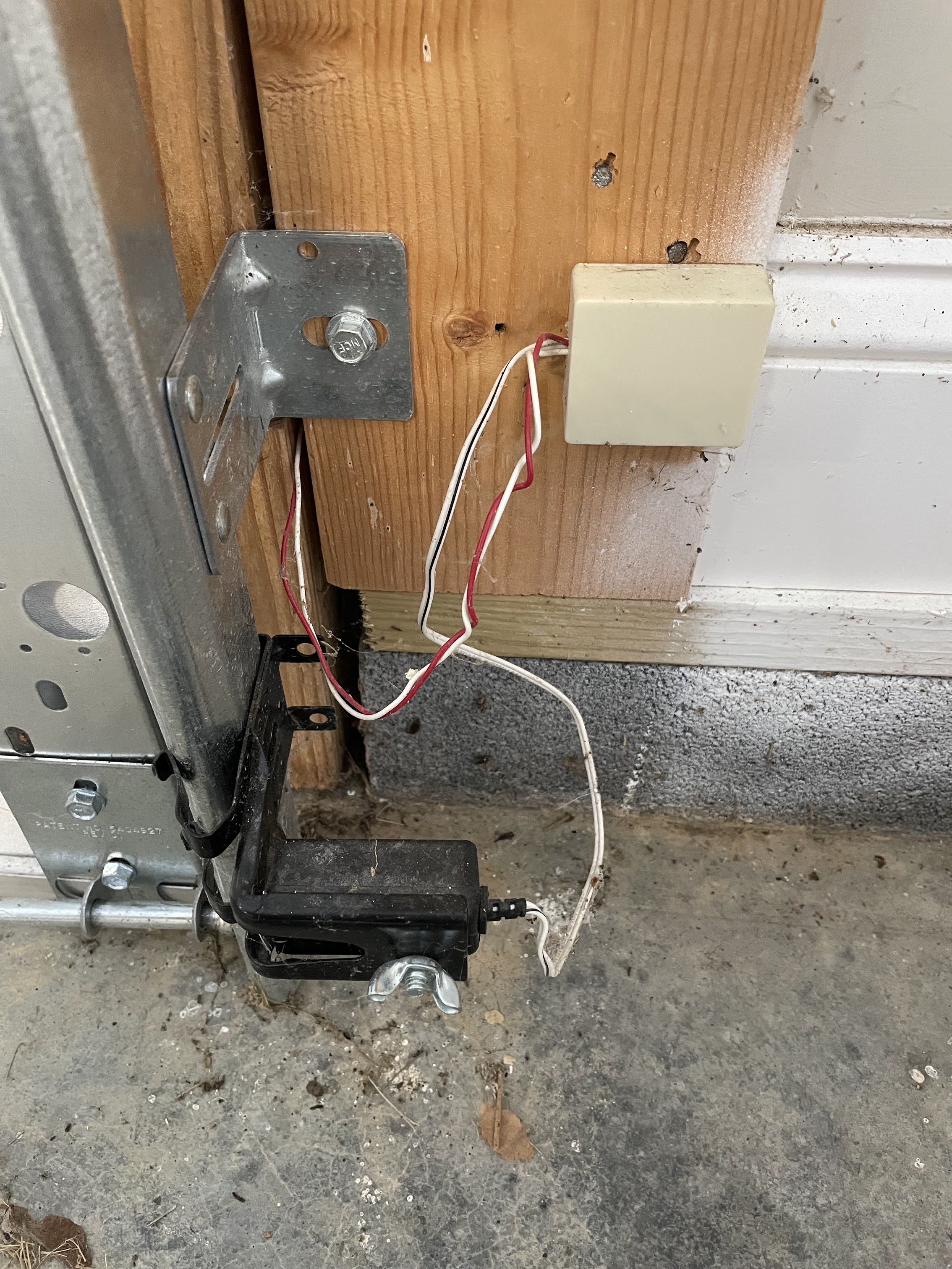
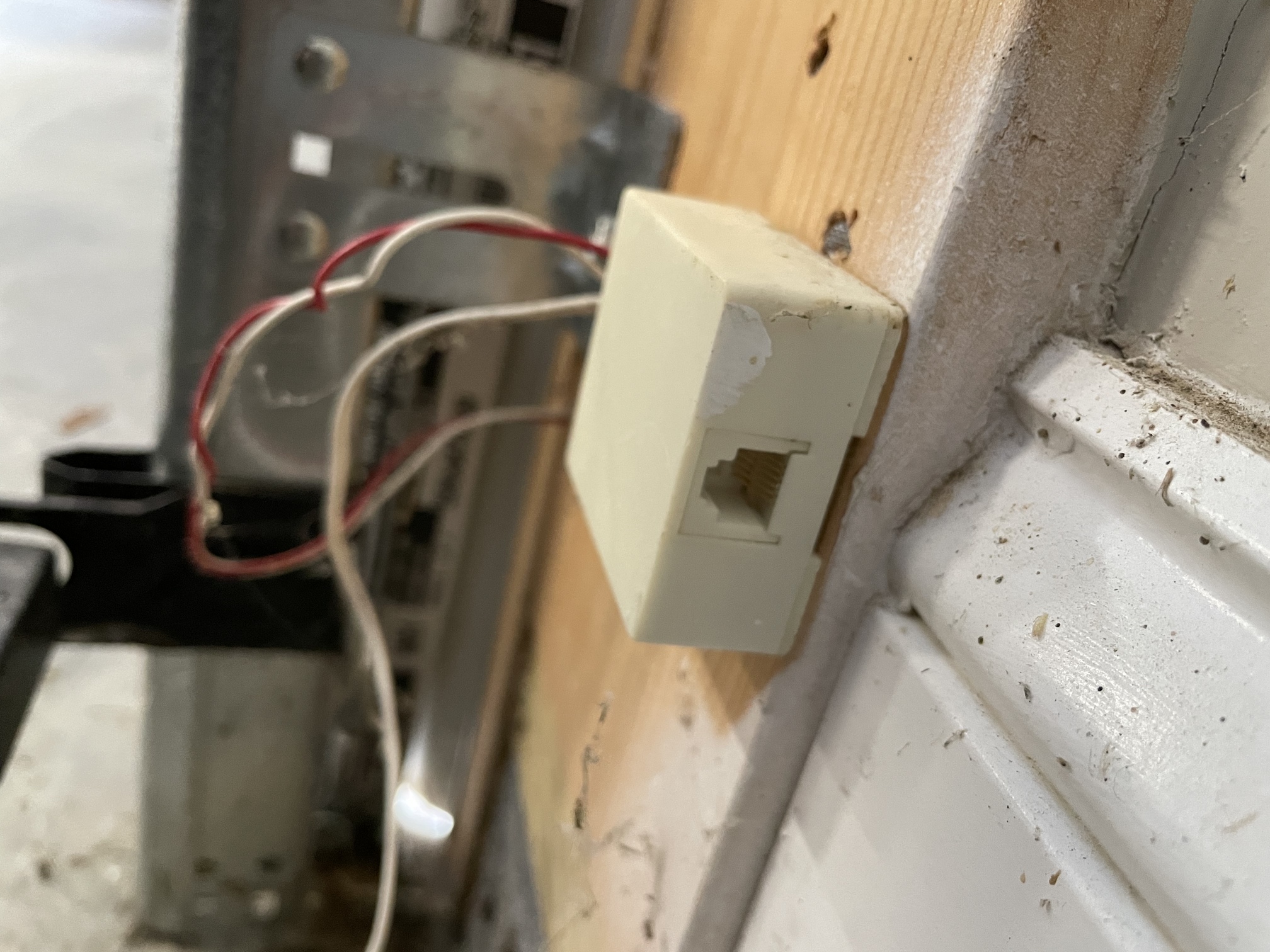
Here is one of my photo eye's, there's another one wired identical to it on the other side:
I think the wires going to my wall switch are coming straight from the breaker bc they don't look like the ones going into the GDO. The ones going into the GDO look more like the ones attached to the photo eyes.
So does this mean my wall switch is sending a wireless signal to the GDO? If so, then how would I incorporate my ZEN17 in this whole setup? I thought the wall switch ran wires directly to the GDO, but this is obviously all way over my head even though I feel like it shouldn't be.
I know I can use the Liftmaster switch from Garadget, but I'd like to do this with what I have already if possible, but I'm still open to that route.
That very last pic (eye sensor) is a headscratcher - the "loose" wires coming in from the frame sure do look like the loose wires attached to your wall switch but that makes no sense to me... If you take the cover off that ivory box there, what does the inside of that look like?
I've never seen anything like that before (ha, not that my experience is very vast!)
ETA2 -- Does the other eye sensor have those extra wires and a junction box like that too? Well, I guess they're not extra per se - it's still just 2 wires going somewhere -- I'm just confused what the purpose of that box is
I feel the same way. There must be something going on in that box. It doesnt make sense that its just the joining of those two wires.
I picked up a used remote off of marketplace and just sacrificed that to make life easier. the entire setup sits inside my house and I didn't have to mess with the GDO wiring at all. Its been working great. Also controls more than one door.
Your pictures are helpful and you will need to either buy a Garadget button or follow the instructions to modify one of your buttons.
Well I’ll be darned- it looks like an RJ11 port on the side of that box beside the photo eye… And yes- the photo eye on the other side is the exact same setup- ivory box and all. No idea what this is for.
Also, @hydro311 the wires going into the crack between the garage door and the frame seem like the ones connected to the GDO, not the AWG bell wire attached to the wall switch.
My guess is that your house was pre-wired for the GDO with the RED and WHITE wires to each of three locations (two sensors + 1 button). The installer of the GDO used those white boxes to contain the splice to the wires that came with the Liftmaster GDO hardware. My guess is that tucked up into your ceiling, above the GDO, the wiring from your wall button are spliced to the wires going to the GDO unit.
Yeah I read your DIY post many many times lol but what hangs me up is the difference between your Zen16 and my Zen17 (which I know has already been explained to me, but electrical concepts just seem to elude me) has been stumping me.
And the nice long write up from Zooz on their website for the zen16 is great, but I wish they’d do one for the zen17 too.
You've gotta be right since there's only two 2-wire cables at the GDO - one cable is for the switch, but the other sensor cable must be a pigtail coming from a junction box somewhere where it connects to the 2 sensor cables (1 from each eye sensor).
It sure would just be nice to have access to those junction boxes, but I fear they're drywalled over.
I can't say I've gone thru that guide with a fine-tooth comb looking for differences, but as far as I can tell, everything in that guide would be applicable to Z17 too. I referenced that guide a lot to sanity-check my wiring & setup when I did my Zen17 -- I don't recall any missed/different info.
I wish I could help with the security-related wiring, but assuming those sensor and wall-switch junction boxes are mudded over somewhere in walls/ceiling, that leaves the only decent access to the wall switch wiring to where it comes out of the ceiling.
If I were you, I'd consider ceiling-mounting the Zen17 somewhere up around the GDO -- that gives you access to the wall switch wiring and the ability to tuck the garadget thing somewhere up around there too. Use the other (hopefully open) outlet on the GDO's receptacle to power the Z17.
So the AWG bell wire from my wall switch does run to the GDO, just spliced with something else?
So if I get the Security 2.0+ dojigger and mount it and the zen17 to the ceiling next to the GDO, what would that wiring look like? Sorry to ask for such explicit instructions…
The wall switch wiring is junctioning somewhere - the "loose" wires in your wall switch picture are individually sheathed, but the wall switch cable at your GDO is just plain bell wire. I don't know why they would've done that junction**, but it happened - that definitely ain't the same cable at one end from the other.
** - I can't think of anything additional that would be involved in that junction - dollars to donuts, I bet they simply spliced together two different types of wire/cable. In the sensor junction box (wherever that is), it would seem they junctioned the 2 sensors so they could then just run one cable to the opener. That at least makes some sense.
You'd have to refer to your opener's manual to verify which wires are connected to which inputs on your actual opener (red/wht/blk inputs), but 2 wires are from your wall switch and two wires are from your sensors.
Edit - junction clarify
Not sure if this was answered.. The difference in the zen17 from the 16 is that you hook one wire to Normally Open (NO) contact and then the corresponding "C" right next to it. On the 17, there are two relays and each one has a separate Open and Closed with the C next to it. Other than that.. works like a charm. I have mine in the basement since its right next to the garage. Works great with the zoon garage door app.
Will this work with the zooz16 relay?
Where in the relay would each of the 3 wires be connected to?
Here's a guide for DIY'ing two doors.
Yes
Finally implemented this:
It's not quite done yet - I need to 3D print a cover for the wires to replace the temporary piece of duct tape, and replace the single switch plate with a double so I can add a Pico remote for the driveway lights.
The Liftmaster receiver is connected in parallel with the buttons, to the inputs of the Zen16 box. That way Hubitat detects (and can log) remote and manual opening, not just when Hubitat does it via Z-wave.
The receiver's 3rd channel is connected too even though I only have 2 doors, since the Zen16 reports the inputs even if the output relay isn't connected to anything. That lets the 3rd button on the remotes toggle the garage and driveway lights between their current settings and full brightness, to help with parking at night.
The only problem I'm having is with Alexa. If I tell her to "close garage main door", it works immediately, but then tells me about 30 seconds later that it was unable to do it. I haven't tried to track that down so I'm not asking for help (yet), but other than that it's working well.
Download the Hubitat app