Searched for the battery on Lion Wholesale and found quite a few...which is the "right one?"
They have ones labeled "protected" and ones not so labeled, and varying amps and and mAh levels....
Thanks!
Searched for the battery on Lion Wholesale and found quite a few...which is the "right one?"
They have ones labeled "protected" and ones not so labeled, and varying amps and and mAh levels....
Thanks!
Here's a question: If this micro USB charging board completely drains the battery during a power outage, when the power comes back on will it automatically start charging the battery again and also power the attached hub? Or, will it require some kind of reset?
I'm asking because I've learned that some UPS devices require a reset after all power is drained.
Thanks.
In summary, I don't know ..... yet. But, currently my opinion is the running out of power then restarting question you asked will NOT work. The IC on the UPS board have the basic functions for this to work but my limited experience is the board going from lack of input power to shutdown is not clean enough for the Hubitat the be safely protected.
My current status:
My UPS board has been benched due to other priorities. Up to now I've only performed two tests.
Ran the UPS with power for ~2 weeks with no issue.
Ran the UPS with power Removed for 6 hours. After about 4 hours the board seemed like it wasn't creating enough current to keep the Hubitat running. I have a relatively low power battery (LG w/2500 mAh). Unfortunately I wasn't paying close attention and had no data acquisition connected.
With Isaias my motivation has increased significantly as I had trouble getting the Hub back after the repeated ON/OFF/ON/OFF/ON/OFF then OFF for 4 days.
I will report back when I have more to share. Hopefully within a week or so.
Wow, you had a real use case for this UPS board! I appreciate your response and am looking forward to your future comments.
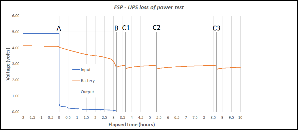
Results of my bench test of an ESP32S UPS board (as linked in post 59)
Goal: To determine how the UPS reacts to running completely out of power in a loss of power event.
Setup:
Resulting data:
Explanation:
The annotated points:
Additional Observations
Once the UPS passes point B, the system will not recover with when the mains returns. This is a result of the charging IC dropping the charging current to below 100 ma for a more "gentle" charge of a battery below the 3V mark.
Conclusion:
This combination is NOT Suitable for use as a continuous UPS without additional capability. By this I mean well before the 3 hour mark (for this test) the hub needs to be shutdown. Even with the hub shutdown its current draw is not 0 but 60 ma.
I recommend shutting down the hub programmatically at about 2 hours. Then physically disconnecting the hub as soon as possible.
Logic for determining the simulated load
In normal operation a hub "idles" at ~ 300 ma. When the radio(s) are active the current jumps to about 600 ma. So the larger the system the more time it spends at 600 ma. This test at 450 ma is probably equivalent to a fairly large system.
John
@JohnRob, thanks for the excellent test results and comments!
I'm thinking of the following use case when I'm on vacation and away from home:
Under this scenario, the hub is still drawing power from the battery while shutdown, so it can potentially fully drain the UPS board battery. Now, the main power comes back on. Will the UPS board power back up automatically and provide power to the hub so it boots up? From your test results and comments, it appears the UPS Board will need to be manually reset to begin working again, correct?
Excellent work. Thank you for doing & sharing this, but I'm not sure how this plays out in reality, as I indicated above I got almost 8 hours, with a slightly larger capacity cell, the 3400-3500 mAh Panasonic cell. Based on my real world observations, the constant draw of 450 mAh is too high for reality, unless during a blackout you decide to play with your large system, and have tons of rules running.
If people want to play it extremely safe and shutdown at 2 hours, i guess that makes sense, as how many automations will successfully occur during a blackout? Your lights are already out and your garage door is out.
I was mostly concerned with HSM functioning during a blackout or in case someone decides to yank my electric meter before breaking in(I've since put a padlock on it) and for those slow activity periods, the C4 hub ran for almost 4 times as long as this simulation. When the time was up, I just reconnected power to the wemos board and it continued to run without issue.
Granted I purposefully avoided interacting with the hub during the simulated "blackout", so I certain that lowered the current draw.
Fully draining the battery would take quite a while, with the hub in shutdown mode. I guess it's feasible that the board would eventually supply power to the hub, but how long would that take.
We might be able to use a wifi plug to switch power to the wemos board? although if power is out...
@Rxich,
Whether the 450 ma is reasonable or not is irreverent. The stated goal of the test is determine what will happens under a complete drain of the battery. It was not my intention to estimate actual time to battery depletion.
My intent was to understand how the UPS reacted to these conditions as my personal goal is to insure my hub does not loose power in an unstructured manner and maybe even survive short term blackouts. My experience with blackouts in our area (Connecticut) are they are a few minutes, maybe as much as 20 minutes OR days. There seems to be no in between. So the difference between 2 hours and 8 hours is meaningless to my situation.
Will the UPS board power back up automatically and provide power to the hub so it boots up? From your test results and comments, it appears the UPS Board will need to be manually reset to begin working again, correct?
The board WILL NOT START UP after the battery is completely depleted. You will have to disconnect the hub, allow the battery to charge to above 3 volts. It took mine about 40 to 45 minutes. Then reconnect the hub.
I'm working on a simple relay implementation to disconnect the hub completely at the end of battery life but it would violate the "no soldering iron" goal. I'll probably not post this unless I get requests for such a configuration.
Important Note, fully depleting a battery is not good for battery life. It would be relying on a device that is for protection not normal operating cycle. It would be similar to using a fuse as the normal part of a circuit operation
John
This will be the last post on this topic (unless questions come up).
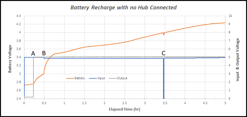
After the over discharging in post 86 I measured the charging process with NO HUB Attached.
Explaination
Quick data check:
Battery is 2500 mAh
charging at 600 ma for 4.5 hours = 2700 mAh. Close enough to believe the numbers are correct.
Conclusion
If one discharges the UPS battery to the point the circuits shuts down, you should allow it to charge for a minimum of 1 hour without the Hub connected. This is important as once the Hub is connected to the UPS the 600 ma charge current must now charge the battery AND power the Hub.
When the Hub is consuming 300 ma, the battery only has 300 ma charge current.
When the Hub is consuming 600 ma the battery is not being charged.
John
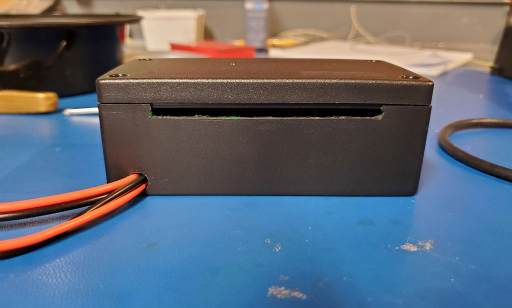
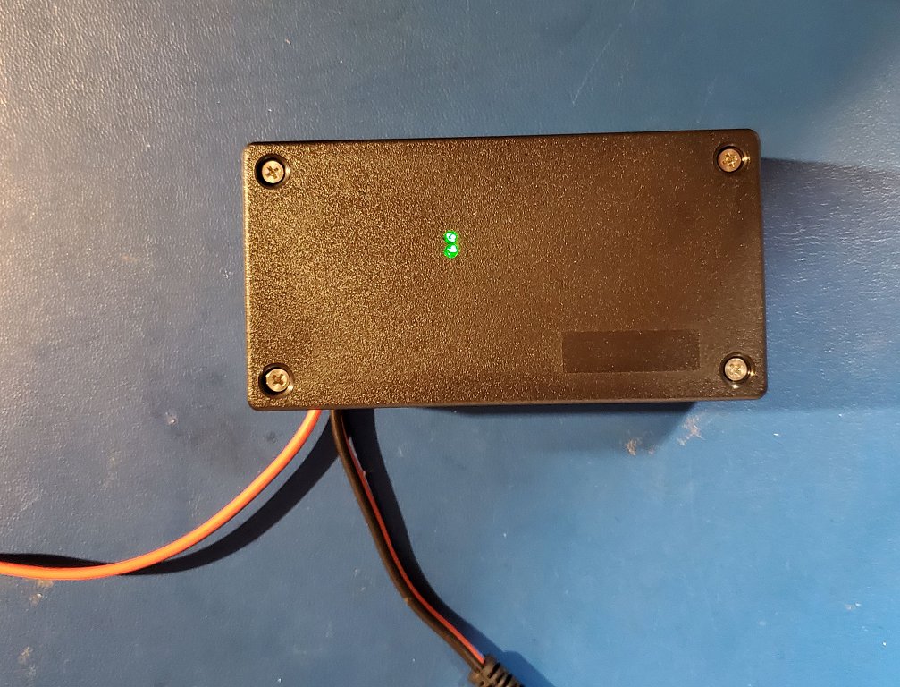
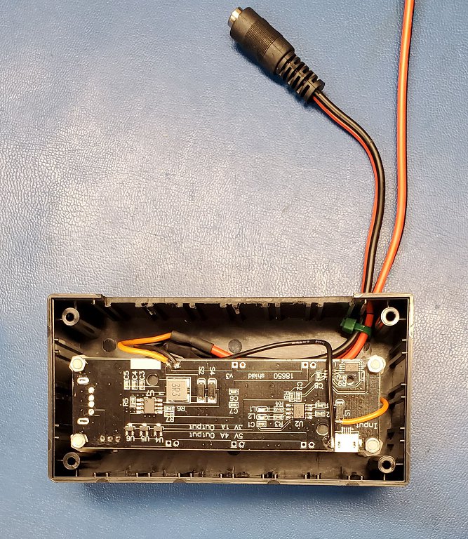
Finished UPS:
Attached is my final product. I'm not happy about how the slots came out but my trimmer router would not go slow enough to make a good cut.
John
UPDATE 12/2022
This board had two different brand 18650 batteries fail. The first one after about 10 months, the 2nd about 2 - 3 months. I've tossed this UPS. I feel keeping the battery at 4.2V all the time and never discharging it is not good for battery longevity.
Looks good.
Question: What's the purpose of the slot? Also, are you now using this to act as a UPS for your HE hub?
Yes
There is a bottom slot in the "front" and a top slot in the "rear" they are to allow air flow so any battery heat can escape.
I could have used holes but its harder for me to drill a line of holes that look professional.
Nice work. The video below goes into great detail
 for only 2$. Is this possible? (Raspberry Pi, Arduino, ESP32)")
Ok, that makes sense. I didn't know that this small board could generate enough heat to have to mitigate it. I ordered the same board from Banggood and have to wait until October before it is suppose to arrive. I may do the same thing as you, and put it to use as a mini-UPS for my HE Hub.
It will likely not generate that much heat, I was just being conservative.
I really doubt this setup will generate any significant heat, based on the 600ma limit on charge current.
BTY I used this box from eBay: "Enclosure 4.5" x 2.34" x 1.68" inches Electronic Project box"
I'm thinking of this scenario now:
So now, how can I restart the Hub? My understanding is that I have to completely turn off the hub (by removing the usb power) and then plug it back in. With the HE hub connected to the Wemo board via USB cable, I can't disconnect that power remotely.
I was thinking of using a SONOFF WiFi USB Smart Adapter, which I would connect between the Wemo Board and the HE Hub. However, I don't know how many amps this adapter would consume from the battery while active.
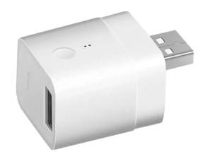
Any thoughts on this idea, or alternate method? Thanks.
I think you have a very good approach. I would however be concerned on how long an outage you wish to accommodate. If days, the current from the adapter my still consume the battery to depletion. Then restarting might or might not be a issue. However for $6 - $7 I think it is worth a try.
You should also test how happy your router and this device are after losing power and reconnecting.
I'll keep thinking and let you know if I find a simple solution.
John
I live in Seattle, WA so we rarely have power outages that will last days. Typically an outage will last less than 1 hour, so my main concern is being able to safely shutdown the HE Hub when necessary and restarting it after power is restored remotely when I'm not at home or gone for an extended amount of time. Maybe I'm a worry wart, but since my hub controls the scheduled lights, etc. I'd like to make use it's up and running while I'm vacation.
Thanks for your comments!
I've been thinking about this a lot lately. I think I'd like to design a small board using a diode or circuit to take in 3 5v sources. I'd bias the diodes so that one input is "primary" and the others are secondary/tertiary. My thought is to power the primary from a powered source (wall wart) and the other two from cheap batteries like these:
Then during a power outage the batteries could seamlessly take over powering the attached device...hub... if one battery became depleted, I could simply swap another in its place.
Nice thing is with a little logic, I could detect a power outage, and with a smart switch, simply power off all my AC sources for these devices.
Doing so would reduce the load on my backup power system, and there are a whole lot of off the shelf battery packs that I could use that would run the hub for Days....seems like if I kept the circuit very simple, it would be easy enough to have fabbed.
S.
Download the Hubitat app