Hehe, just match up the text on the PCB with the text on the lid.
I prolly wont do another run of these - not unless I redesign the PCB myself. The gent who designed it picked the worst possible SMD USB-C sockets and they were a nightmare to solder. I had to remove most of them and re-install them to get them to contact the hidden legs properly.
Cheers, it was a right PITA to print, so Im glad you like it.
Thank you, Im a bit of a perfectionist, so I put a lot of effort into getting them right. Plus I'd hate to send a faulty item overseas and inconvenience our 'Murican and Euro mates.
Good old Aussie Post, some days the service is amazing, other days it’s WTF!
I spent 3 years at AusPost in IT, (Major indigent manager, then project manager), so I shouldn’t be Surprised.
PS, one thing most folk aren’t aware of of, is 99% of international mail is carried in the holds of passenger aircraft. That’s why international mail was such a crap shoot during covid.
Most if not all USB A Chargers are going to max at 5v 2.4 amps. If they can do 9v they may able to reach 25 watts. Most USB A chargers that go above 12 watts will switch to 9V output. but not all chargers support that.
Is 20Watts really needed? If so does it support 9v for input?
I was going to use a USB C charger I have that runs at 5v 3amp, but that is only 15watts.
@dJOS would have to let us know if the charging circuit supports Qualcomm QC 2.0 or 3.0. The 3.0 QC can hit about 30 watts, but only when it receives a signal from the device being charged, which indicates "I can handle it all-give it to me"
Some chargers can go up to 65 watts, typically the "GaN" chargers
PS-above is an example, but I dislike the foldable prongs as they typically weaken and fold during insertion. I tried Viagra but the prongs were still floppy
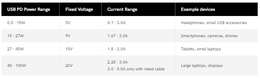
Well it is QC 2.0, 3.0 or some variation of USB-PD. All of them depend on some level of sensing resistor though once you leave the 5V power level as I understand it.
USB-PD as set range for different power output needs. The below graphic for USB-PD is old, but still kind of applies to what we are talking about. But I was pretty certain what @dJOS has said previously is that it didn't support all of these additional power stuff.
I also just looked up the original project and it looks like there it was only accepting 1 amp or so on 5V. Confirmation would be nice. I have a ton of chargers already so not really worried about finding one that will work, but it would e nice to be sure.
As you all are waiting I highly recommend the book "In a Sunburnt Country" for a wonderful and humorous history of one of the most interesting, and let's face it bizarre and dangerous countries / continents in the world.
The resistor thing is for proper detection of higher voltage needs. One of two things will happen without it.
You will get a strange condition where nothing will happen and for some reason the device will be seen as a peripheral device like the first release of the Raspberry Pi.
It will fall back to 5v if it decides it is a device needing power. Then you will get the needed power anyways. 5v is the fall back if nothing is detected for higher voltages.
It is still best to have it, but i would be surprised if it caused it to just completely not work.
The 4 port USB chargers will do this, I’m using one of these to drive my 2 hubs / ups’s.
SPLAKS USB Charger Plug, Universal International USB Wall Charger Plug UK/EU/US/AU 4 Ports Rapid 24W/5V 4.8A Multiple USB Charger with Multi-Protections Fast Charging Technology-White