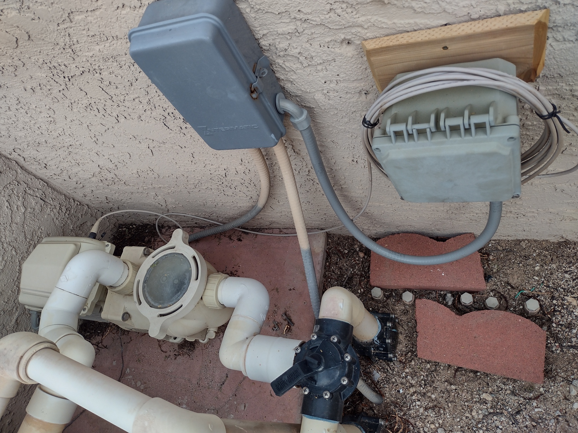
Now that the sun is up, here is a look at the overall arrangement. I was able to tap power from an old timer box. It is not clearly shown, but the control cable comes through a cable gland on the bottom (P7 or P9, I do not recall).
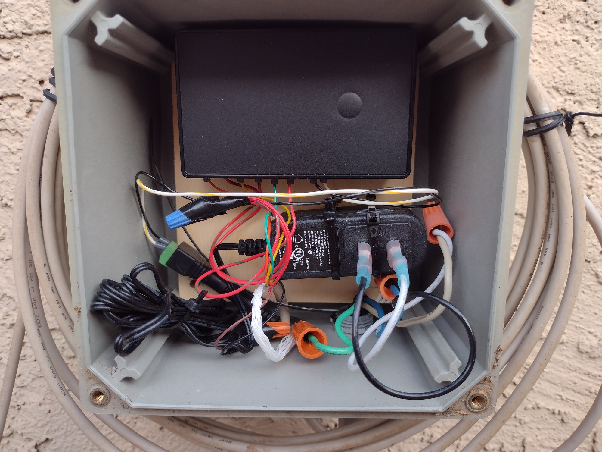
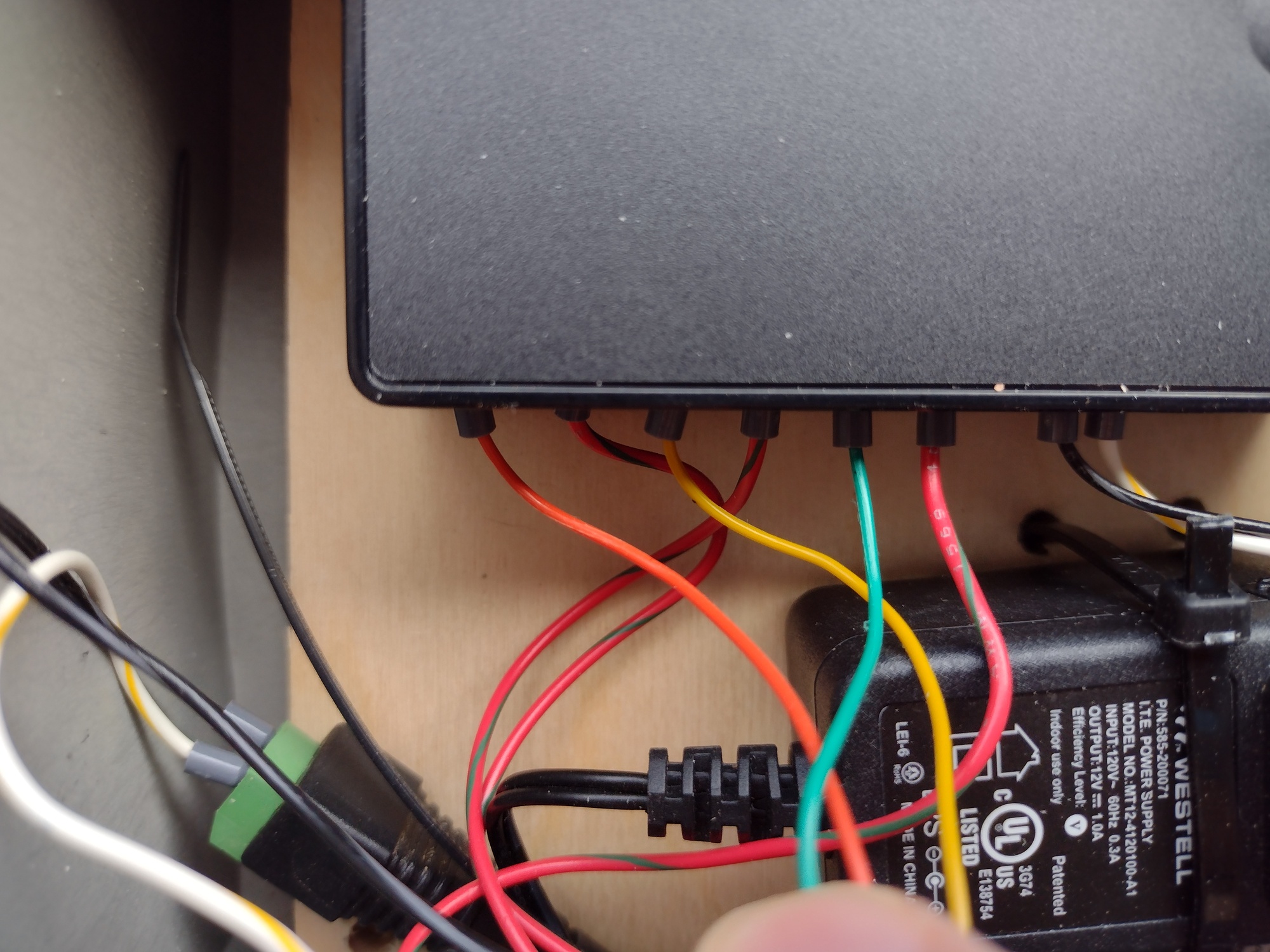
5V (red) wire goes to the blue wire nut, where it is split out to one side of each relay. The wires that I added to split it out are actually red with a green stripe.
Green/Yellow/Orange go to the other side of each relay for speeds 1/2/3, respectively.
A word of caution regarding the wire terminals on the ZEN16: It is designed for applications that would typially use 12AWG to 14AWG wires. The wires in the signal cable are much smaller (24AWG, I believe). To create a secure connection, I added wire ferrules (E0506 or something like that).
The enclosure is something that I had on-hand. If I was starting from scratch, I would consider using the Orbit 57095 enclosure.
The guts in my system are not even close to code, but orders of magnitude better than most electrical work that I have found around this house. Using the enclosure linked above would go a long way to having a professional-looking install.