Can someone advise on what device I need to control my Pentair SuperFlo VS? It looks like it’s 4 x 5v relays.
So I thought I had an Intelliflo and was going to use some custom stuff serial communications stuff that had been written to control the speeds, however it appears that SuperFlo VS (cheaper variable speed pump) can't do all those things, however it does appear that I can do the same thing using relays. The pump has 3 channels (actually 4 if you count the quick clean function) for you to select speeds and there is a communications cable that breaks out each channel into a relay. So can someone share with me how they'd tackle this with the fewest # of devices/most cost-effective but usable? Zwave, Zigbee, Arduino, or something different (raspi?), etc, all are fair game.
You might want to have a look at Nodejs-PoolController. That may help though I am not an expert on the details with a standalone pump setup. Some others are working on it - more chat on the gitter here.
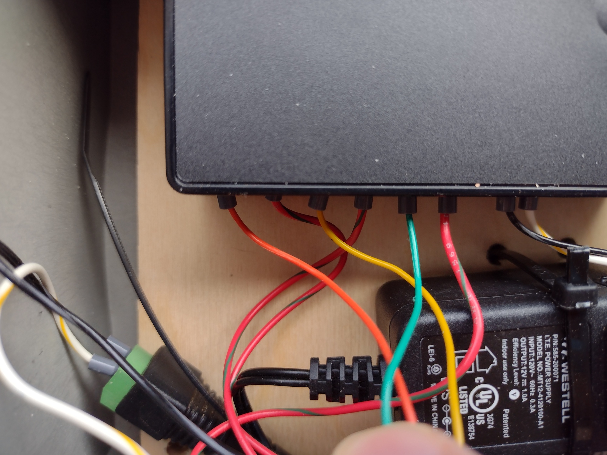
Hey Brian. I wanted to confirm something that I saw in your pictures. I also have a SuperFlo VS and bought the communication cable. It looks like you joined the Red (5V) wire to a wirenut with 4 other wires (Black/Red) and then connected it to one terminal on each relay. Then the Green (Speed 1), Yellow (Speed 2), Orange (Speed 3) and Brown (Speed 4) cables to the other terminal on each relay. Am I seeing that correctly? Also, where are you connecting the Black Ground wire? I'm not using a LinkNode but a Zen16 MultiRelay. I only use 3 speeds so it's not a big deal that it only has 3 relays but I don't want to wire it incorrectly.
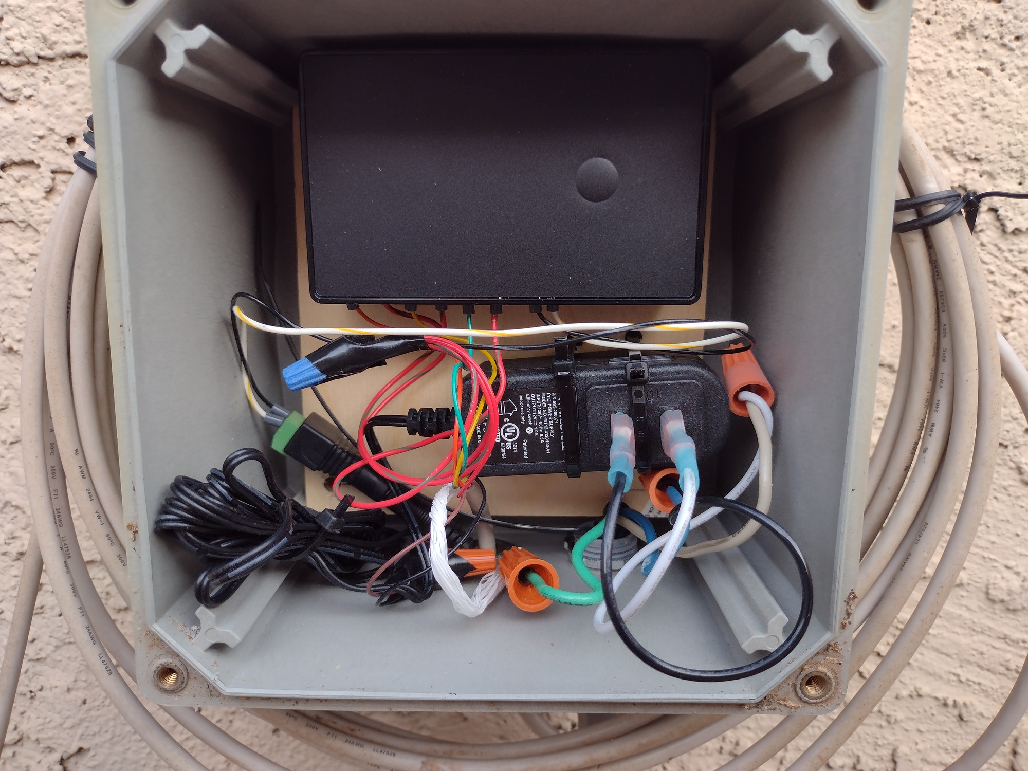
This is how I have it wired. The +5v is used to connect to the different colors which triggers the speed changes. You can see the red going to the wire nut and then connecting to the other side of each relay.
That makes sense. So ground isn't used in the case because the Red wire is the common and is supplying the 5v and the individual wires green, yellow, orange, brown are the individual speeds?
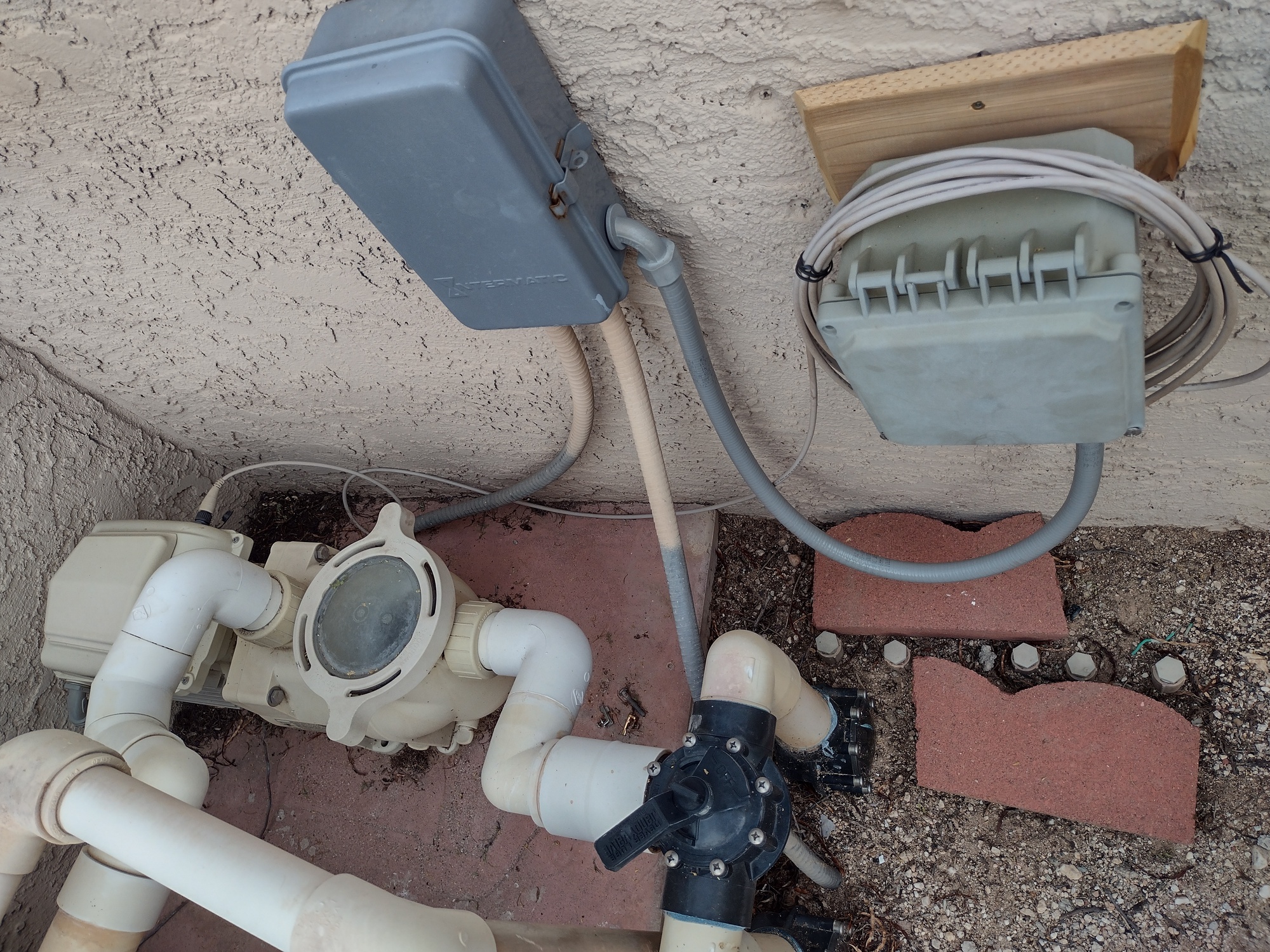
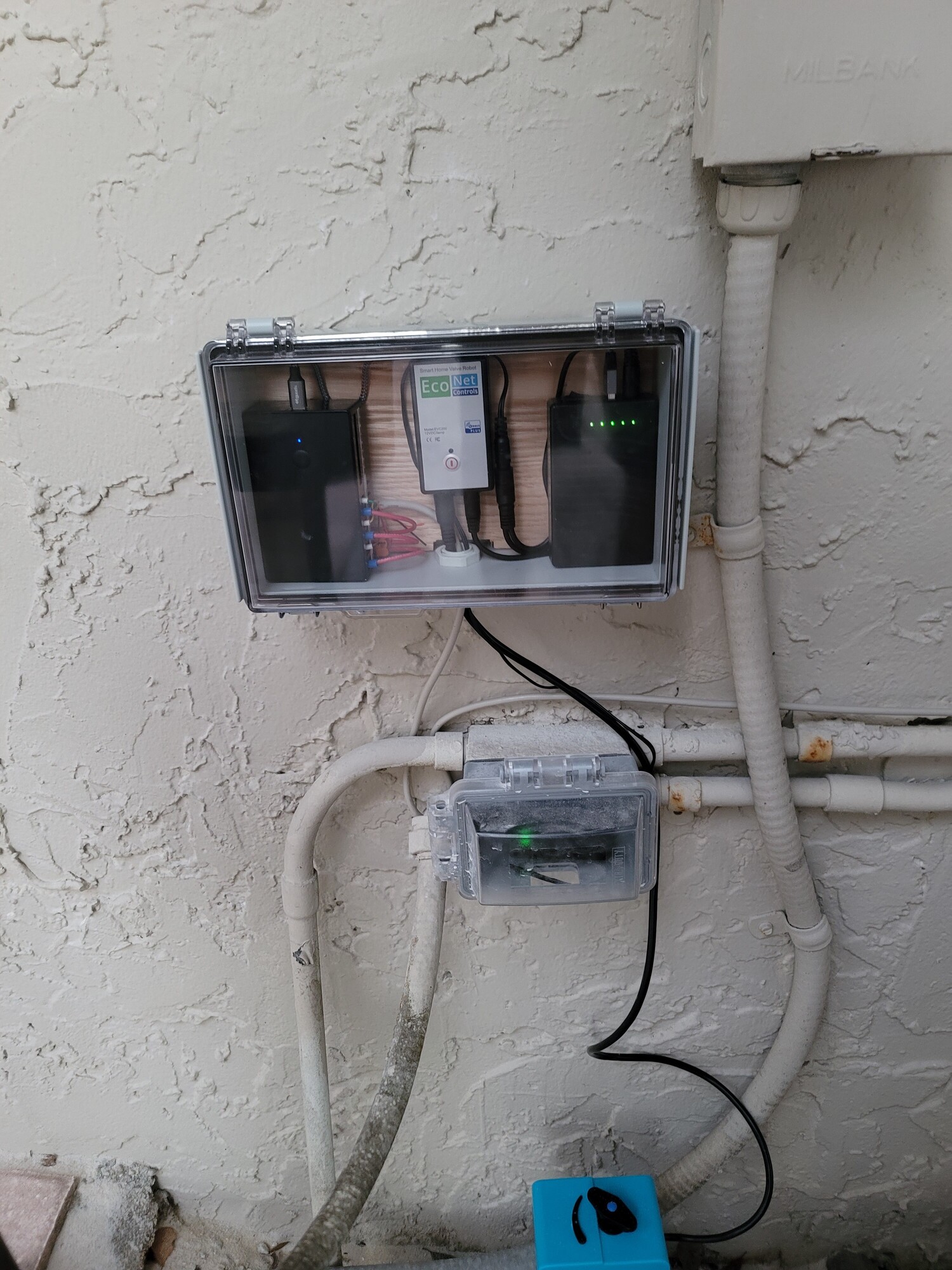
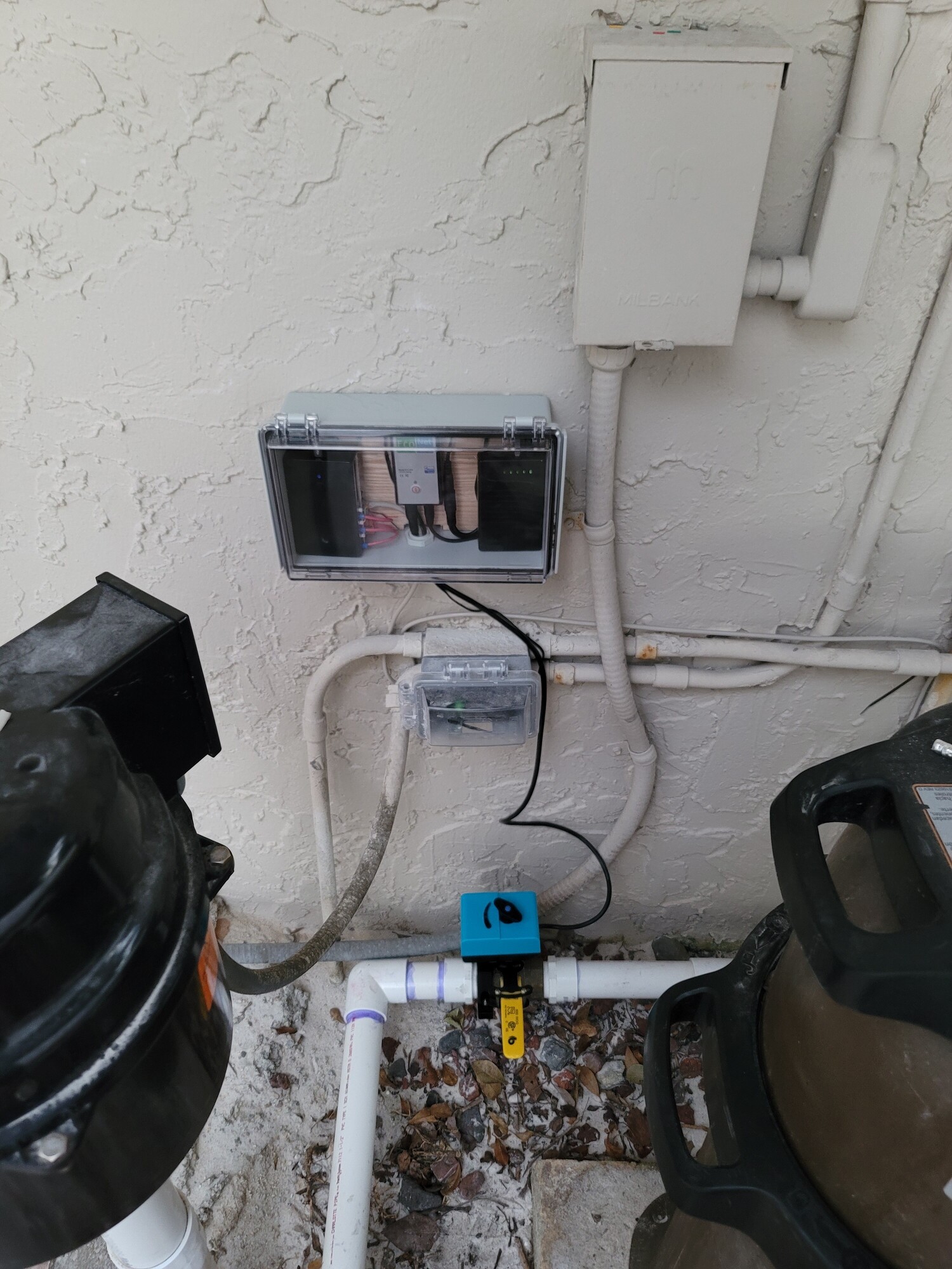
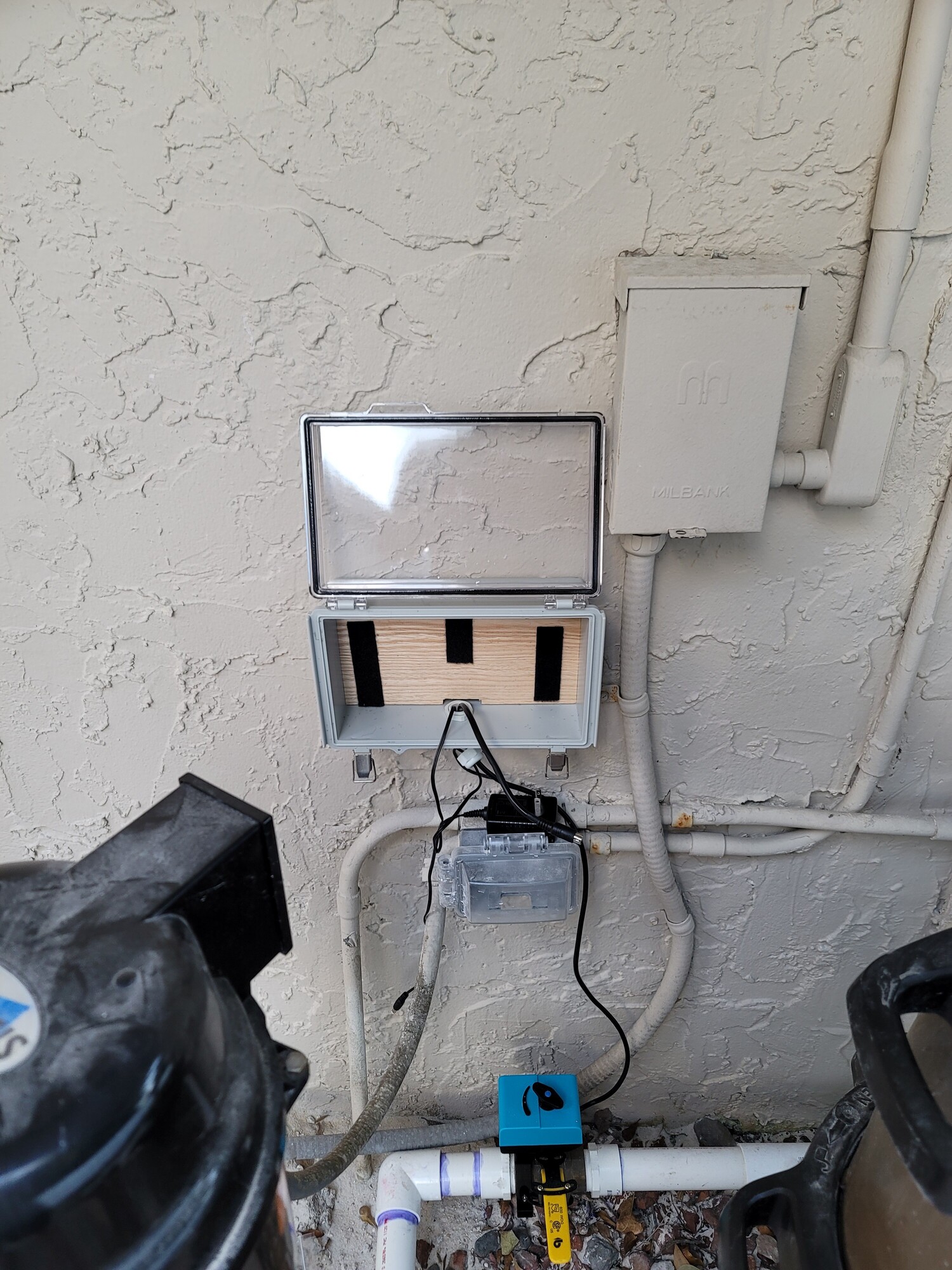
Now that the sun is up, here is a look at the overall arrangement. I was able to tap power from an old timer box. It is not clearly shown, but the control cable comes through a cable gland on the bottom (P7 or P9, I do not recall).
5V (red) wire goes to the blue wire nut, where it is split out to one side of each relay. The wires that I added to split it out are actually red with a green stripe.
Green/Yellow/Orange go to the other side of each relay for speeds 1/2/3, respectively.
A word of caution regarding the wire terminals on the ZEN16: It is designed for applications that would typially use 12AWG to 14AWG wires. The wires in the signal cable are much smaller (24AWG, I believe). To create a secure connection, I added wire ferrules (E0506 or something like that).
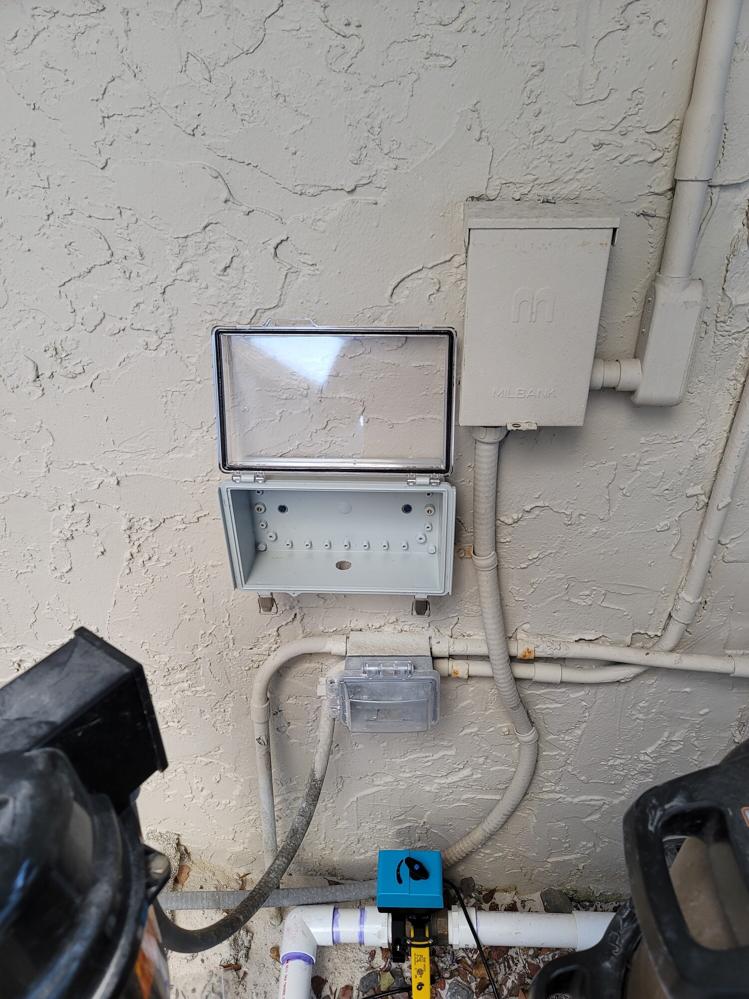
The enclosure is something that I had on-hand. If I was starting from scratch, I would consider using the Orbit 57095 enclosure.
The guts in my system are not even close to code, but orders of magnitude better than most electrical work that I have found around this house. Using the enclosure linked above would go a long way to having a professional-looking install.
This is great. I'm waiting for the cable to arrive and then I have some electrical work to do to get this ready to go. Once I'm done I'll post pics as well.
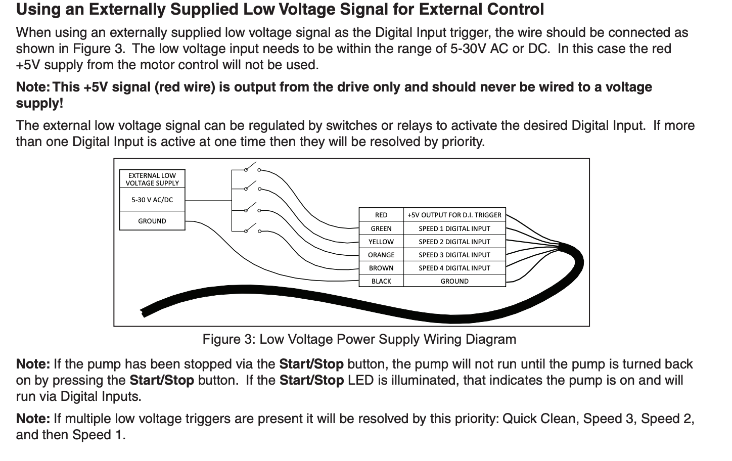
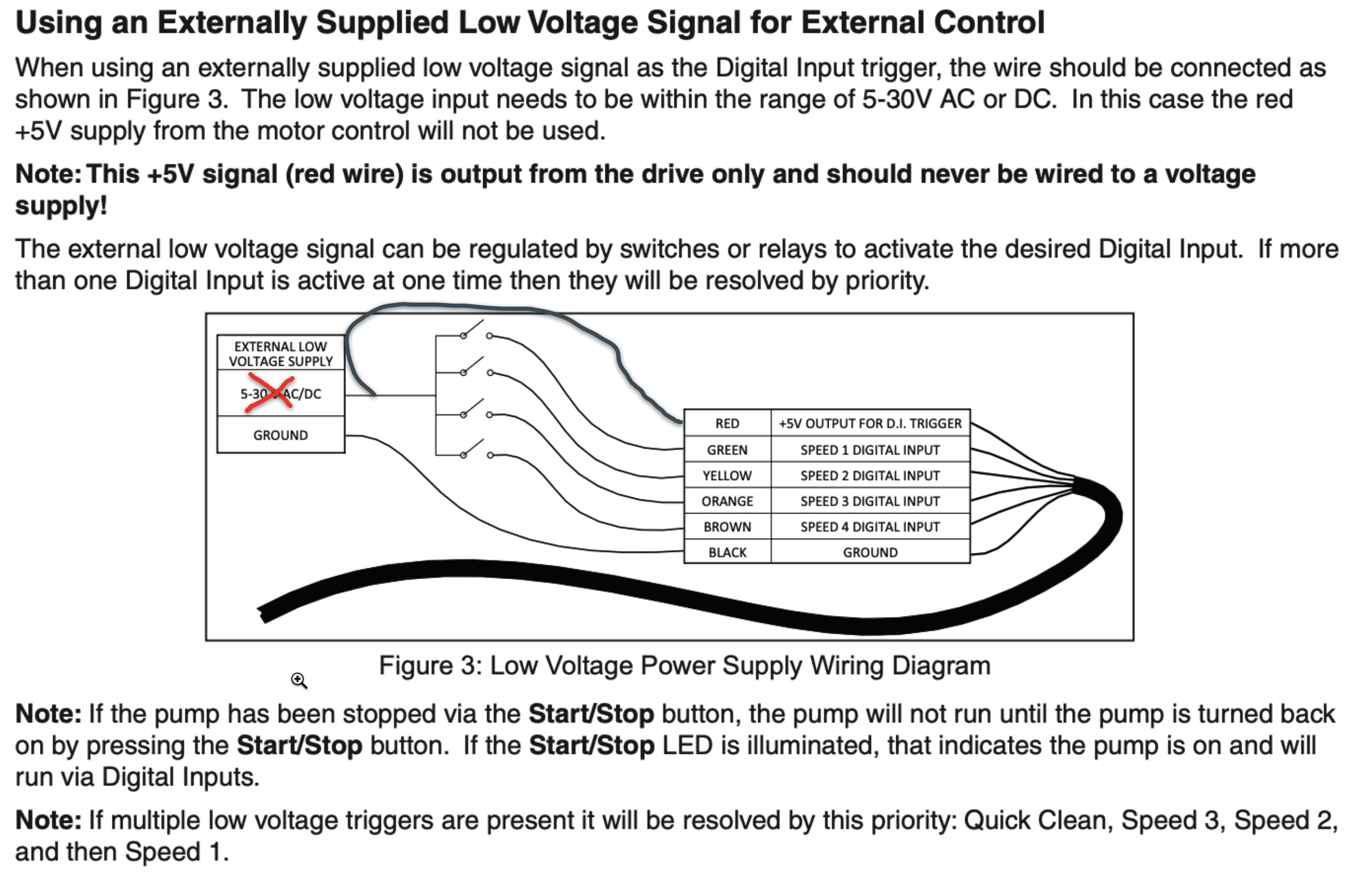
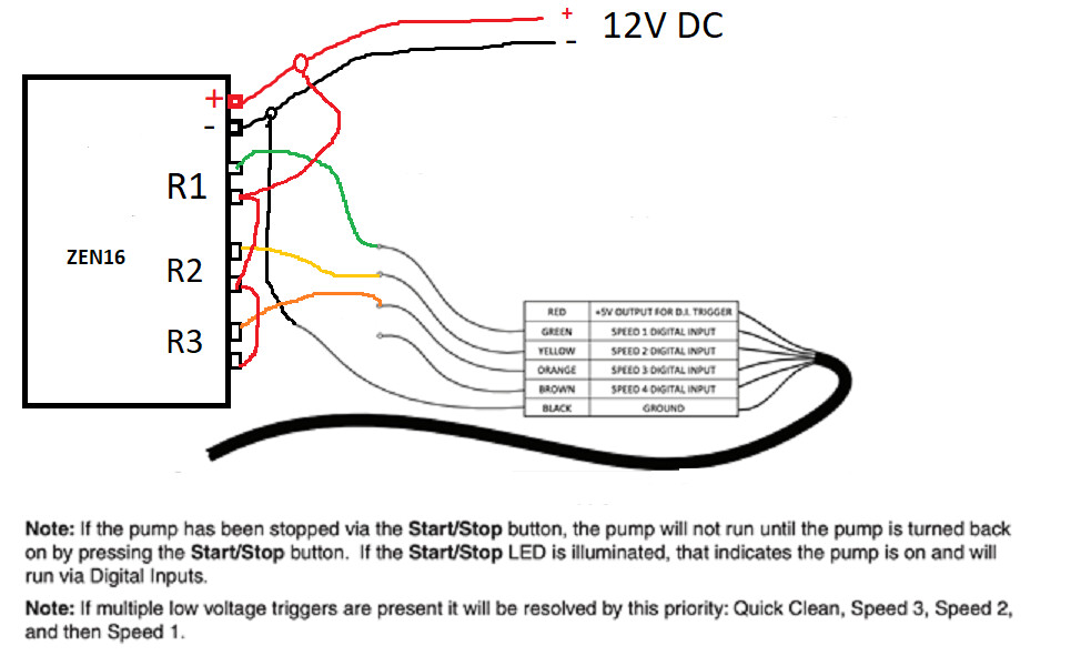
I had reached out the Zooz support over at thesmartesthouse.com prior to posting here. They were nice enough to send me this wiring diagram so I figured I'd share it.
NOTE: This diagram is if you don't want to use the 5v (red wire) coming from the pump communication cable and use the 12v power going to the ZEN16 multirelay from the wall adapter instead. Also, In my case I won't be using Speed 4 (Quick Clean) because I only have 3 relays to use. If you wanted to use Speed 1, 2 and 4 instead you could just substitute the orange wire for brown.
For anyone that is not aware, the "digital inputs" are really described as (5 to 30V) and (AC or DC) in the manual. So, this would certainly work.
Side note: I chose not to enable Control Mode Only. Should something fail - or I forget to change settings when we move - the pump will still operate for a modest number of hours each day.
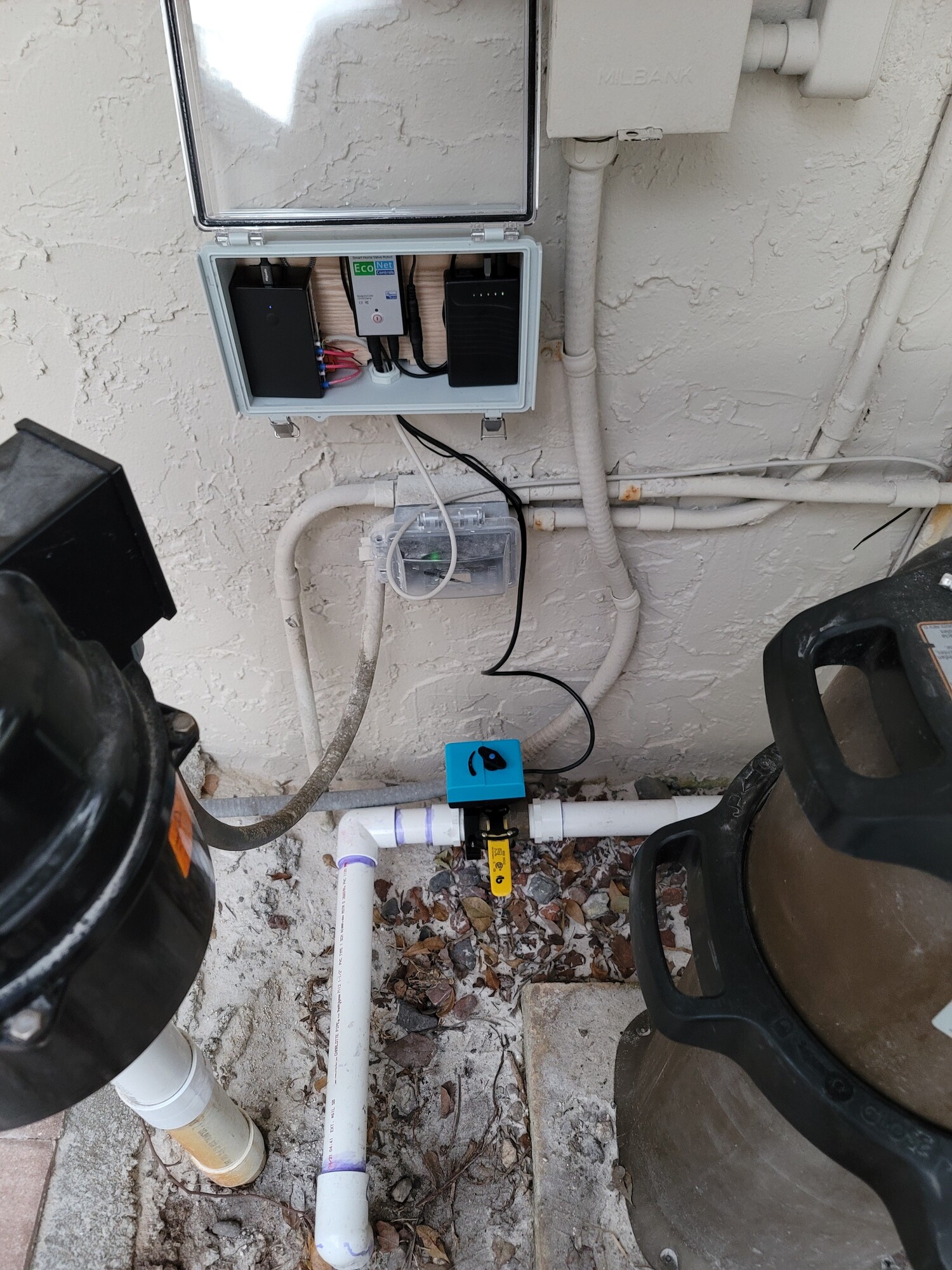
Sorry it took so long to respond. I actually couldn't find the communication cable anywhere due to supply chain issues. Anyway, Here is my setup. I actually did both the pool pump speed control as well as an smart valve for my pool drain line that goes out to the street for when my pool overflows from too much rain. Finally, I have both running off a talentcell battery backup.
I'm using Speed 1, Speed 2 and Quick Clean. And I'm using "One at a Time" app by bptworld to automate turning off the other two relays when one is turned on.