I got it working with the Zen17.
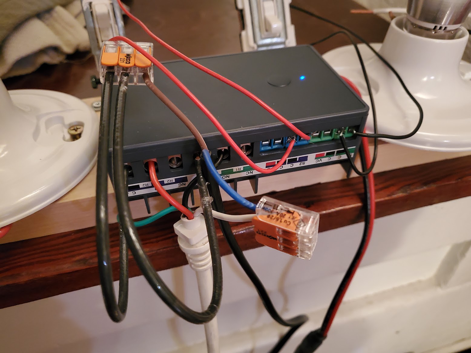
Built myself a test rig with lights so I could test out the circuits and relay programing without risking my screen.
Setup, two manual switches (will eventually be a single 3 position switch) to control the triggers on the Zen17.
This wiring only applies if the screen motor is setup to switch up/down on 110v circuits.
- The black wire from the screen's up motor is connected to Relay 1 (NO).
- The red wire from the screen's down motor is connected to Relay 2 (NO).
- Black Hot wire connects to C on R1 & R2.
- White connected to common.
- Ground connected to ground.
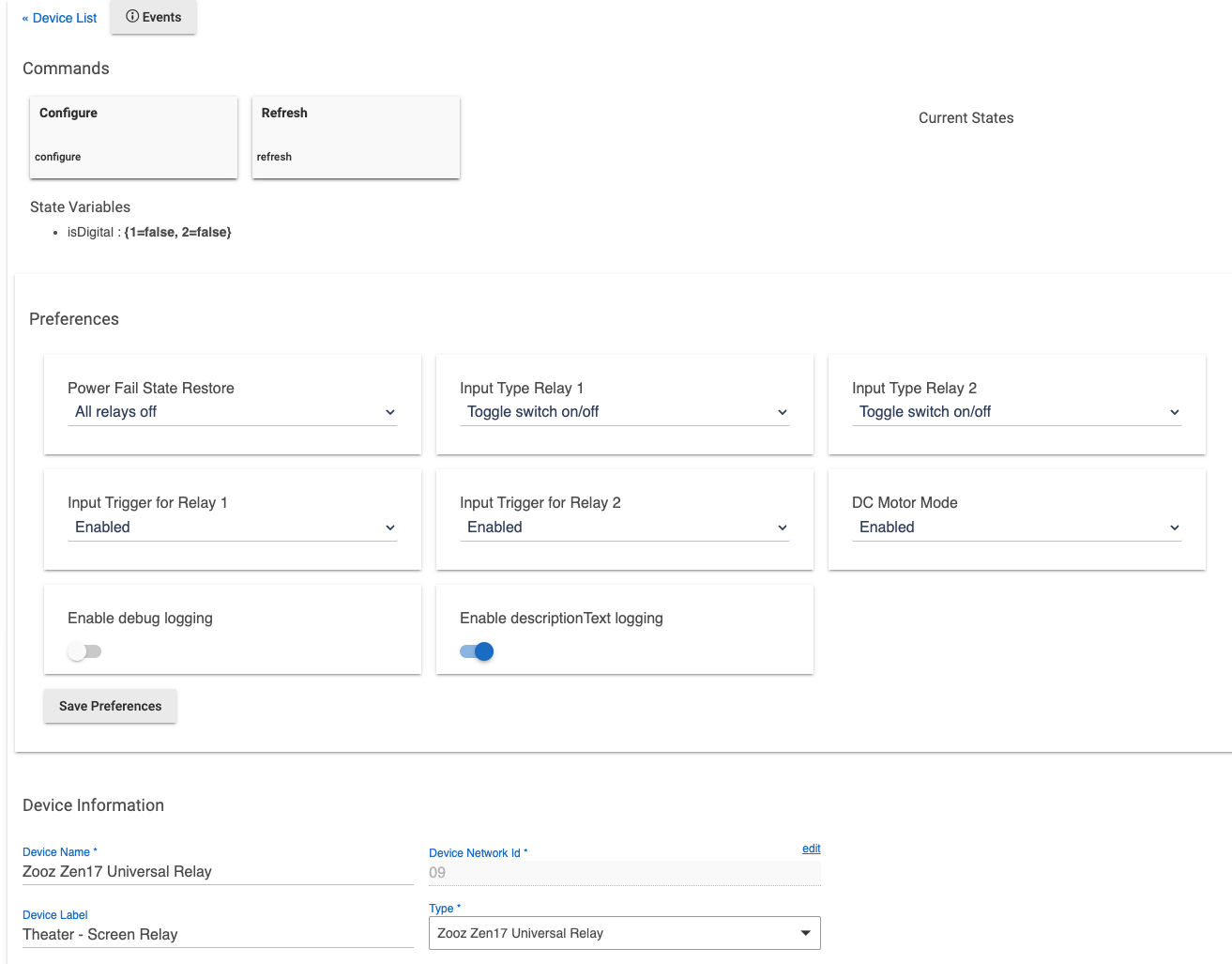
Using the advanced settings in the Zen17
- The Zen17 is set to "DC Motor Mode" which never allows both relays to be on at the same time. If one is turned on, it turns the other off first.
- Both relays are programed to turn off automatically after 20 seconds (the screen takes less than this time to fully open or fully close).
- If power failure, both relays start in the OFF state.
In Hubitat
- Both relays show up as two different switch devices. Simple switch buttons turn the relays on/off which controls the screen up/down. Turning both off stops the screen where its at.
ToDo: I need to put all of this in a housing and wire up a 3 position momentary switch for manual control.
Videos:


