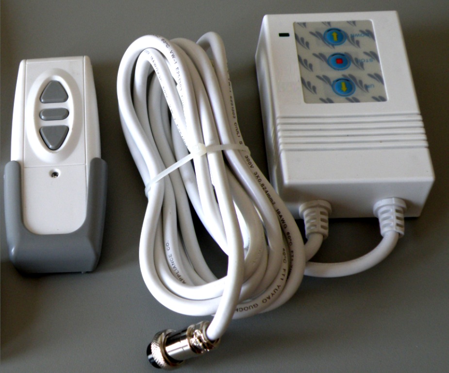
Anyone know a project / good way to add automation to a cheapo motorized projector screen? I've got one of those $120 ebay specials that all seem to come with this remote:
Mine is radio frequency (but they sell IR ones too). Something keeps tripping mine. I can't leave the thing plugged in because its will eventually get triggered and start moving on me. I'd like to add automation and by pass this RF thing all together. I'm sure I'll need something with relays, but was hoping there was a project already done out there.
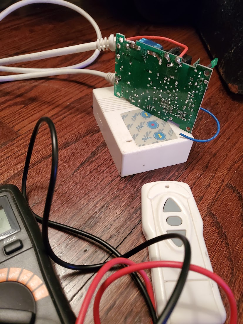
I've found a few posts dealing with specific higher end screens, but haven't found anything around hacking this controller. Which is odd because all the cheap screens come with this exact control box.
Its three one touch buttons, Up / Stop / Down and some how the screen knows when to stop on its own. Anyone know of an automation project that started with this screen controller?
I can't give specifics since I've never actually done this, but I've seen relays like this mentioned for this application before:
(I confess that I singled this one out because it's a new 700-series device, which I think is cool, but they have an older 500-series multirelay, too, and there are probably lots of older relays from other vendors that would work, too.)
There is one example for a DC up/down motor in the manual, which you can also find linked to above. I don't know if this would work for your setup, but hopefully this will give you some ideas if not.
So the ZOOZ Z-WAVE PLUS 700 SERIES UNIVERSAL RELAY ZEN17 WITH 2 NO & NC RELAYS (20A, 10A) device would replace this whole controler right? Then, if I wanted, I could have switches to manually control the up / down relays connected to the Zooz?
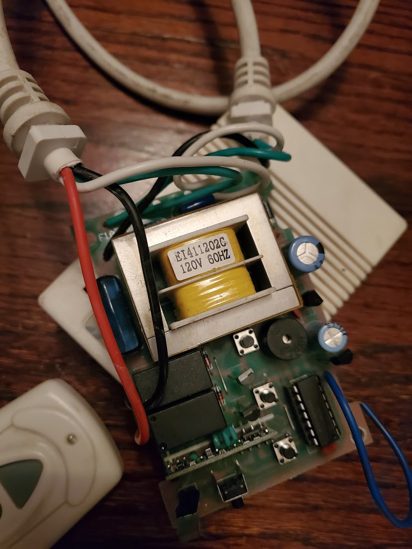
Could someone help me understand this electrically and how this would wire up? I measured the power coming out of the relays on the current controller and I'm seeing 12v on the meter. Guess I don't really understand that. There's only four wires going upto the screen motor:
Is it as simple as cutting the old controler out, connecting the RED and BLACK to the Zooz's two relays, and playing around with settings in Habitat? Or am I going to cause fires?
I think I over complicated this. I measured the screen again and I'm seeing 110v up to the motors when either relay is closed. So the relays on the OEM controller are 100% switching 110v after all. Which does make sense to me. The 12v measurement I got earlier was wrong and so the Zooz Zen17 will not work here. The Zen17 relays can only switch 12-24v. I need something that more akin to a light switch on / off.
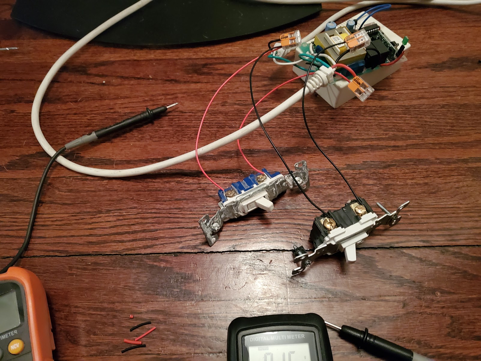
Did some testing tonight:
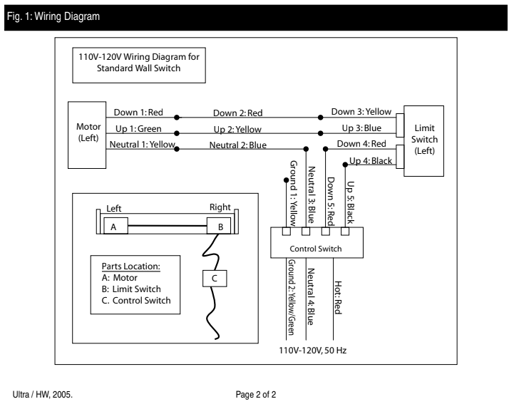
RED - 110v (NO) No Connectivity, Closing the switch contacts makes the screen move DOWN.
BLACK - 110v (NO) No Connectivity, Closing the switch contacts makes the screen move UP.
White - 110v Common
Green is connected to Ground
Learnings:
Closing either Red or Black makes the screen move.
The screen stops on its own after it reaches its max travel distance.
The Red or Black may stay closed after the screen has stopped moving, but really should be opened after a short while.
The key here though is I must make sure both relays are never closed at the same time. There's some advance programing settings in the device itself, but nothing for that specific protection. I'll order the Zooz52 and play around.
I just used a broadlink rm3 and set it to drop the screen when the amp turned on and lift it when the amp turned off. Has worked faultlessly for 2 years.
I believe that’s not correct. I have the ZEN16, which is an earlier variant of the ZEN17. The relays on both are dry contact relays that can easily switch 120 volts, and the relays differ only in the amperage ratings (10, 15, 20 amps). Mine is switching 120v AC just fine. It’s the separate inputs to which buttons, switches, etc., can be connected that are 12 to 24 volts, and the MultiRelays require a 12 to 24 power source OR a USB C power source.
In theory, if both relays closed then your screen will continuously going up and down until one of the relay open. This is due to the limit switches inside the "limit switch (left)" circuit.
There should be 2 micro switches in the limit switch circuit and they will always work opposite of each other. When the up is completed, the up micro switch opened and the close micro switch closed and waiting for the close voltage from the controller.
Took a look at the included paperwork again and yeah you're right... there is mention of running a 110v pool pump. Hmm...
Think I'm going to wire up some standard light bulbs to this and just play around. At least then I'm not risking blowing up the screen motors. It seems like the Zen17 does have a mode that won't allow both Relays active at the same time. Thats exactly the functionality I need.
The only oddness that I will warn you about is that, when updating the Zooz firmware (and they have been good about adding features with firmware updates), the device has to be re-paired, which can mess with your rules if you don’t substitute in a virtual device first. I have never been able to update firmware on my ZEN16 when it is paired with security, but it always updates fine when paired without security.
But my ZEN16 has worked flawlessly for well over a year.
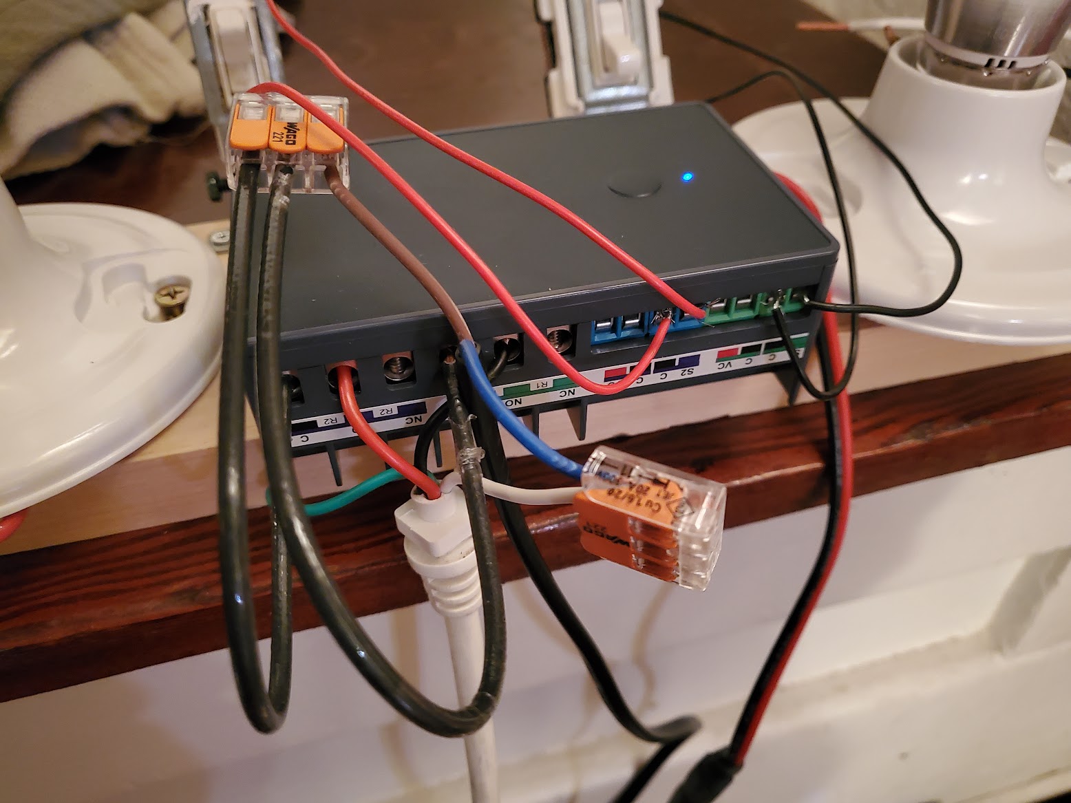
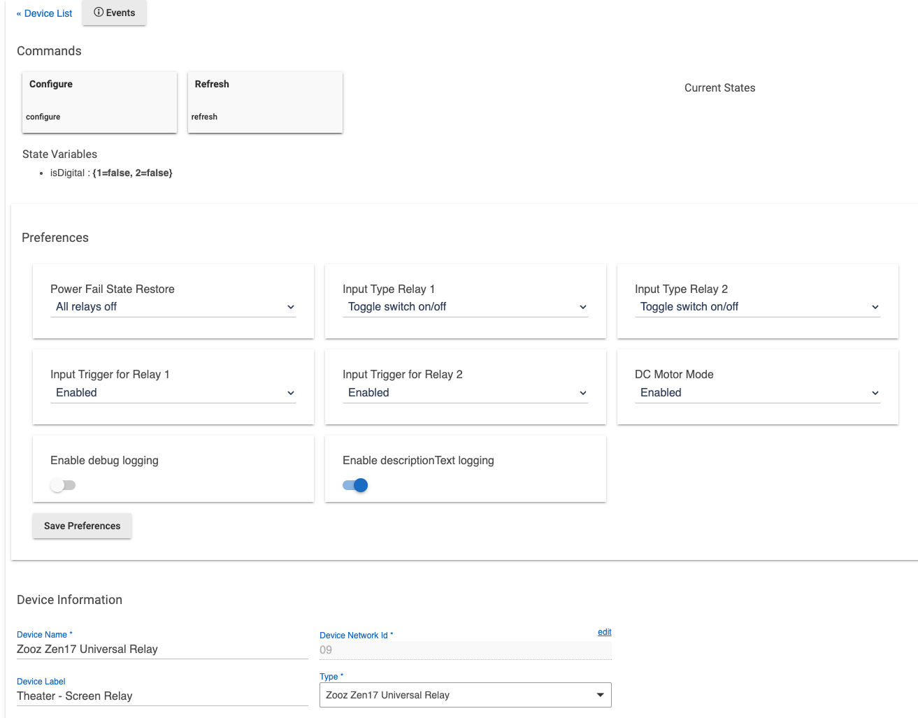
The Zen17 is set to "DC Motor Mode" which never allows both relays to be on at the same time. If one is turned on, it turns the other off first.
Both relays are programed to turn off automatically after 20 seconds (the screen takes less than this time to fully open or fully close).
If power failure, both relays start in the OFF state.
In Hubitat
Both relays show up as two different switch devices. Simple switch buttons turn the relays on/off which controls the screen up/down. Turning both off stops the screen where its at.
I thought that could be the case, but the screen made a weird sound when I tested it for a half second. I wasn't seeing both relays closed (on) together with the OEM controller, so I wanted to make sure I wasn't introducing a situation where both relays could be closed at the same time in the replacement.
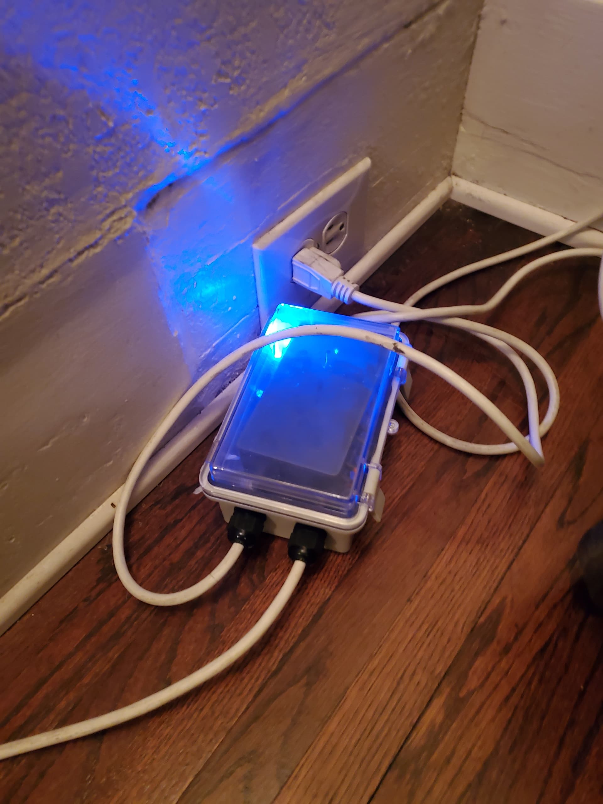
I crammed everything into a project box tonight. It's basically the same size as the old controller. I was going to add some manual momentary buttons for up and down. After second thought though, I'll realistically never use them. The whole point of this was remote control with Hubitat.
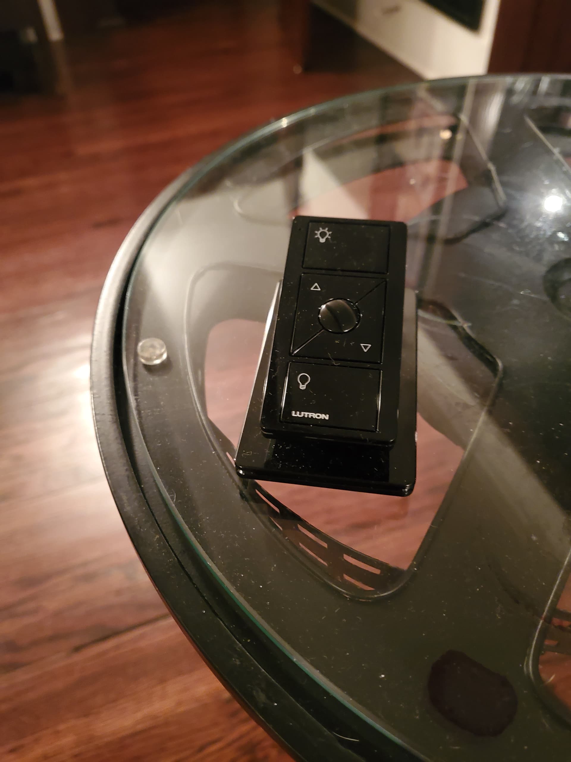
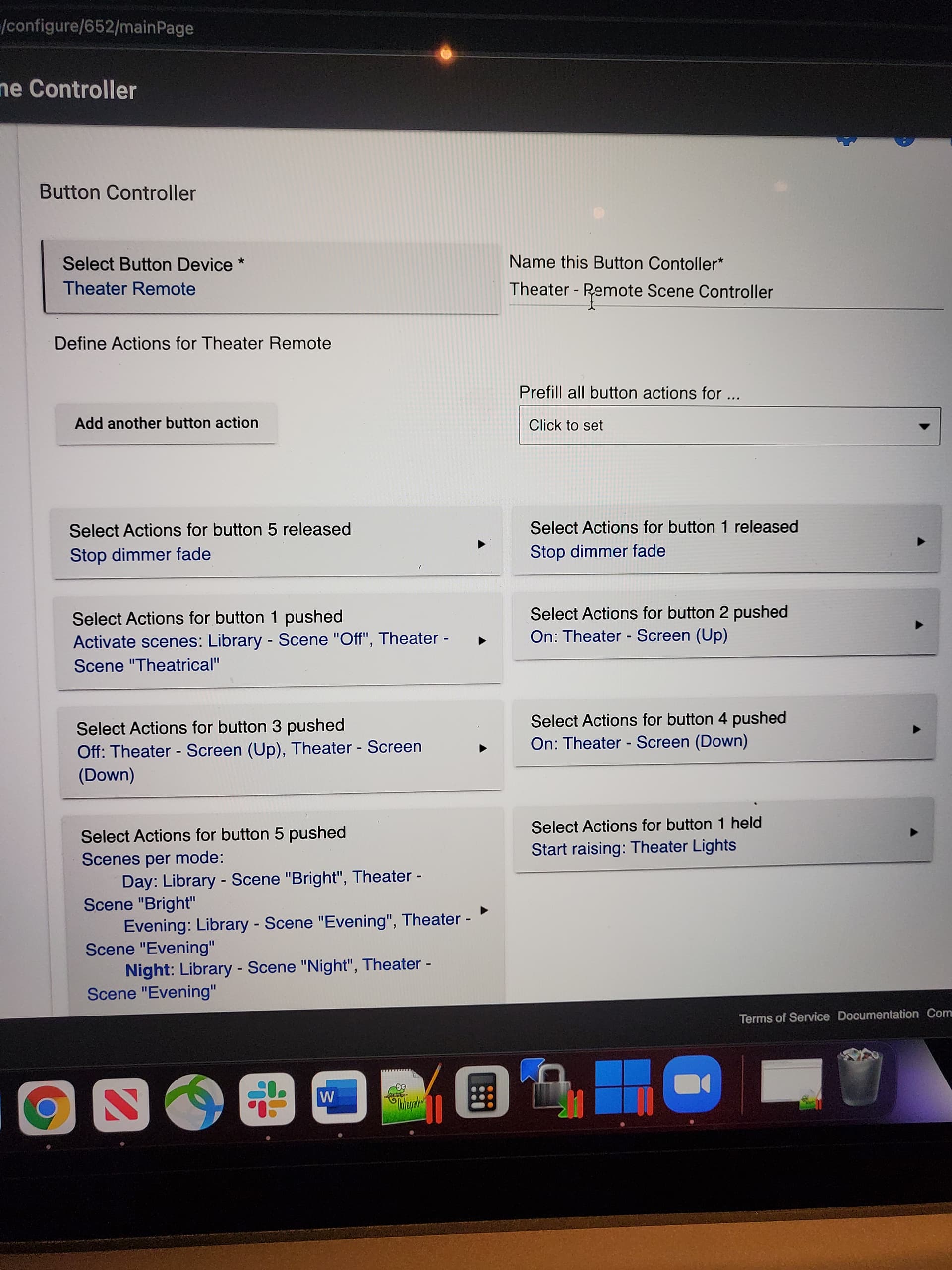
I've got the zen17's dual relays controlled by a Lutron Pico remote and programed UP (on 1), DOWN (on 2), STOP (off 1,off 2) as actions in the button controller.