I don't typically post things in forums. I lurk and search (and search and search and search) to get questions answered, rather than making new threads. That being said, I never really found a clean example of what I was trying to accomplish, so I figured I would post a topic for others to give input for improvements or allow future searchers to find this a bit faster.
So, as the title suggests, I have a smart switch running Tasmota (Treatlife 3-way, set up following a guide posted by digiblur rather than just using the template from blakadder; had to open it and serial flash the chip) and left the other end of the circuit dumb. The smart switch is installed in the first switch in the circuit (the switch receiving the "line" power, as opposed to the switch connected to the "load" wire). Mechanically, everything works exactly as it should as soon as things are wired up. When it gets complicated is controlling it with HE, any voice assistants, etc. This is because the 3-way switch uses 2 relays to allow the circuit to complete. Line power comes in, and then it "goes out" via relay 1 or relay 2. When the switch is added to HE via Tasmota Device Manager, it adds both relays as individual devices. Using the one relay ("Toggle 2" in my case), you can remotely turn the switch on and off. Great. But the problem is when the dumb switch is "on," this then turns the other relay on, which essentially reverses the relay you were just using to flip the switch remotely. No big deal, except that if you're using this "toggle 2" relay as your remote switch, and it is now reversed, HE will see it as on when the lights are physically off, and vice versa.

Tasmota Web UI showing both relay toggles
So, I scoured forums for solutions and couldn't really come up with anything that definitively worked, but found leads such as using a virtual switch. I use the virtual switch to send the "event on" and "event off" commands to Tasmota, which turns the lights on and off, regardless of relay positions. Ok, but what about when the dumb switch is used to turn the lights on, then the virtual switch still thinks the lights are off.
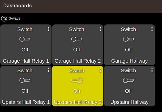
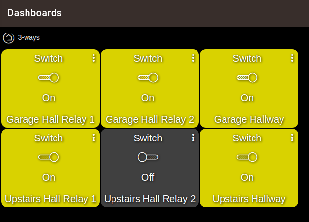
Depending on the position of the "dumb" switch, the relays that HE change
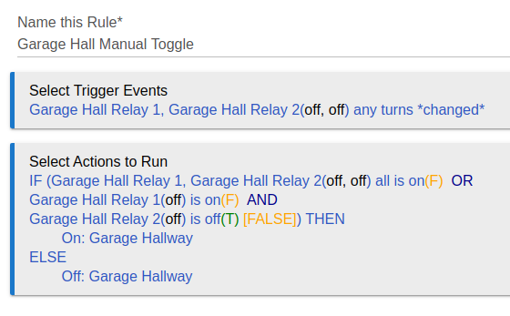
Thus I made a couple of rules to essentially monitor the positions of the relays and adjust the virtual switch position accordingly, but then only show the virtual switch on the dashboard for remote control. I use one rule to send the commands upon a change in the virtual switch position, and another rule to position the virtual switch upon a change in the dumb switch positions.
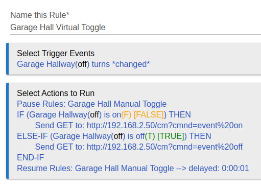
The pause at the beginning of the virtual toggle stops the "manual rule" from seeing the change in relay positions and sending another command to change the lights again.
I use a 1-second delay and a 2-second delay for another light that seems a bit slower to respond to changes.
This has been working for me thus far (about 12 hours of playing with it). I opened up the virtual switch to the voice assistants and that seems to be working out as well. Another side note, one of my circuits also includes a 4-way "dumb" switch between the smart switch and the other 3-way dumb switch, that ultimately doesn't change anything as far as the smart switch is concerned, so if somebody has that setup, this seems to be working for that as well.
Like I said at the outset, if anybody sees this and knows of a way to improve it, I'm all ears. Hopefully this will help somebody that is trying to accomplish the same thing and struggling to find a definitive solution.


