I would assume you have a single two wire going to the switch? Looks like the white is wired to the yellow S which is good. On the same wire is the black tied in with the black hot bundle? This would then send 110v to S when you turn it on.
I wired up a 3way with the same setup, works great.
Blue IN should be with the black hots, and red OUT goes to the load (light)
I think I have everything wired correctly except that the white of the two wires going to the switch is no longer paired together with black like before. I was thinking that was what was missing. I was thinking maybe the relay would handle that.
Edit: Re-reading, I think I do in fact have everything wired correctly. For the single two wires originally going to the switch, the white is with S1 and the black is with the black/blue bundle. Turning the relay off from the switch turns the relay off, but turning the switch on does not turn relay back on. I will try by having a separate line going from the hot black bundle to the s1/white bundle, but I don’t think that’s necessary?
No that would not work, sounds like you have it right.
What FW version is stamped on the back and what FW is it on now?
Also, what setting do you have the switch set to? You probably want it on the default On/Off setting.
How long is the wire run to the switch, you may some induced voltage which effects the original hardware marked FW 1.10 on the back.
I upgraded to FW 1.40, but still need to do the suggested power cycle. Hubitat reports 1.40 as the firmware now though. It’s probably no more than 15ft from the fixture to the switch.
Need to know what FW is printed on the device. There was a hardware fix which is printed FW 1.30 on the device. Not sure what you mean by "still need to do the suggested power cycle".
The 1.10 HW is the original, but it should work fine with your run, I think over 15ft is pushing it. But since you can turn it off and not back on that is more indicative of a wiring problem I think. I think it mostly only was a problem with 3-ways also.
I only see the IN and OUT tied to one other wire which I assume is the hot feed. Where is the switch leg getting its hot power? The switch leg would have two wires, the white you are using as the return, the black would be the feed, the black should be connected to constant power. Both white and black should be connected to opposite mounts on the switch itself (same as it should have been prior).
Also where is the light, in another box? Light should have Neutral tied into the Neutral bundle, and hot should be connected to the RED/OUT
It almost looks like the black/red combo and the white/yellow are both the same wire, and I don't see any other wires. So still confusing on your wiring.
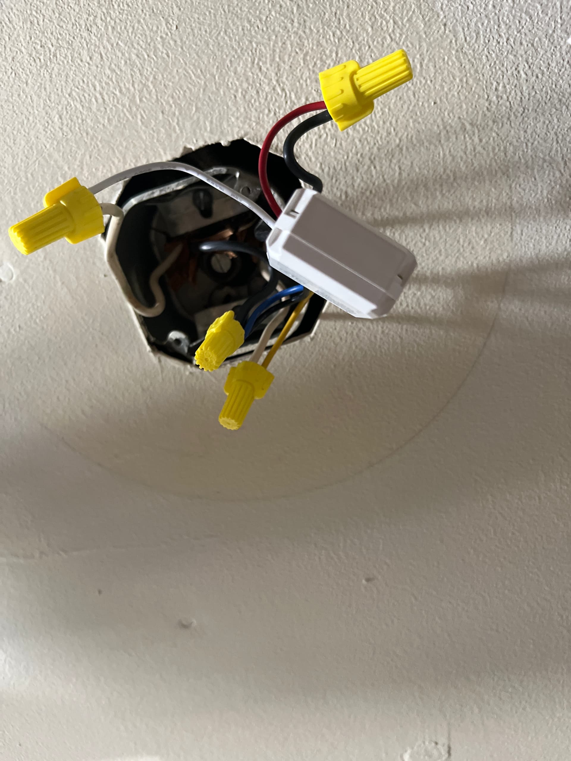
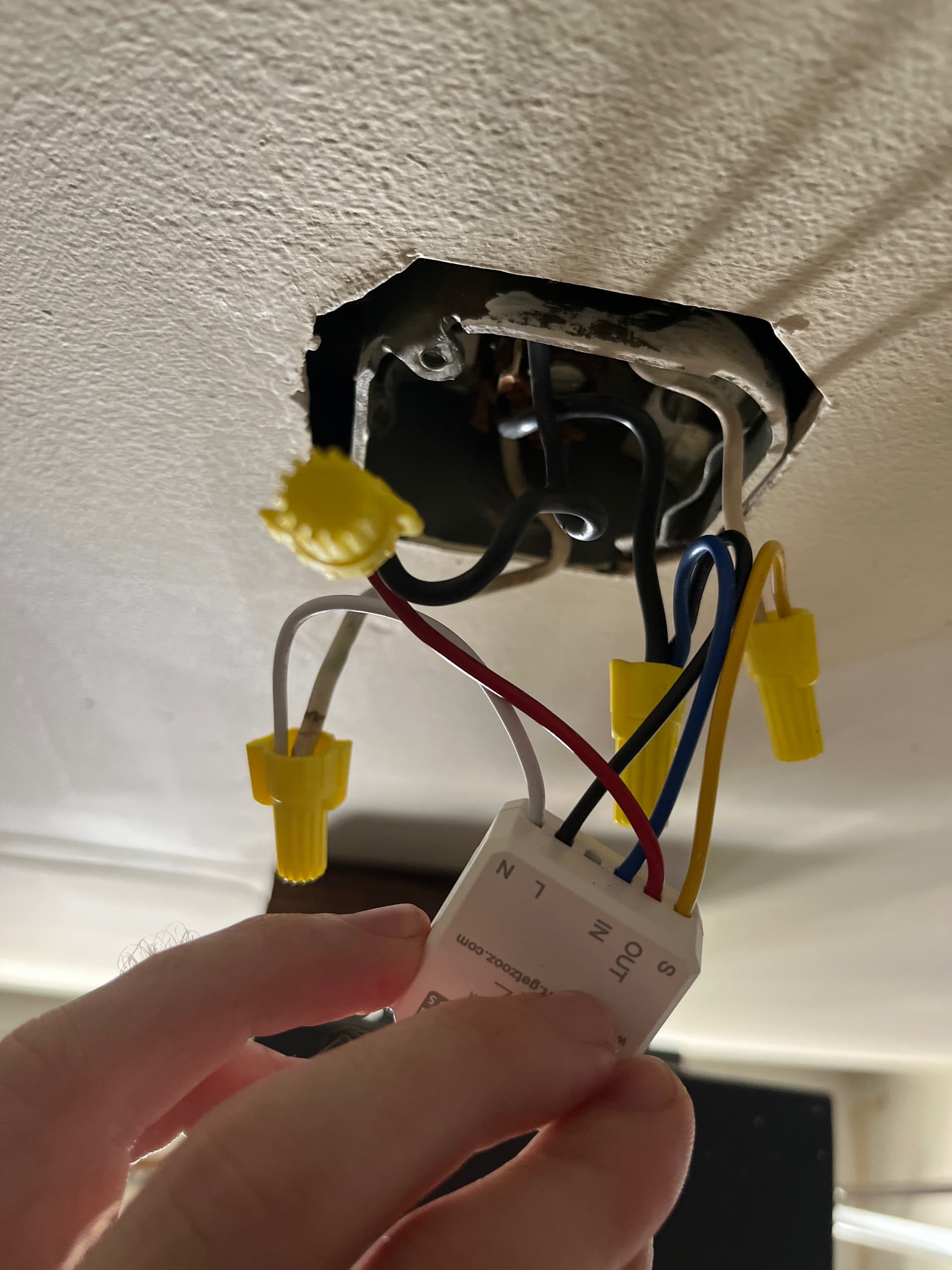
I had removed the light just to make sure power was properly getting to the relay. Here’s some more photos of the wiring. I’m no electrician, but maybe there’s the potential I swapped the black that was going to the light fixture with the black of the black/white pair.
I cant really see where the RED/Yellow eventually go in those pics.
Where are you connecting the light fixture in there? If you have it removed the Red should be capped with nothing on it.
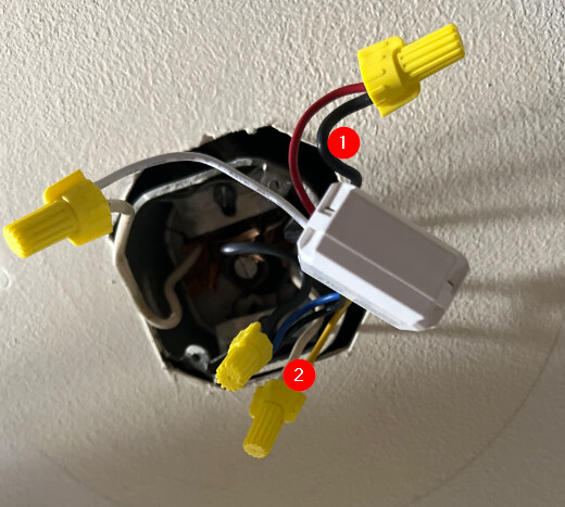
If 1 and 2 as I marked are both going to the wall switch which is what I suspect, that is the problem.
2 would be correct in that case, but 1 would need to go in the hot feed bundle, and the red goes to the hot on the light fixture.
Yes I was just typing as such, now it should work, white from light goes to neutrals, and black from light goes to red. Not sure how the relay even powered up if you had the hot feed connected to the red, the light would have also been always on with no way to turn it off. I suspect it was wired as I stated above, but now you have fixed it.
Interesting! Just ran across this topic.
I'm thinking of making up a table lamp rotary switch add on. Maybe some hot melt glue across the side of the bulb socket.
What do you all think?
A true smart home should have controls that a stranger can turn a light on/off w/o using an automation, like an in wall light switch.
How does a person control a table lamp, using the same philosophy? How about strapping this relay across the lamps rotating switch?
Think it would work?
Not really "across" but after it (between switch and socket), wired up the same as you would with a light switch. Yes it should work. You would need to have a large hollow area in the lamp for the device and wiring though. If the rotary switch was up in the stem by the socket it may be a challenge to get the wiring back down then up to the socket again, but maybe not, I have never taken a lamp apart.
Correct, thats what I was saying. You do also have to wire a hot feed and neutral to the ZEN so its still a lot of connections to make if you have a tight space.