First of all; I live in Norway and have a balanced ventilation (hvac?) system named Exvent. It's an in wall ventilation system which provides ventilation to all rooms in my apartment. The model I have is about 10 years old, came with the apartment when I bought it last year and just not old enough to justify replacing it but old enough to be out of the product line of the producer.
Exvent seems to initially be a Swedish system but later bought by a German company. So all documentation I have on the system is in Swedish.
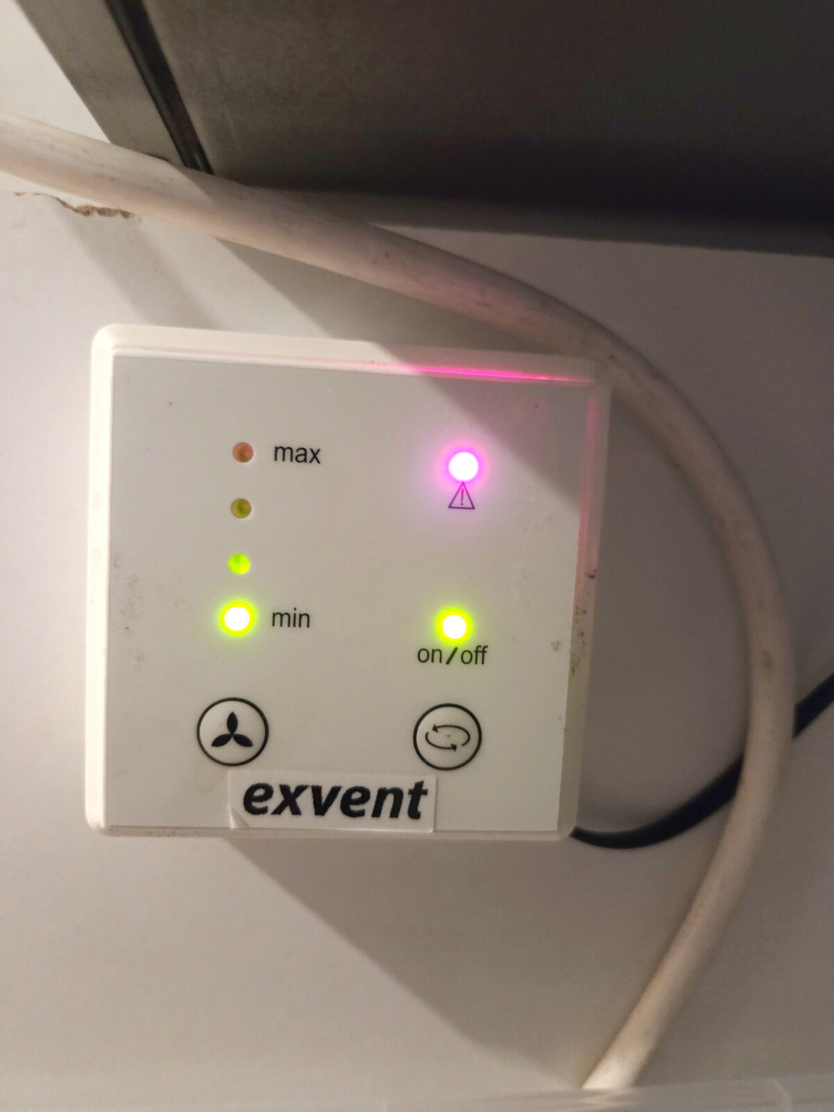
The system has a "manual" control box which has an on / off button and the possibility to set the ventilation on 3 different speeds. It looks like this:
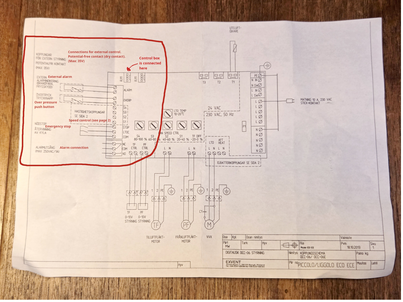
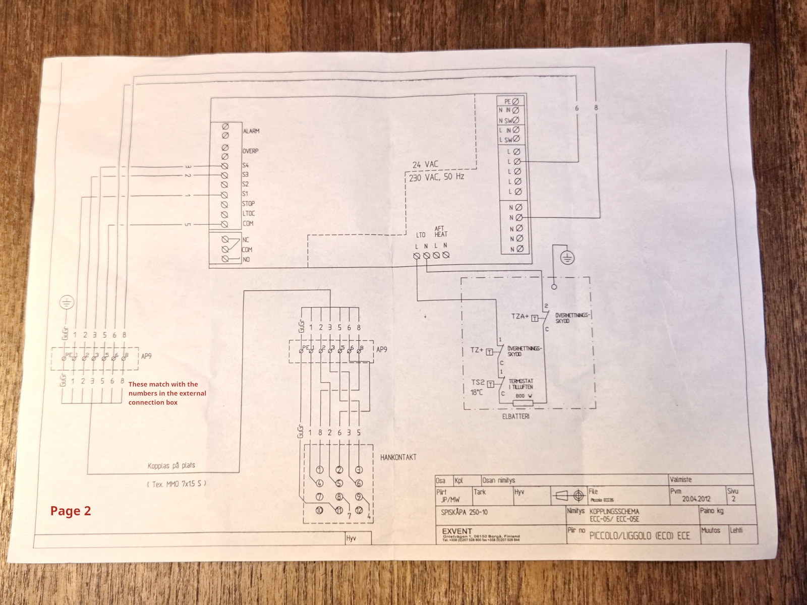
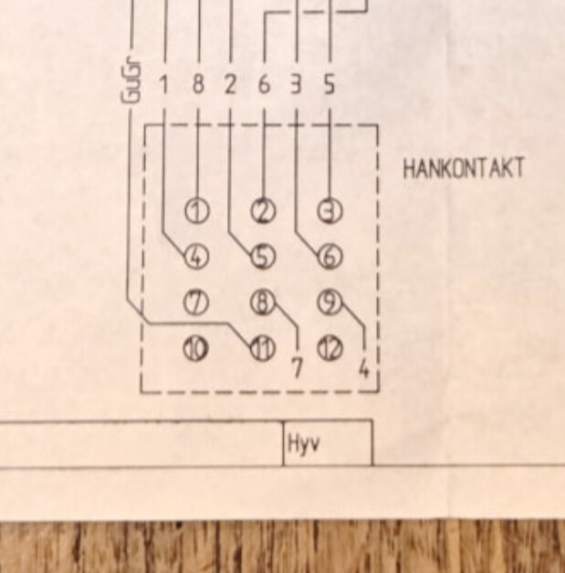
I also have the electronic drawings for the mother board of the ventilation which outlines the external connections which can be connected to the system. It consists of two pages and I've outlined and translated the parts I think are most important.
What I want to do is to be able to hook this up to my Hubitat, preferably with a z-wave based device (preferably with a 800 series chip based device and it must be available in Europe), so I can regulate the speed of the fan of this. I would like to be able to utilize all 3 speeds and also turn it on / off and maybe even get error warnings from the system.
But I have no clue what device I need to control this one. Any advice or ideas?
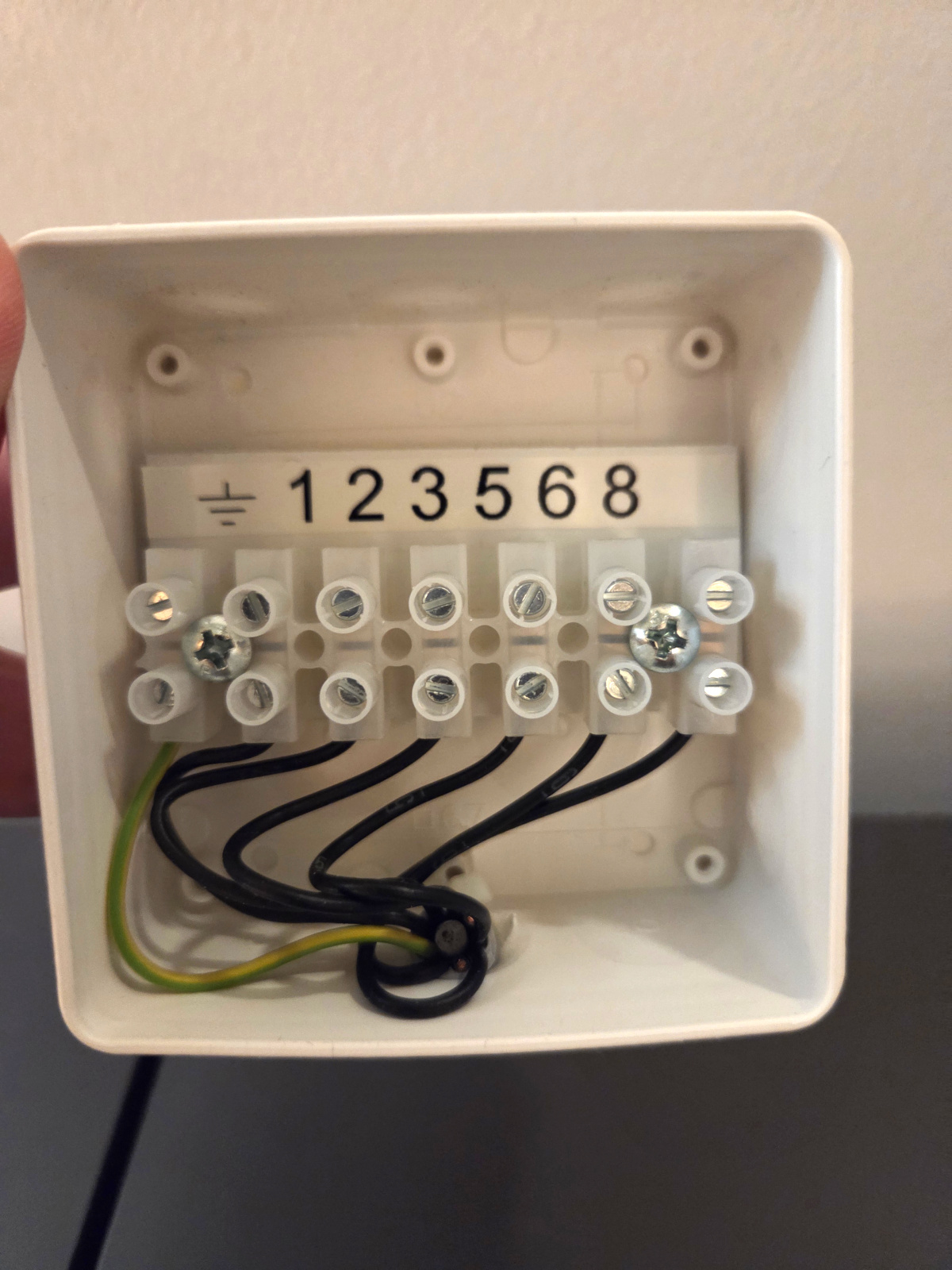
Can I utilize the contacts on in the external box? I do also think the system can communicate with modbus (which I have little knowledge of).
PS 1: I am super fine writing a custom driver to any device if needed btw.
PS 2: Yes, it's possible to buy a smarthouse connector for this system, but it's a proprietary system with its own app and does not provide any protocols compatible with Hubitat. Yeah, its stupid.
one terminate terminal 5 (com) and 1 (S1), the fan runs at speed 1
one terminate terminal 5 (com) and 2 (S3), the fan runs at speed 2
one terminate terminal 5 (com) and 3 (S4), the fan runs at speed 3
If that is the case, then I think I can ex use the Shelly Pro 3 which is a 3-channel relay and write a custom "fan controller" driver which make sure only one of the 3 channels are terminated at the time (not controlling each channel independently).
Does this unit actively heat or cool the air? If not, it appears this unit is what we in the states call an ERV (Energy Recovery Ventilator).
If an ERV, many of them are not really off when off - rather they are in standby mode with the fan off - ie the unit itself has power (so not off as in no power to it) but the fan is off so it seems like the unit is off. You need to figure out what voltage the controls use to determine how to control it with Hubitat.
FWIW, I installed some Zooz relays to control my Panasonic ERV.
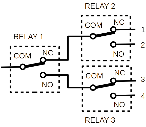
I would advise against using a multi-output relay for such control unless you are certain that there are will be NO damage if multiple relay outputs are enabled at the same time. I had a similar problem with controlling a two speed fan where the instruction leaflet warned against applying power to the two inputs simultaneously. You should be able to achieve a selection of only one of the connections to the common by using several dry contact changeover relays. I am not sure of z-wave options but I have come across of several such zigbee relays, an unbranded one from asia and the Sonoff MINI-ZBD. Both are mains powered, although the Sonoff one also has the option of 12-48V DC power, and a single set of dry contact (i.e. isolated from the power supply be it mains or low voltage DC) change over contacts COM/NO/NC = common/normally open/normally closed). They both also have inputs to allow triggering a change of state via switch inputs. Basic details of the Sonoff device can be found here SONOFF MINI Dry Zigbee Dry Contact Smart Switch | MINI-ZBD with more technical details at MINI-ZBD-SONOFF Help Center . To connect the common to one of four inputs you would need 3 such relays, the NC and NO outputs of the first relay being connected to the COM input of the second and third relays respectively and then each of their NO and NC outputs connected to one of each of the four inputs.
With all relays off the Com input of Relay 1 is connected to output 1. Obviously some "programming" is required to achieve the 4 possible outputs but the physical design of the relays prevents two outputs being activated at the same time.
With the system on, but nothing connected to the "external connection box", it may be worth checking what the voltage is of lines 1, 2 & 3 with respect to line 5 (which appears to be common connection) and although the circuit diagrams imply that this part of the circuit operates at 24V AC I would start with a meter set to a voltage range for mains voltage just to be on the safe side.