Hopefully they didn't just splice it and cover the box... that's a definite no-no.
The company that did it was well known and had a great reputation.
But the messy wiring in the box does alarm me.
This project is complete.
I capped the red wire at both locations. At the primary location, the Sonoff is connected to the black and white wires. This switch controls the light. At the other location, the white and black wires are connected, making this a two way circuit.
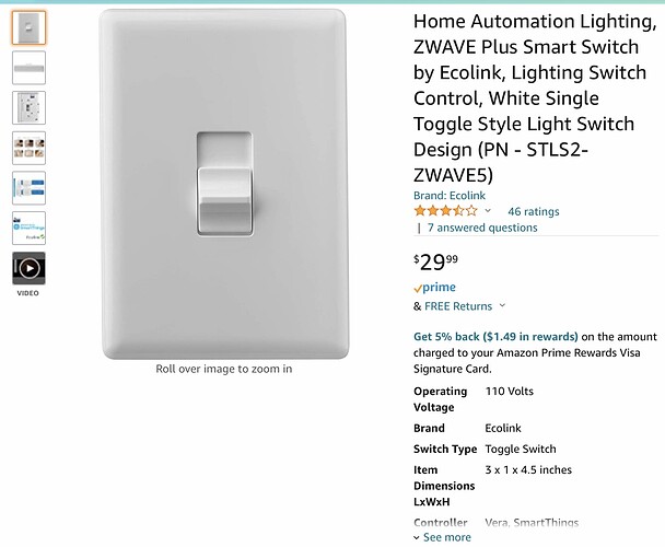
I had an Ecolink Z-Wave Plus switch in a drawer from my ST days. I gutted it so the motorized part doesn’t work. Just needed the up and down slide switch function. It paired with no security.
Note the operating voltage. This is powered by 2 AA batteries.
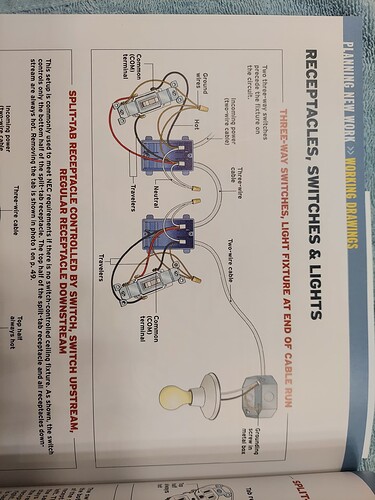
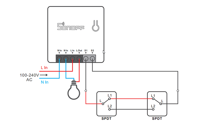
If my three way switches are wired as the second pictures shows: incoming power into one switch box and wire to the light into the other switch box, is it possible to automate this setup using a ZBMINI, or ZBMINI-L? I think with the MINI I determined I could not because I did not have access to power and the light/load in the same box. What I right about that? With the L the diagram provided by Sonoff that is all over this thread seems to show I need to have access to both "C" wires the power and the light.
I guess the short question is, how does automate this three-way setup (second picture above) using a zbmini or zbmini-l?
Thanks.
Yes, that one. Is there a way with the zbmini-l ?
Is there a way to use a ZBMINI-L?
None that i can think of... sorry.
Had a similar issue with a three way circuit in the bathroom. Wanted to automate the light but my home has no neutrals.
I ended up leaving the red wire (traveler) capped at both ends. One switch location has a ZBMINI-L and the other location has the white and black connected together, making this a simple two way circuit. Then at the dumb location I installed an Ecolink Z-Wave motorized switch. This is not connected to my house wiring. When the switch is turned on or off, HE turns the ZBMINI-L on or off.
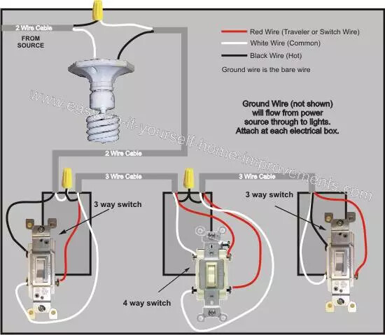
Whenever I need to do a 3-way switch I always refer to this simple diagram.
Power at one end, load at the other.

But not everyone wires 3 and 4 way circuits the same.
That was one benefit about working on cars. When you pulled a Buick Enclave into your stall, you knew what to expect when you open the hood, unless an ‘engineer’ has ‘improved’ something.
With a home, who knows how things are wired. Just like plumbing.
My 2 way switches are connected the same way, can’t figure out how to connect ZBmini to it.
Hi, did you fix the problem? I just install this switch in one room in a normal 3 way wall switch, at first works great, but when a turn off an on from de wall switch the zigbee switch loses the energy, i have turn on and of the other wall switch to get electricity on to the zigbee switch 
That is exactly how my circuit works. That is why I connected the black and white wires together at one switch location. The red traveler wire is capped on both ends. Then I used an Ecolink switch to trigger the other switch.
I essentially converted the three way circuit to a regular circuit and added a battery powered smart switch at the location with the two wires connected.
Hello Tom, is there a way that you can summarize your solution?
I am so interested and trying to use the Sonoff mini. no neutral in a 3-way configuration.
Please !!!!!!! ....... My kids keep leaving the garage lights on ll the time, but there is no neutral. My garage have 3 switches to turn the lights on/off and I can not wait to automate them.
If you can share your knowledge it will be great for a few of us that are looking for that option. Diagrams and Pictures will help for us that are less technical.
Thanks
My circuit only had two switches. I connected the black and white wires together at one location, capping the red wire. At the other location I capped the red wire also. The black and white wires connect to the Sonoff Mini. I used a momentary Zooz Decora rocker switch at that location. For the location where the black and white were connected, I used a battery operated Z-Wave switch. When that switch is turned on, Hubitat turns on the Sonoff.
Since you have three switch locations, these instructions might not work.
There's always a neutral somewhere... if not in the switch box then it will will be in the ceiling boxes.
They'll also help for the people trying to help. Any chance you can ID the wires in each box and figure out how the circuit is wired?
I have opened many boxes in my home. There are no neutrals. It might be code now, but not in 1969 when my home was built.
So besides a "hot" conductor, what other wire is in your boxes? The current must make a full circuit back to the panel. This requires two conductors, commonly called the hot and neutral.
EDIT: i want to add that I'm not suggesting that every box has a neutral, but there must be at least one in each circuit somewhere. Usually a neutral exists in at least the first box on the circuit and at each load. That's why a diagram can be helpful in identifying how a circuit is wired and what options are available for automation.
You probably have a neutral in the fixture box. You also have a 4-way because you have 3 switches.
There is a diagram in the Sonoff manual that looks like it would apply for installing it in the fixture with the neutral.
They show only a 3-way switch (2 switches) setup but I think the same would apply for a 4-way (3+ switches)? You would keep your existing switches, probably do not even need to re-wire them. I found an example of a hot loop 4-way setup where the source wire is in the fixture. Although you may have white wires in this diagram they are connected to the hot in the fixture box and just create a loop back to the light.

This will be fairly complicated, you will need to pull out the light fixtures to find where the hot feed is located with the neutral. You will also need to figure out the two wires going to the switch loop, possibly one white and one black but both would be connected to hot if yours is wired as you describe.


