Success! 0-10 Volt Control of AC Infinity (or any EC fan motor) using Leviton ZS057-D0Z Zigbee Dimmer or Zooz Zen54 zWave 0-10V dimmer

I've been looking for a solution to automate power and fan speed on a few AC Infinity EC fan motors and have been stumped for two reasons:

  1. AC infinity does not "support" any other control of their devices so did not provide any information.

  2. Qubino (which sells a 0-10V dimmer device) is only supported for EU zWave.

EDIT: Zooz now sells the ZEN53 and ZEN54 which support 0-10V DC and 0-10V AC control with CAD/US zWave frequency. Details in thread posts beginning March 2023. You want the Zen54 for 0-10V control of EC fans.

Enter the Leviton ZS057-D0Z which is sold as part of the "Illumina RF" wireless control line of Leviton controls. It's a 0-10V dimmer that is connected and installed as a standard 120V light switch. It has two extra wire leads for the 0-10V device to be controlled. What's not obvious, or listed anywhere, is that this device is actually a standard Zigbee device and can be paired to Hubitat (and I'm sure SmartThings). I purchased two of them from Aartech here in Canada...a great vendor to deal with for automation bits: ZS057-D0Z Leviton Lumina RF Decora, 0-10V Wall Dimmer, 2.4GHz - Aartech Canada

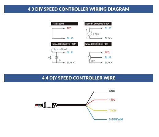
Terrabloom (I use one of their 6" EC fans for my kitchen exhaust fan, automated to the induction cook top) answered my queries with a basic "if it's designed to work as a 0-10V dimmer, it will work with their fans. Terrabloom does have a video on creating your own DIY speed control for their EC fans, but you'd be doing a custom Arduino board to do it. They do include a cable with their EC fans for DIY control, so you'd just need to connect two wires from that harness to do it if using the Leviton dimmer:

Leviton violet wire connects to Terrabloom blue
Leviton grey wire connects to Terrabloom black
The other Terrabloom wires are left disconnected (red and yellow)

terrabloom DIY

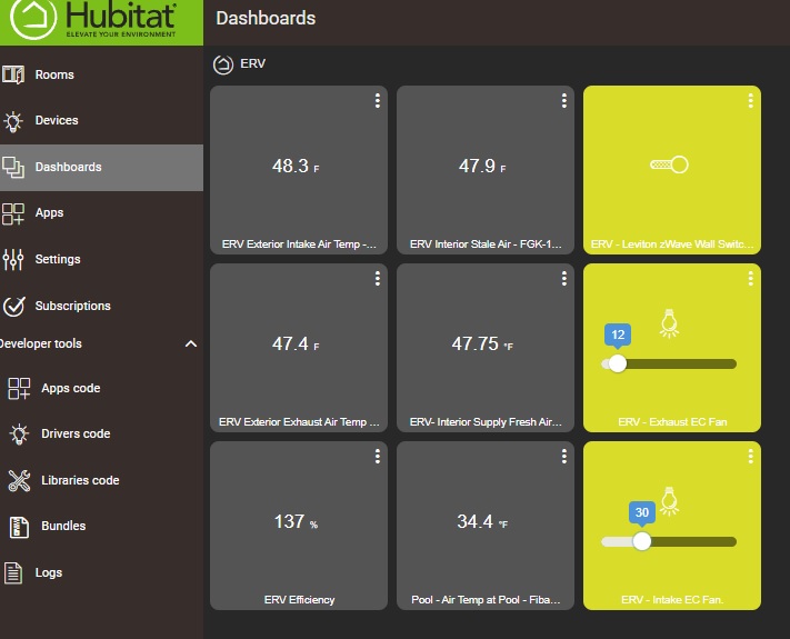
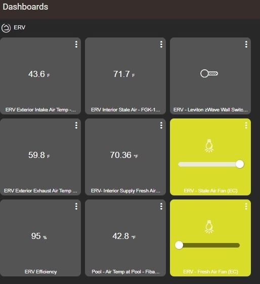
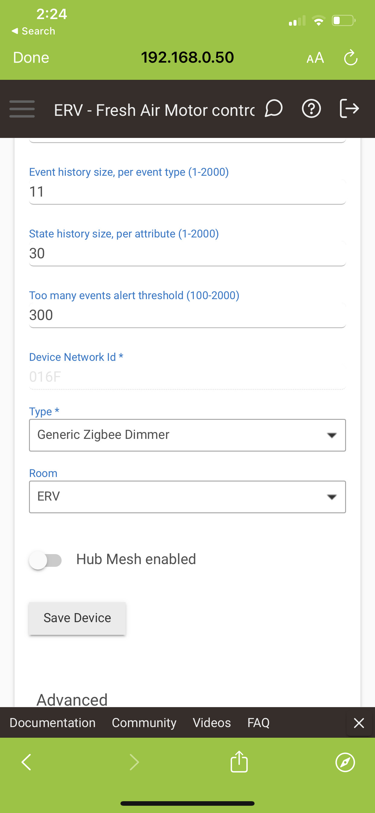
You just need to set the driver to "Generic Zigbee Dimmer" after inclusion to Hubitat.

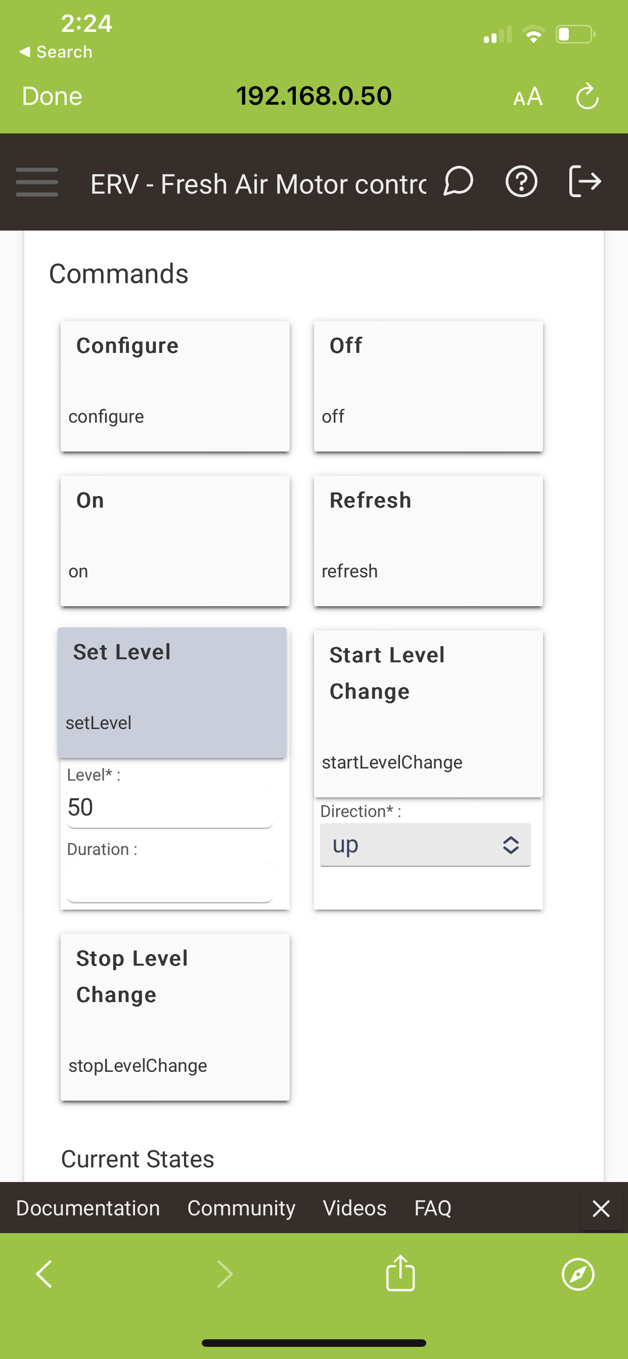
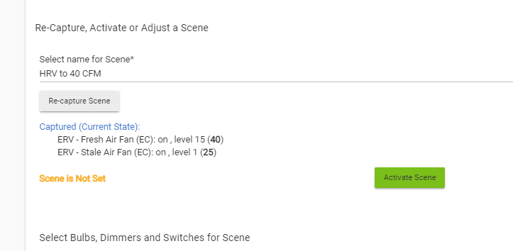
Setting the level for the device in Hubitat then controls motor speed..and the setting is also reflected via the green LEDs on the Leviton Dimmer.

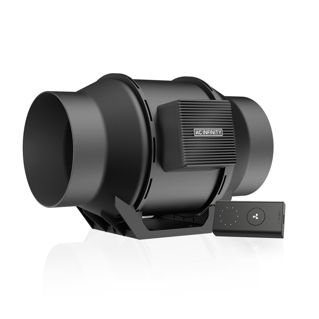
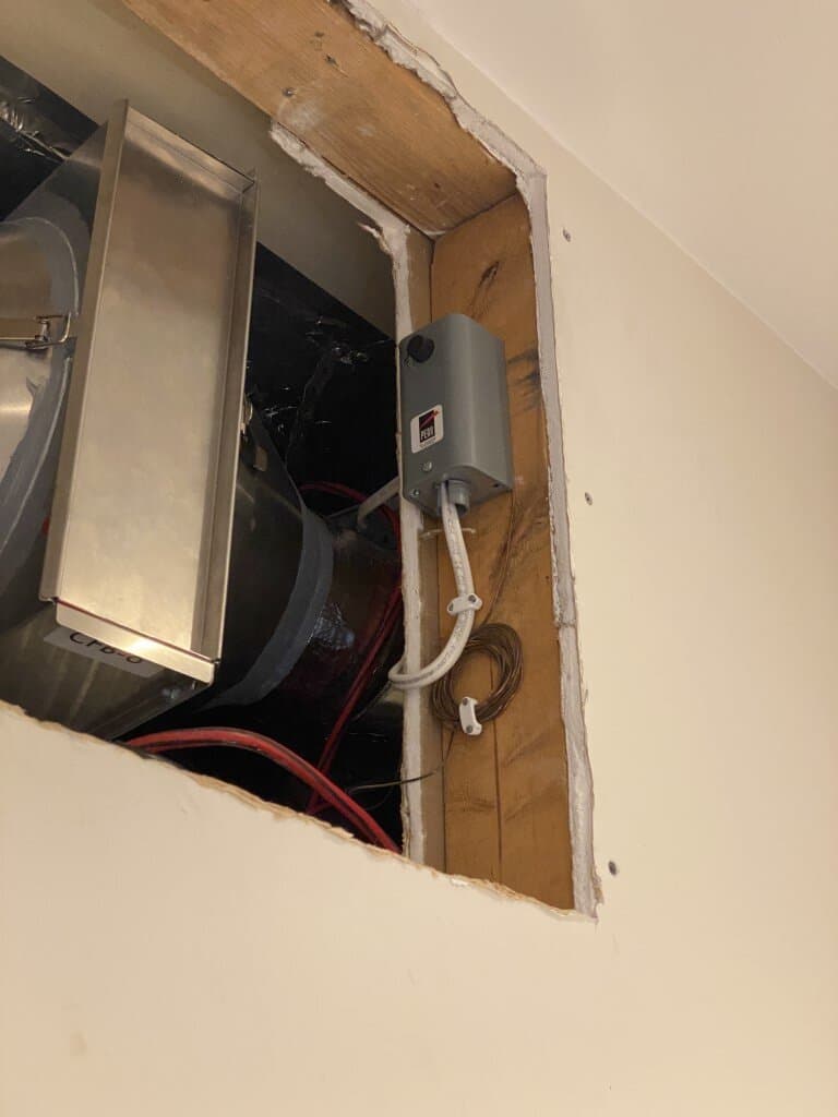
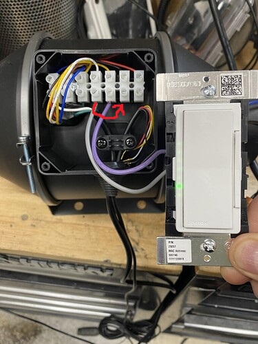
For AC Infinity fans like the Cloudline T6 fan fan pictured here, the connections are pretty simple.

Remove the 4 wires that connect to the AC Infinity remote control, and connect the Levition as below. You can check with a multimeter with the standard controller first to make sure you have the correct wires.

The AC Infinity wire colours (controller is disconnected in this photo) correspond as follows:

Red = +10 Volts to power controller (does not vary with motor speed changes)
Black = ground for +10 Volt power from controller or 0-10 Volt control (does not change with motor speed changes)
Yellow = + 0-10 V signal to control motor speed.
White = Tach Signal.

Leviton Violet goes to AC Infinity YELLOW terminal (pictured below)
Leviton Grey wire goes to AC Infinity BLACK terminal (pictured below) Note the correction as noted in this thread by @sean97702 The grey wire from the Leviton controller should be connected to AC INfinity's black (ground) wire, not the white tach signal as in this picture.

aeb0c1d7850414112a4173247f4e4a9ef15f0c4e_2_375x500

You could also disconnect the AC infinity power cord (same connection box as above) and power the fan directly from the Leviton switch, respecting code requirements for your area.

I suspect a lot of folks with these fans will want control via Hubitat and/or Smarthings ...so there you go :slight_smile:

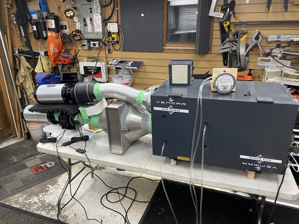
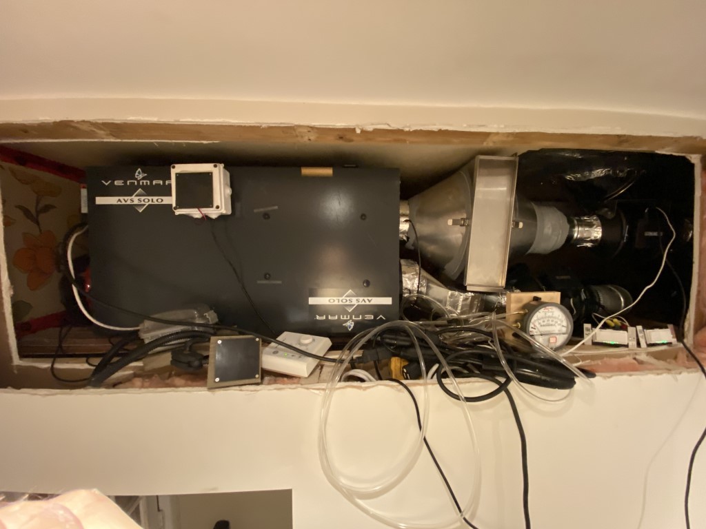
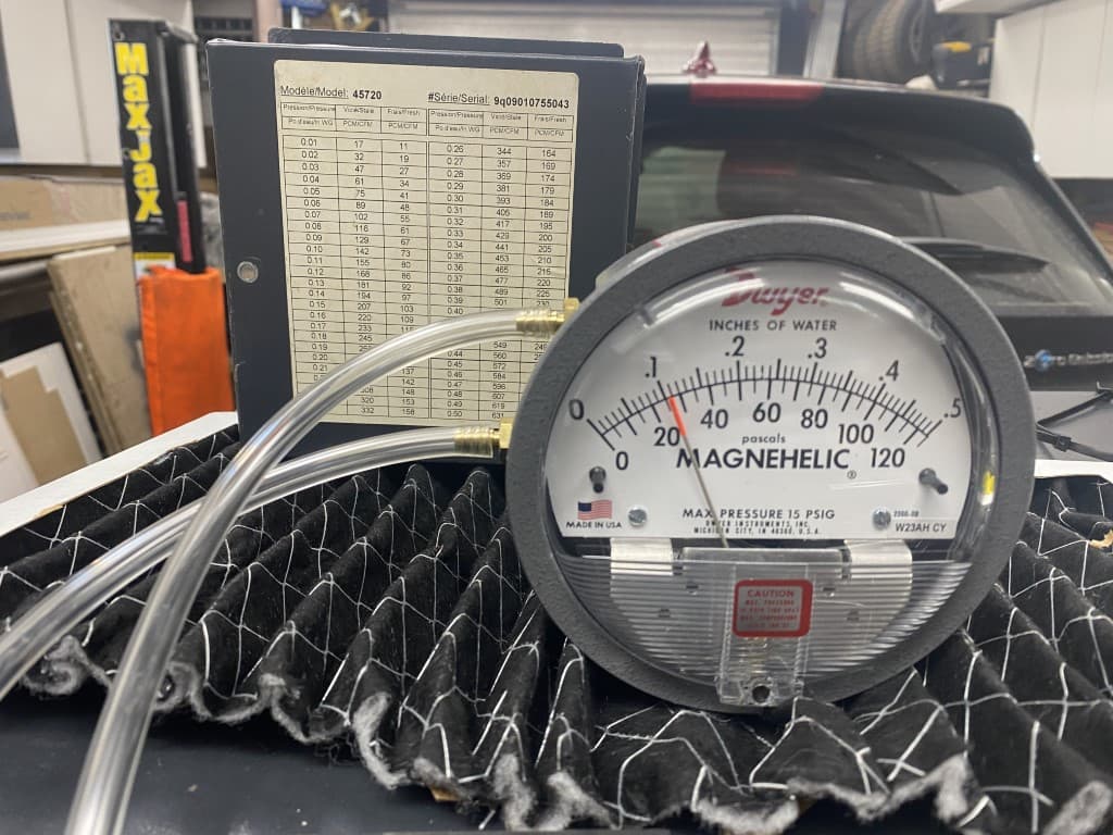
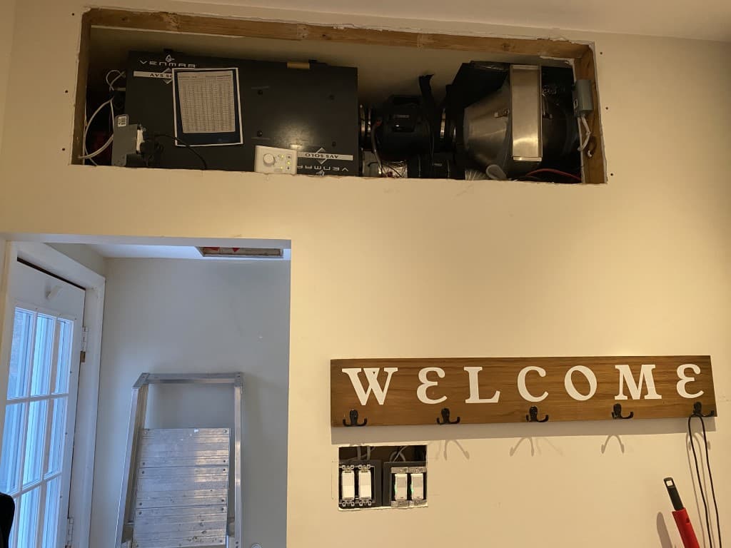
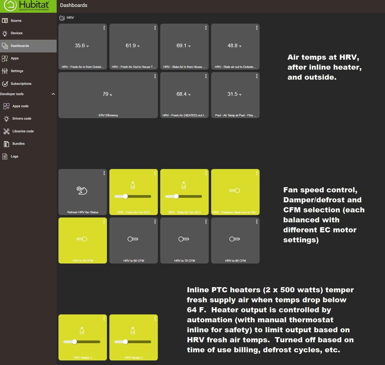
I'm working on an HRV ventilator that can be controlled dynamically to provide make up air with kitchen exhaust fan use (already automated), vary speed on occupancy and potentially avoid defrost cycles by ramping exhaust over intake when the core temperature drops. Staging here to figure out the package sizing, filtration (MERV 13 via 14x14x4 inline filter). I've also got a solution for filtering wild fire smoke using an internal carbon canister. The OEM motors and housing have been removed from this HRV, hence the external EC fans.

12 Likes

Here are the settings on the Leviton driver that correspond to about "half" speed on the AC Infinity controller. I'm finding the comparitive scale on the Leviton units much lower, as you can see by the driver numerical level setting (12=exhaust fan and 30=intake fan) that correspond to 60 CFM measured flow over the HRV core. In other words, the settings 12/100 and 30/100 on the Leviton Dimmer, correspond to settings 5/10 and 6/10 on the AC Infinity controller.

Any thoughts on perhaps a resistor on the Leviton 0-10V signal wires to increase the scale so say 50% is actually 50% motor speed? It's not an issue for automation (as you have 0-99 levels to choose from) but it is if you plan on adjusting speed manually via the 10 step dimmer on the physical switch.

I may have a sink vs source issue: https://assets.lutron.com/a/documents/048587_Web.pdf

1 Like

Awesome work.

1 Like

Thanks @velvetfoot :slight_smile:

I've got the system shoehorned into place, with a lot of clean up work to do. The good news is that CO2 levels in our home (100 year old house with extensive energy retrofitting) dropped from a morning high of 1700 PPM to less than 800 pretty much overnight.

I've mapped out the fresh air /exhaust air EC motors to the balancing chart on the HRV so can use these motor (dimmer) settings to dial in the motors to different CFM values.

The integration with the kitchen exhaust hood (also an EC inline fan) works awesome so HRV ventilaton rates are mapped to the kitchen exhaust hood fan. Using the induction cooktop triggers the kitchen exhaust fan, which in turn sets the HRV to accelerating CFM settings. It's awesome :slight_smile:

This is a mess, but it works. Some more tweaking to do..

This is the balancing chart that is now correlated to motor speeds.


There are still many hours of work to frame the opening, make a door, and install wiring, switches etc.

Having sensors on all four air streams makes for some interesting experiments. For example, if you ramp exhaust right up and drop the fresh air motor CFM down, you can get some crazy efficiency numbers. 95 % efficiency is pretty much impossible with an air exchanger, unless you unbalance as I did here. The warm "stale" air is flowing out through the core at a much faster rate than the fresh air cold air coming in, hence the 95% efficiency measurement!

2 Likes

Awesome. While this is mostly above my head, I believe I have a mixing valve that I installed on the exit pipe from my pellet boiler buffer tank (memory is fading over time, lol) that is 0-10 volt controlled. I installed a honeywell, I think, controller to control the valve based on a couple of temperature inputs. I just remember when I was looking into it, that 0-10 volt control is used a lot, so your work is useful. I still have trepidation about using Hubitat for mission critical stuff, but it doesn't seem that anything catastrophic would happen in your case.

I may have missed it, but what are you using for air temp sensing in your various streams? That could be critical if it's not timely.

Are you in a radon zone? That's a whole other thing, though related. I'm not sure if my Fantech fan has an ECM motor, but it's only 15 watts anyway. My boiler circ pumps are all ECM now, and I think they might be able to be controlled by 0-10 volts.

I once had an overhead fan with an ECM motor. I wonder if that could've been controlled by 0-10 v.

Anyway, I'm probably way off base.

Excellent work.

1 Like

@Velvetfoot , the 0-10 V thing is a big one I think as there were precisely zero solutions for zWave or Zigbee control aside from the Leviton product which (up to now anyway) was never documented :slight_smile:

I do have DS18B20 sensors in each of the four air streams as you can see below:

I have a virtual Temp sensor which calculates live ERV efficiency values based on those temps, bottom left in the pic. There are also a few more sensors (like the Pool - Air temp) which are used in summer to control my pool solar heating system. That one gives me outside ambient temps, which correspond pretty closely with the "ERV Exterior Intake Air Temp".

If the device has 0-10v control, you can likely use the Levition 0-10V dimmer to control it. Radon is a not a big issue for most here, but regardless, you don't want a house under negative pressure (pulling air in) particularly in very cold temps. Controlling your HRV this way (with two ECM motors) allows you to "add" some air into the house when for example the kitchen exhaust fan is fired up.

You're not off base at all..you get it :slight_smile: To me, having an option for 0-10V control that can integrate with Hubitat or Smarthings has a lot of possible uses here in NA for smarter homes. That's why I was pretty stoked to get this working.

In general, you want air coming inside the house via an HRV/ERV to match air leaving. The magnehelic differential gauge lets you measure that using the HRV door ports. You use the balancing chart that is posted on your HRV/ERV to convert the magnehelic readings to CFM. I just tweak the motor speeds (via Hubitat) until the magnehelic (inches of water) reading matches the chart for my target CFM readings. Hope that makes sense.

I'm no expert...just learning as I go along :slight_smile:

image

In Hubitat I've created several scenes like this one which set the intake/exhaust motors for balanced air flow. The intake has to work much harder than the exhaust due to the HRV core design, filtration, etc. Level 40 on intake with level 25 on exhaust (the current setting) works out to a balanced 55 CFM.

Fireplaces or wood burning appliances can be a challenge in a "tight" home, but controlling ventilation via ECM motor control means you can add some air for example when a temp sensor triggers an automation. In my case, I would ramp up the intake fan (so deliberately unbalance) the HRV to replace air leaving the home via the fireplace. This in turn can eliminate back drafting when you load wood etc. I have that exact scenario working now when the kitchen hood exhaust fan automation is triggered by the induction cook top (power use) detected.

Kitchen hoods, HRV/ERV, bath fans etc. only work when people use them...so automation can make a big difference in these situations to keep interior air quality where it should be.

1 Like

I replaced the HRV intake 4" fan with a 6" EC fan, also from AC Infinity (Edit: Not from Fantech). It's their cheaper EC fan, which as far as I'm concerned is 100% ok. The motor mount is plastic, and it does not have the connecting block as I've pictured in post #1 for the S4 (more expensive fan).

https://acinfinity.com/inline-duct-fans-lite/

The one gotcha, is that you'll need to cut off the USB-C type connector on this fan to expose the four wires. The included Molex connector does not have pin 4 connected internally, which you need. If you cut the USB C off, you'll see the four wire colours

AC Infinity Yellow to Leviton Violet
AC infintity White to Leviton Grey
AC infinity red and black not connected.

As far as I can tell, this fan is identical to the more expensive ones, but a cheaper case.

1 Like

I've officially applied for "extreme project rabbit hole" therapy :slight_smile:

I'm finally wrapping things up with this project having run the HRV drain hose (to a nearby laundry drain), done the rough wiring and installed inline electric heaters to condition cooler supply air. The Hubitat hub is running the show pretty much completely.

In normal operation, total power use is about 28 watts for the two EC fans (in the 50 CFM profile), and I'm adding in about 150 watts of post-heat when outside temps drop below 25 F. One of the perks of a system like this is that when the system calls for 60, 75 or 90 CFM, the EC motors are dialled up individually based on actual flow testing at the HRV.

Two zigbee dimmer modules limit power to the heaters, modulating their output based on supply and delivery temps. It's a pretty slick setup.

Still lots of work to do, but the EC fan control switches and inline heater switches are wired up (under the welcome sign). They allow manual control if required. The missus is not a fan of visible technology so a sweater or two on the hooks will hide the switches. They are managed by automation so if someone hits a switch, it won't be an issue. I want them there so I can give them a quick visual to make sure all it working as advertised. If the automation system is off for some reason, the switches can control the system as well.

The inline heaters can raise the fresh air supply temps 40 F, but the typical requirement will be about 10-15 F as outside temps fall below -10 F. I ended up doing this as the fresh air "dump" is into our main living area and even at 80% efficiency, with outside temps dipping well below freezing, the supply temps tend to cool down the space.

There are five levels of safety built in to the heating setup: 1. The PTC heater by design uses less power as it heats up. 2. If the unit itself exceeds 220 F or so, the integrated thermal switch turns it off. 3. I've added thermal fuses inline in the junction box for the housing 4. The remote bulb line level thermostat cuts power if the heater housing hits 70F 5. The automation system modulates power and turns on/off the heaters based on the HRV mode.

Finally, I've added manual switches to cut power if needed.

These PTC heaters are all of $17 each.

This remote bulb (part number A19ABC-12C) line level thermostat can manage the heaters just fine if required. Right now it's just there as a third level of safety. If the housing exceeds 70 F, power is cut to the system. It's 100% old school manual, so no power is required to operate it.

The automation bits are all working surprising well. The system defrosts itself depending on outside temps which amounts now to this routine:

  1. Close outside air dampers (which opens internal recirc damper)
  2. Switch to the 75 CFM profile for x minutes (based on outside temps) to warm up the unit/core.
  3. Stop for a minute (to allow any water to drain with neutral air pressures inside the HRV)
  4. Open the dampers and dial back the EC motors (mainly to 50 CFM).
  5. Turn on and modulate the inline heaters if required.

Everything is done in Rule Machine 5.1

Now I have to make it all pretty :slight_smile:

1 Like

Wow!

You better hope Hubitat doesn't go out of business, lol.

I've done similar with Smarthings (webcore), Vera etc.

But ya, I had to port over from ST to HE based on the whole groovy thing. I relax a bit more knowing HE is local for execution. If all else fails, the system can be adjusted via the dimmer/switches and run 100% without automation. The only bits left really of the original HRV is the damper system and temperature sensor. I've unplugged the temp sensor and installed a 10K resistor instead so it thinks it's warm outside. If I plug the thermister (sensor) back in, it will do the defrost thing based on jumper settings.

#rabbithole #needtherapy #haha.

A final plug for Terrabloom's customer service. I'm using a 6" EC fan from them in my kitchen exhaust which just started running full tilt 100% of the time when the system powers it up. The controller is ignored. One email and I have a track already for a new unit. Nicely done!

1 Like

Final piece of the puzzle with respect to the ventilation system is Co2 sensing so I can drive the HRV at the 55, 65, 75 or 90 CFM configurations (or off completely) depending on real time air quality in the home. To that end, I ordered up these two items, the Ecowitt G1100 gateway and Ecowitt WH45 air quality sensor. These are powered by USB (they don't include the wall wart, just the USB cable. They are not super expensive about $150 for the pair. Turns out our air quality in our home is quite good with PM 2.5 and PM 10 levels at 0.1...which is very low. Those two are measurements of particles in the air, where PM 2.5 are of particular concern as they can reach your blood stream via inhalation. These particles are small enough to travel all the way through your lungs to the alveoli where gas transfer is taking place.

The G1100 WIFI gateway connects to your home WIFI and then their sensor devices (many can be added including outdoor weather stations, soil moisture sensors, etc) connect to the same gateway via 915 Mhz radio. The gateway has a built in web server to display data so the system does not require an app, cloud account etc. to operate. More importantly, it can send data to the Hubitat automation hub. Specifically Co2 levels are sent every minute or so, which in term now drive the HRV system depending on levels of Co2 detected.

There is a very nice integration written for Hubitat which is 100% local code, no cloud accounts required. The integration is maintained currently by @sburke781 who has a done a great job with it. The G1100 gateway sends data to the Hubitat hub every 60 seconds. It was a bit of a process to get everything set up but has been rock solid since installation.

I was tipped off on an issue with my older Co2 sensor which had automatically calibrated itself to inside air and was reading nearly 350 PPM low. I had to factory reset it, and it now reads very close to the Ecowitt WH45.

This is what the live data feed looks like from the G1100 gateway's built in internal web server:

The gateway is very compact and like the WH45 is powered by USB. The WH45 can also run off two AA batteries installed in the base, but reports less frequently when run this way. You can view the live data via an app (free cloud account required) or via the internal web server on the gateway. I purchased these after reading all the great reviews by users here on the forum.

3 Likes

Great write up @denwood , and glad to see you getting a great result from the sensors and the HE integration.

1 Like

@denwood I came upon your use of the Leviton switch from google searching and I have a question, or a few questions rather regarding the same ZS057-D0Z you're using.

It's not exactly specific to the hubitat platform (so I'm not sure if a back and forth on here would be allowed), but I'm trying to troubleshoot why my switch isn't working as I think it should.

  1. When wired up, taking a multimeter and reading the voltage of the purple 0-10v lead should give a figure of 0-10v depending on the current setting on the switch itself, correct?

  2. You've stated using these on a fantech ec fan, which is what I am trying to do. For the fantech EC, the purple wire should go to the yellow 0-10v, and the grey should go to the blue low voltage ground, in their wiring diagrams, correct?

My switch currently functions for mains power properly, but the purple 0-10v lead will not give any voltage signal at all regardless of the switch level when reading it with a multimeter. I'm wondering if the switch itself is broken, I also purchased it from aartech recently. Connected perfectly fine on my zigbee network.

Thanks for any insight!

Thanks Simon ( @sburke781 ) There are many hours invested in that integration...and I'm guessing quite a few of us here using it :slight_smile:

@Kyl , I'm sure it's fine to discuss any platform if the discussion helps out with integration.

The multimeter should be across the purple and grey wires to check voltage, but it may not behave as you'd expect when not connected to the device you are controlling. Purple is positive, grey is the reference ground for the 0-10V signal.

I did not test a Fantech fan...just AC Infinity and Terrabloom. I fixed my typo in the post referencing. What fantech motor and controller are you using? I would test the motor with their controller and a multimeter to check and see which two wires are showing voltage changes with speed. They may have a 10V supply positive and ground (as the AC Infinity and Terrabloom do) to provide power to their controller and or reference voltage for a cheaper potentiometer. In that case, Red, Yellow and Blue will be connected to their pot. That 10V signal will not change with speed changes...it will stay at 10V. The EC fans I've tested so far run full speed if there is nothing connected to the 0-10V control wires.

In the google image search, I did see a Fantech FG 10 EC wiring diagram where yellow is 0-10V, and blue is the low voltage ground so I'd say your wiring is correct based on that.

Also, are you testing this with their speed control disconnected? You would 100% need to do that.

Another thing to check in your hub (which is what?) is that the min/max levels are not restricted on the dimmer, or local control (not sure if that is even an exposed property with this dimmer) is not disabled. You might want to exclude the dimmer from your hub, do a factory reset, and try it again via the controls on the dimmer before inclusion. You should see the LED indicator on the left side of the switch cycle through about 10 levels as you dim/brighten manually, or via your hub.

1 Like

Hmm, I must be missing how to intemperate how the switch itself operates then, I thought it would output a 0-10v signal from the purple lead on its own.

This is the fan: Fantech RVF 4XL EC Ext #44860
" Optional control via external devices outputting 0-10V signal such as temperature, occupancy sensor, gas detection, humidity, etc. "

The fan itself ships with a potentiometer 'wired' into the red 10v, yellow control and blue ground, it has no external controller. You can remove it and instead control the fan externally with a PLC system, something outputting a 0-10v, etc.

With the switch's purple/grey not connected to the fan there is no voltage coming from the purple. With it wired into the harness on the fan itself purple to yellow, grey to blue, still no voltage.

What I'm starting to get out of this is I need to have something in between the switch and this fan for things to work.. The fantech support said 'yes, it (the switch) should wire similar to the diagram (yellow / blue), they weren't much help quite honestly. There is no on-fan controller that I can see.

The hub is just HA, very basic integration and nothing disable-able. Physical controls on the switch cycle through the side levels but again, if checking with a multi-meter, nothing is being sent on that purple lead.

From what I can figure from that wiring, yes remove the pot wiring and attach the dimmer purple to fantech yellow, and dimmer grey, to fantech blue. Then you should see voltages change as you change dimmer settings on the Leviton dimmer, along with the fan speed changes.

Check with the pot attached on the fan (no dimmer wires connected), between the yellow and blue, but also check the yellow and white. What do the voltages do there as the fan speed changes? I'm also assuming that you have the dimmer neutral, hot and ground correctly wired.

Check to see that the grounds and neutral are bonded at the panel at both switch and motor locations too. You can check for continuity between them with power off. I'd guess that if both don't have a common ground, you would run into issues.

If you are seeing zero voltage on the dimmer 0-10V between purple and grey (connected to fan) then yes, there may be an issue with the dimmer itself.

Yep, zero voltage ( well, like 0.005), effectively zero, doesn't change) on the dimmer 0-10v purple and grey while connected.

With pots on, variable between the yellow and blue, nothing between the yellow and white.

Home wiring is proper at the panel.

I am going to reach out to AARTECH / Leviton tomorrow and see what they say. As I understand what you're saying, there should at least be some noticeable voltage coming out of the purple when it's wired to mains and to the control/ground on the fan.

Thanks for the help

Post back here with the outcome...for the next guy :slight_smile: Curious to see how this one plays out.

I should add, fan is running with their pots on, and while connected to the switch without the 0-10v connected. Variable with the pots works perfectly fine.

Will let you know how it goes

All done with drywall, paint and trim. The heaters are running nicely controlled by a set of Zen72 dimmer switches, (on the left) and the two on the right are the Leviton 0-10V dimmers controlling the fresh and stale EC fan motors. The original Venmar wall control is connected, but all it's doing is telling me (via the status LED) when the unit is on (via Fibaro Smart implant dry contacts) or off for defrost. I can also see what speed the system is running at via the Leviton dimmer LEDs (10 segments) on the side of each switch.

This is our back door mudroom, and that high ceiling gave me some room to tuck the ventilation bits in without intruded into the living space :slight_smile:

I'm using a Fibaro smart implant to record all the temps, but I also have the dry contacts on the implant attached to the HRV remote contacts. This way I can control the HRV dampers for defrost cycles..all running via HE.

1 Like