So. (obviously?) the node is connected to the relay. Relay only switches on when the node tells it to, and thus only allows the actuator to receive power when the node has powered the relay.
Project isn't entirely finished - I prefer to have my smart stuff operating as smart and also appear as dumb. So I still want to build a control box for the hallways so we can see at a glance what's going on, have switches to fire up the boosts, enable the schedules etc.
Now I've discovered WLEDS, it'll be cool to have one led which will be different colours depending on whether something is on, off, boosted, too hot, too cold etc.
I use 2 cables. Both 2 core. The actuator only has a live and neutral and I run this off a 2amp fused plug. The 2nd cable is +/- from a dc psu.
I also already had some 6 core (I think) alarm cable which I used to run from the node to my temp sensors which need 3 (+/-/data). The intention is to (on some) add in a door contact sensor and motion, all on the same node.
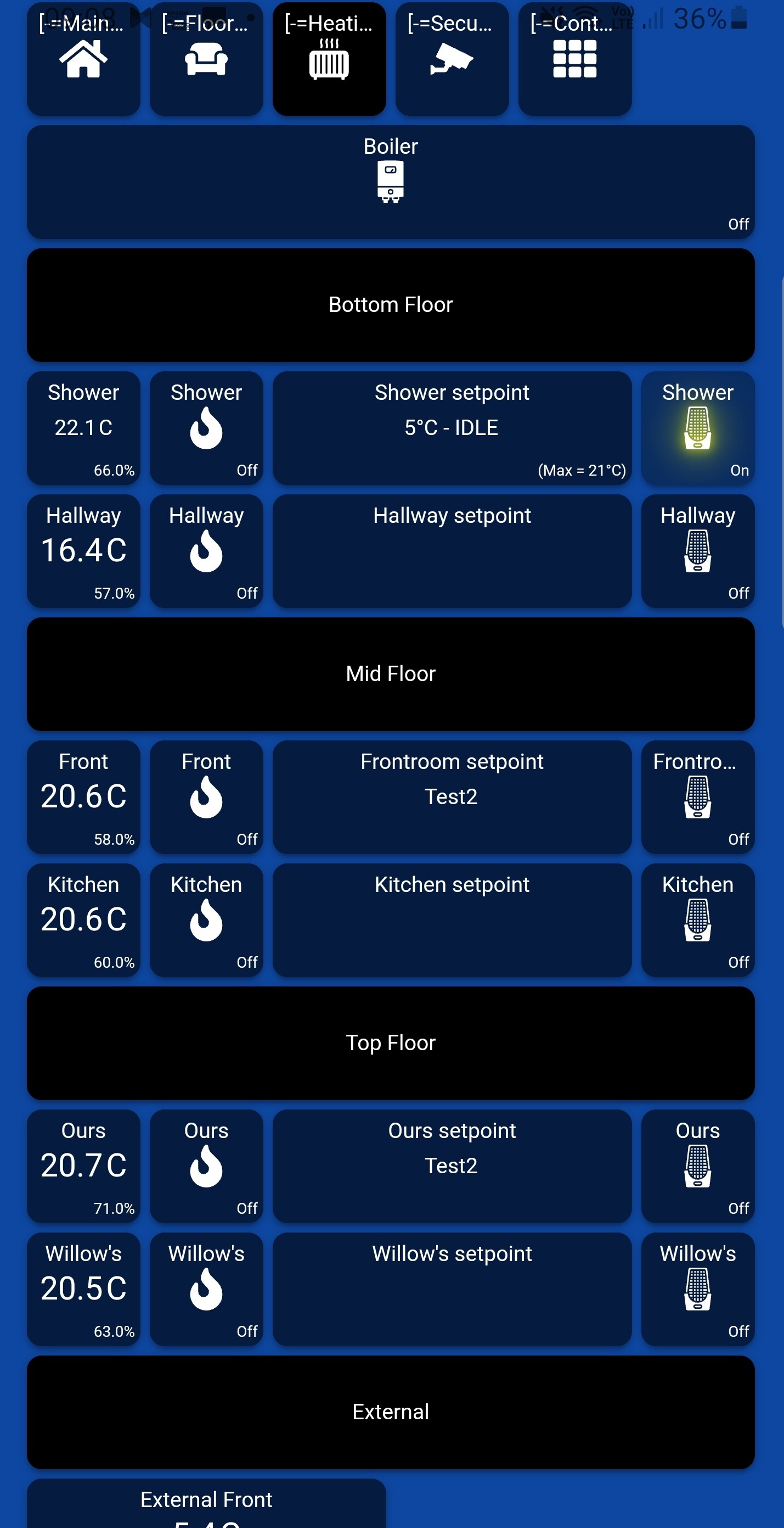
The particularly cool bit (for me) is the webcore and the dash.