You will need to use "tuya-convert" or something similar to get the initial firmware on.
I use an old Raspberry Pi 2 with a super cheap Wifi USB dongle to do this. There are many other approaches though, depending on your technical know-how and what you run for computers in your house.
Unfortunately not with that device, when it comes to Sonoff stock to Tasmota OTA is only possible with BASICR3,RFR3, MINI and D1 since these are the only models which support DIY mode.
When flashing over serial (which is very easy on your model once you get the USB-TTL dongle) you can go straight for my Tasmota-version, no need to use any others. That is a need when running Tuya Convert, which is not supported on Sonoff devices.
I remember there being a way to at least sometimes recover from this without going the serial flashing route. I'll have a look. The Minimal build is very dangerous to use when not already running Tasmota on the device, it almost always ends up in this way.
Not for Sonoff devices unfortunately.
EDIT: @uptownruss There is a possible OTA solution I have never tried:
Hi @markus and thanks for your reply and suggestions. Yes, I actually tried Sonata before posting here. The issue is that it seems to no longer work with any newer firmwares and I fell into this category. I suspect anyone buying a unit now has a firmware newer than will work with it. Please see GitHub - mirko/SonOTA: Flashing Itead Sonoff devices with custom firmware via original OTA mechanism where it says: " ATTENTION: It appears SonOTA does not work with devices running current firmware"
...so it sounds like OTA is not an option for me and I am required to flash via a physical cable and dongle then... Bummer, but oh well. I was hoping to do this tonight but I'll have to get one.
I had to confirm this and as I suspected, when you get that AP mode, you're in the Arduino bootloader. It MIGHT be possible to use the Arduino OTA feature to port 50000 in order to get Tasmota flashed properly, but I have never done that and am not even sure where to begin searching for that.
The only other possible route (except USB-TTL) is finding the reset procedures for your device and try it that way. It could get you back into a working mode, it could also make it so that you don't even get to enter the Arduino bootloader again.
Looking at the reviews that one looks unreliable. It is also not clear if it can be set to run the serial connection with 3.3V instead of 5V. It has both as outputs, that doesn't mean it can be set to communicate using 3.3V.
Do remember you need something to easily keep the connection with the board. I don't know how the connectors look on your particular device, but for many device you either have to solder or come up with a way to hold the pins in place. Easiest to just hold pins is place is with something flexible (like pogo pins or something else similar).
In general all devices you will flash are 3.3V since they are based on the ESP8266 chip. It is however much easier to flash all devices if you can find one that can supply up to 500mA of power as well (very few do this). It makes for a simpler connect since you don't want to be running on mains power and connect the TTL at the same time. That can go badly. You can do it with the 500mA supply, but you may end up with weird transmission issues at times.
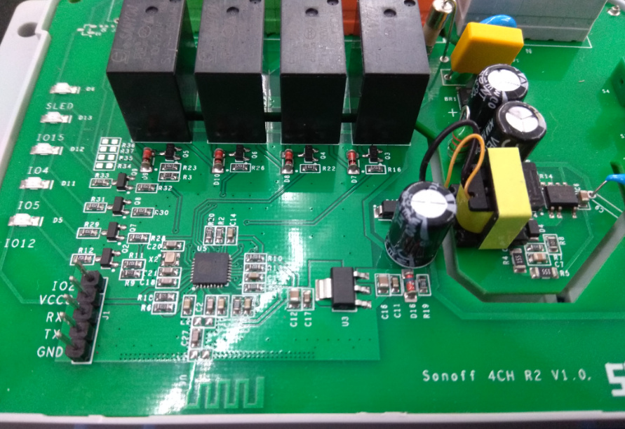
Ah, excellent point and I wasn't thinking about that. It still seems the third dongle should work fine for this device at least. I haven't opened my unit, but this is a picture of the PCB I found while searching and it already has pins there:
Ahh...another interesting point. I have a usb power meter somewhere. I should test my USB2 and USB3 ports on my pc. Also, I can test my portable fast USB charger as well. ....unless you're saying the dongle itself may step down the power regardless of what's coming into it.
You're just full of good points for me to watch out for! Haha..thanks
This device looks very easy as long as you have the female dupont connectors to connect with Most devices are NOT this easy.
The normal USB spec is 500mA, so that is not the issue, the question is what the usb dongle delivers over 3.3V. What you get from the USB port is 5V. Before I found a USB-TTL dongle that could deliver 500mA I had to get my 3.3V power supply from another USB to 3.3V adapter connected to the same USB port (to ensure the ground was the same). This quickly became annoying. I've noticed most dongles don't even specify this. I can unfortunately not point you to the one I bought. I live in China. I think that if you buy the third one you linked to you will be fine with at least this device. Just don't connect it to mains while flashing
I extended my portscan and 50000 was not open. I also connected the WiFi to my PC so that I could run more tests and the Arduino IDE is not finding the board at all.
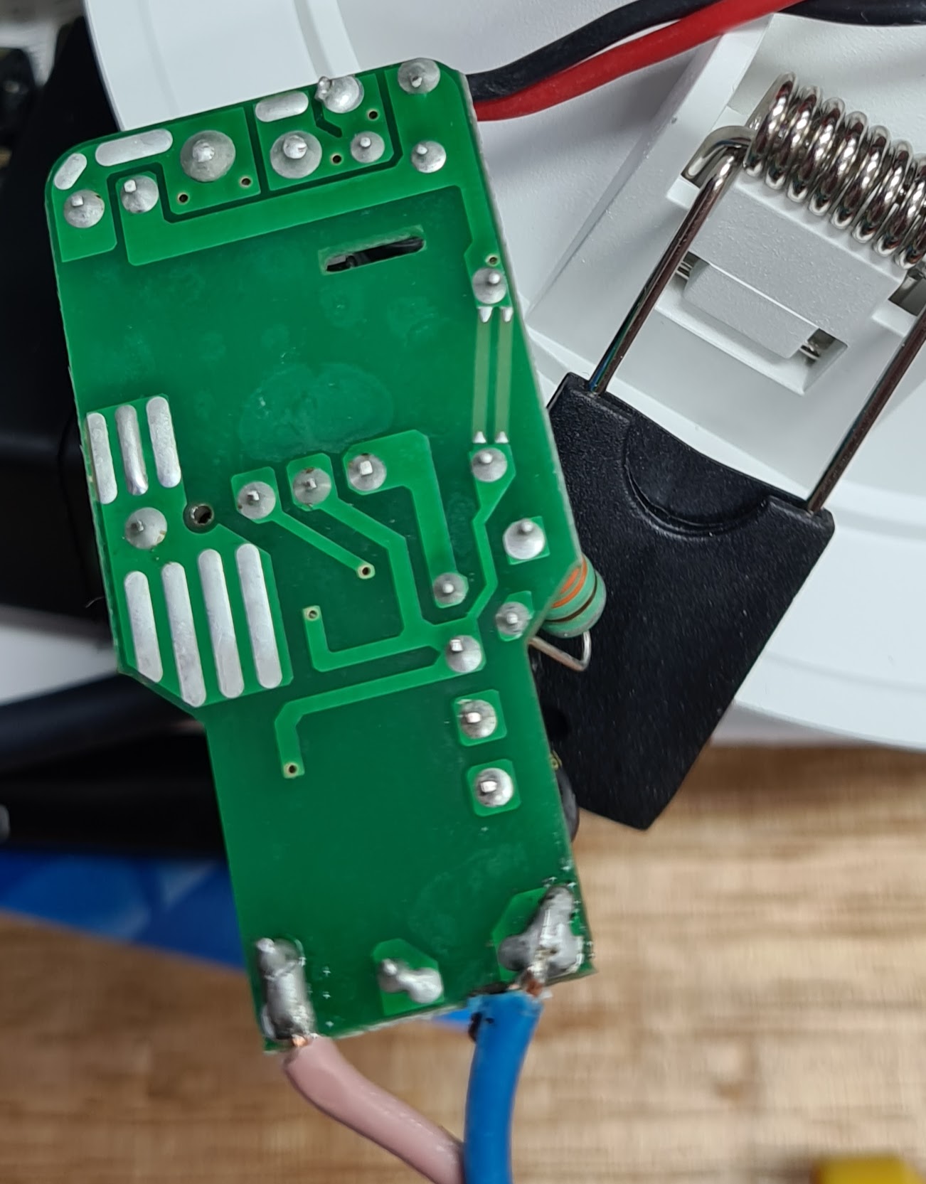
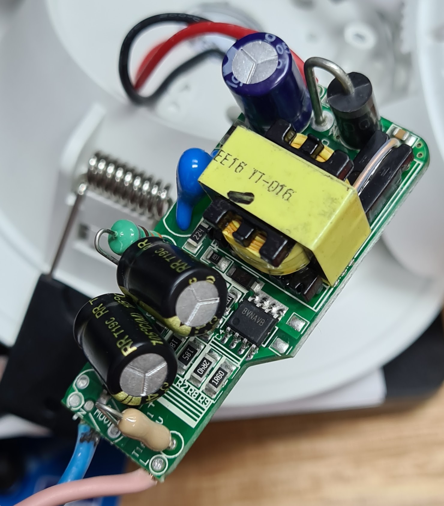
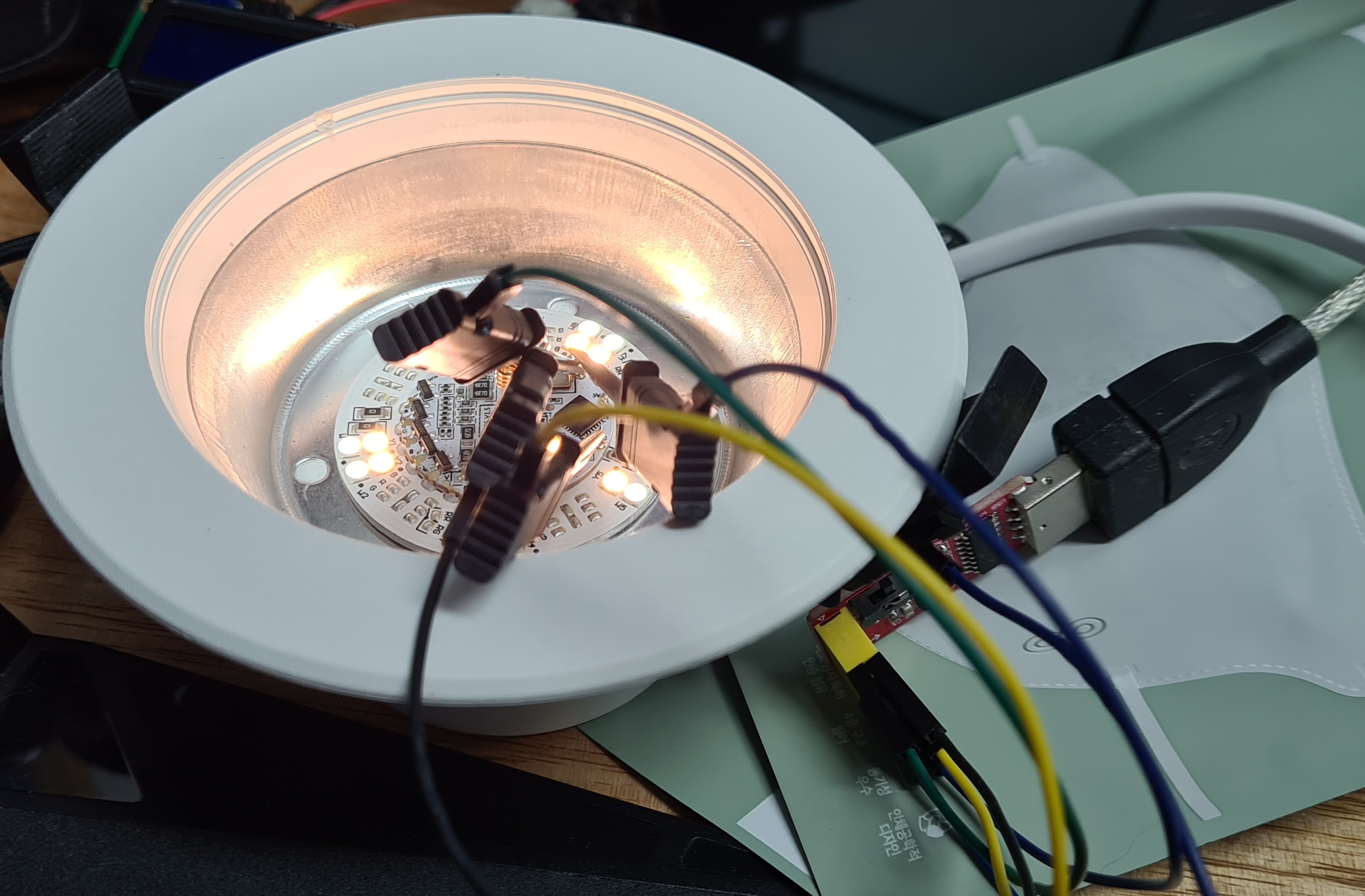
I think that it is time for the serial approach, however, take a look at this main board... I don't even see anything that resembles a CPU!
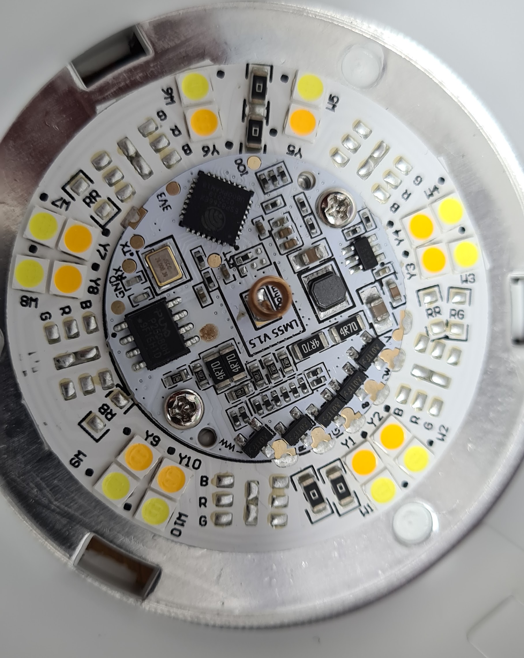
All of the other devices that I have messed around with have had ESP modules on them, or ESP chips. Unless the module is built into the actual LED, I can't see how this works.
I was afraid of that, it certainly just looked like a PSU to me. I have now confirmed that when I stick 16v on the red and black leads (which was the voltage that I was reading when 240v was on the mains side), the wifi starts up. This means that the brainbox is inside the body of the light. Definitely going to do a teardown video/post for this one! Next step, figure out how to open the case. I think that I will try to remove the plastic difuser from the front.
Yes, and super easy to solder some resistor leg offcuts to the pads so that I could use the pin jaw probes from my logic analyser. I am really enjoying playing around with hardware again. Most of the Tuya type devices that I have converted have had some challenge or other.
The Tasmota for HE firmware is very nice though, has been super reliable, once I figured out the "auto-bricking" that happens when you flag the wrong button and it thinks that it is being reset
@Abhijeet_Ghosh for the updates to work with my Tasmota drivers you need to run my modified version of Tasmota, as stated in the installation instructions.
@markus it just says add emulation of hue Bridge if you want auto discovery. I don’t want this. Where is the bin file for the custom firmware? If it will work, then I will happily switch my dimmer to your app
@markus what does reset 5 do? I don’t want to break anything. I have some led settings and power on settings, as well as I disabled MQTT. Will this all go away?
This will all go away. You will need to set up the device from scratch, which would just be a few commands anyway. MQTT is off by default in my version. My HE drivers control some other sensible defaults.
@markus last question, thanks for being so helpful
In my router, I have set the MAC address of the plug to be a certain ip. I have many webcore scripts that send http requests to the smart plug. Will this still work (the regular integration). Also, will the smartthings integration continue to work with your firmware? I am sure the iP will not change