I am a complete noob when it comes to this and all I want to do is setup 2 ultasonic distance sensors to check if the cars are in the garage or not. This is what I have:
2 x Wemos D1 mini
2 x HY-SRF05 (Ultasonic sensors)
I have loaded all the Hubitat child drivers and now I am completely lost, I know I have to upload a sketch using Arduino IDE. I found this one but I don't think it is for the Wemos D1 Mini and I dont know how to change it. I did edit the wifi ssid and password and the ip address and commented out the SmartThings hub port and used the Hubitat port.
Any help would be greatly appreciated, just remember this is the first time I am even looking at these devices.
P.S. do you just copy the txt from the sketch and paste it into the Arduino IDE page?? Sorry so green.
EDIT: Okay have no idea how, but I know have this in Hubitat as a virtual ultrasonic device. What I wanted to ask is how often the sensors updates the distance and how can I use this to check if a car is in the garage or not. Currently it is giving me the number of liters in a tank?
Sounds like you’ve made some good progress. The Utrasonic Child Device was originally written by a user who wanted to monitor the level of water in a tank.
Since you want to monitor whether or not a car is ‘present’ in your garage, we need to make a slight change to your Arduino sketch. Please change the code
This will create a Child Presence device on your Hubitat hub. You can remove the Child Ultrasonic device as it really is not applicable to your needs.
Then, after the Child Presence Device is created, you should see a numeric “level” attribute. Also, you should be able to configure a threshold value to determine what ‘level’ will trigger the change from ‘present’ to ‘not present’.
Give those tweaks a go and let us know how that works out.
Thanks ogiewon, will give it a go, thanks for the help.
P.S Is it possible to speed up the ultrasonic reading rate, I would like to play around with how often it takes a reading. I have made the change and it is looking good.
P.S. Is it in the same line you asked me to change, maybe the 60 would be seconds?
Correct. You can change the polling interval by adjusting the 60 seconds to a lower value, but I wouldn’t go faster than 30 seconds. It will transmit data to the hub whether the value has changed or not. No need to send high frequency data.
Hi, I wonder if you could possibly help. I have setup the ultrasonic sensor and a D1 mini. This is to check if a car is present. I have set it up in the garage roof pointing down. it looked like it was going to work well. I left in my car and the reading still measures the same distance as if my car was still there? It did show one large measurement of 212cm (roof to floor, no car) after the car had left, then about 2 min later it went back to 108cm and has been reading this for the last 3 hours but my car is not in the garage. I tested this on my desk and it worked well, but this was small distances between 40cm and 10cm, nothing over that. Where could I possibly look?
I had an ultrasonic sensor go bad on me. Readings all over the range, depending on which pin/wire I touched. I replaced it and everything worked as expected. I vaguely remember warnings that 200cm was the practical limit but that might not be true.
Also, most of the Ultrasonic sensors I have seen require 5 volts to reliably operate. There are a few models that specifically state they will work at 3.3 volts. You may want to try to find a 3.3 volt version.
At my home I have a primary Asus router and two UniFi APs to expand coverage all using same SSID. This afternoon I noticed a firmware update was available for my UniFi APs and started the upgrade. My two ESP boards connect to one of these APs in my master suite given strongest signal. For whatever reason the ESPs lost connection and marked themselves as not present. I let them stay that way for several hours hoping they would eventually reconnect but no dice. Other devices like my Rachio, thermostat, iPads all reconnected. I ended up having to pull the power on both ESPs to reestablish a connection.
This is the first time this has happened. I have restarted the APs and applied firmware many times before with having one ESP since last summer. I only recently added the second. Curious if anyone else has encountered this situation and has a solution other than yet another smart plug for these boards.
@ogiewon , thanks on the D1 mini it has a 5v connection which I am using I measured it with a meter and it shows 4.7v. I am going to try another ultrasonic sensor and see if it does the same.
Be careful using 5v to power any sensors connected to an ESP8266’s GPIO pins. These pins are designed for 0v to 3.3v. Sending 5v to these pins may cause damage to the ESP8266.
What voltage does should the D1 mini have as an input voltage? I have it connected at 5v, but read online it should be between 6 and 20, but 12v was suggested. Then what voltage should the ultrasonic sensor be connected to 5v or the 3.3v. Sorry very new to all this.
According to a site the HY-SRF05 can use 4.5 to 5.5v
4.5V to 5.5V, as quoted below. Maybe my supply voltage to the D1 Mini might be too low.
"This has 5 pins and can be used in 1-pin trigger/echo or 2-pin. Measurement Angle: up to 15 deg • Measurement Rate: 40 Hz • Supply Voltage : 4.5V to 5.5V • Supply Current: 10 to 40mA • Connector: standard 5-pin male connector which can plug directly into breadboards."
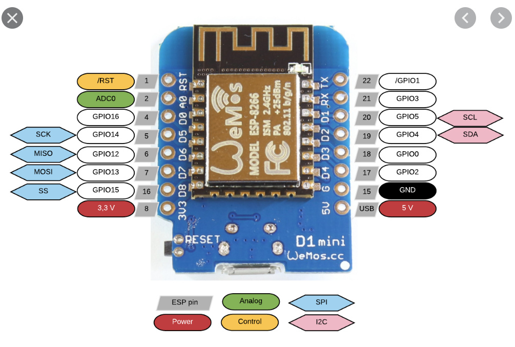
How are you powering the Wemos D1 Mini? If via its microUSB connector, then that 5vdc power from the USB power supply is what is probably exposed directly on the D1 Mini's 5v pin, as shown below.
I do not see any other pin that would allow you to supply a higher voltage to the D1 Mini. Some other micro-controllers have both a 5vdc regulator as well as a 3.3v regulator onboard. Those boards can be powered by higher voltage power supplies. A good example of this is the Arduino UNO R3 board, whose round barrel-connector can handle something like 7-12vdc. The onbaord 5vdc regulator steps this down to 5vdc to be used by the onboard electronics safely.
Most all ESP8266 boards have a 3.3vdc regulator chip onboard, which is used to step down 5vdc (from USB connection) to 3.3vdc to be used by the ESP8266 chip, and simple sensors that are attached to it.
ESP input pins should be at the 3.3 not 5v. Many wiring diagrams on the internet do not account for this but a few do show a couple of resisters to drop the sensors output down to what the ESP wants. Can you overdrive it and not kill the ESP? I have for a few minutes but I knew it was wrong and took a chance. Then I fixed it.
Yes I am using the USB connection which is 5v, the sensor also runs on 4.5 to 5.5v so that looks okay. What I have found is as soon as the distance goes over 200cm (actually about 208cm) it gives incorrect readings, it drops down to the 120's cms and jumps around there. I have read the specs and it says it should be good to around 450cm, but I am not finding this.
Anybody have this working reliably when readings are over 200cm?
I am trying to install this and configure for an Arduino Uno WiFi Rev 2. This is my first foray in to arduino programming.
When using the SmartThingsWifi101 sketch, I get a following error:
`
**/Documents/Arduino/libraries/WiFi101/src/WiFiMDNSResponder.cpp:26:10: fatal error: strings.h: No such file or directory
`
My understanding from previous research is that this is due to wifi chip incompatibility, and that it needs WiFiNINA library. I have tried including both regular WiFiNINA and and SmartThingsWiFiNINA libraries, to no avail. When I have tried to include the SmartThingsWiFiNINA library, it did not highlight in orange/gold, instead it just stayed black.
I have been able to upload the Arduino WiFi configs, and have it successfully connect to my network.
Any help is much appreciated! Apologies for the n00b questions, but I'm totally green with my arduino skills
Please try starting with one of the sketches that is designed to use the WiFiNINA library, like the " ST_Anything_Multiples_NANO33IoT.ino" sketch.
However, in the back of my mind...I can't help but recall that there may be an issue with that particular Arduino board and HubDuino/ST_Anything... I'll need to look through some old posts to see if it was a problem or not...
Thanks! I'll give it a try . If anything, what type of arduino board would you recommend that would also support WiFi and moisture sensors along with a dual channel relay?
What board did you select in the Arduino IDE Board Manager before attempting to compile the sketch I mentioned above? Try it with the Arduino Nano 33 IOT board selected just to see if it will compile. This will help you determine if you’ve configured your Arduino libraries folder.
 I'll need to look through some old posts to see if it was a problem or not...
 . If anything, what type of arduino board would you recommend that would also support WiFi and moisture sensors along with a dual channel relay?