I got you curious....I love it when that happens. 
@Ryan780 - do you have Private Messaging disabled on your account? I wanted to share some test code to see if you could run a quick test...
Try now.
See bold part for the main point (skip to that section if you find yourself falling asleep)
OK so I am a little lost... but have it working. My questions will slow down as I get familiar with this as I am sure this has all been covered in this long thread. It's only day 2 for me but things are starting to come together.
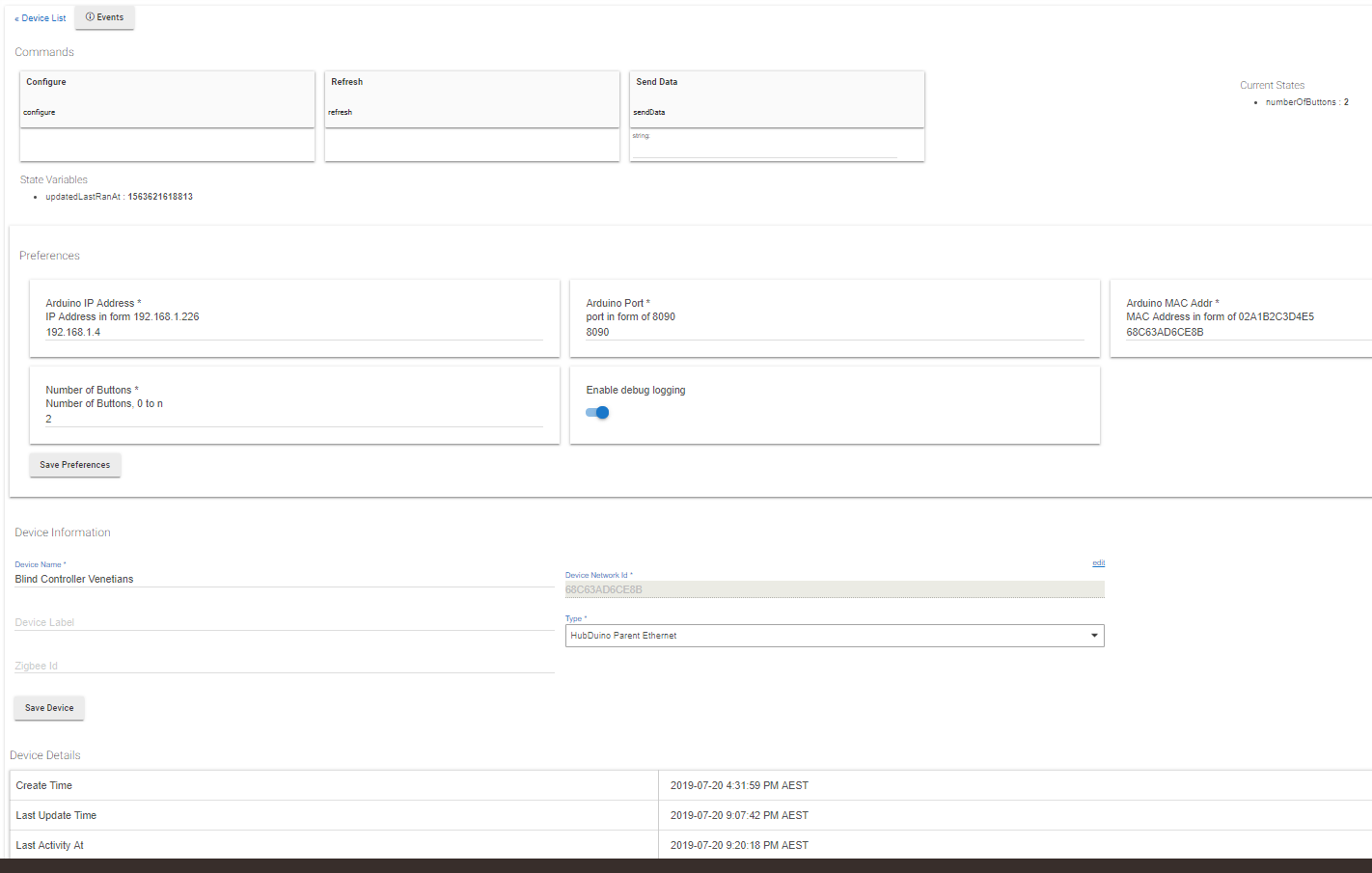
I have the servo code all working on my wemos mini (esp8266 wifi) but not fully convinced I am executing it the best way... So I only have the Hubduino Parent Ethernet shown as a device. I understand this is the parent device, but I don't see any reference to a child device.
If I Send the code from inside the senddata box inside the hubduino parent ethernet device however "servo1 50:1000" it sends the servo to 90 degrees in about 1 second so its owrking.
I then went and sent a custom code (as a button) in one of my rules as an action and it worked. Is this how you do it?
I was sort of hoping to send a number so I could add to it or use a slider. This way it is only a string so I am not sure how I can do mathematics on the angle to rotate 15 degrees every 1 hour. Maybe I just send a new full string every hour or maybe there is a way to convert a string to a integer?
All My roller blinds go down when the slider is at the bottom plus the Venetians closed, then only the blockout is opened when the slider is part of the way up plus the Venetians change to 80% closed, then the privacy/filter blinds go up and the blinds open to 50% once I slide to the top of the slider.
So other than the time of day and angle calcs (thus the need to change the angle every hour or so) it is working well.
Did you add all the Child Device Drivers from Github? You have to import all of the Child Drivers you are going to use so that the parent device can create the Children. They will show up underneath the parent device.
The drivers? Yes I did. At first I only imported the Child servo driver and the Hubduino Parent ethernet. Then I did all 27 of them when I didn't see the child device(s). I recreated the hubduino parent ethernet device again after installing all 27 drivers.
I have only tried the servo one as that is all I am interested in at the moment. I only changed the digital ports for the servo, the IP addresses and the wifi login details
can you show your edit device page for the parent and also your arduino sketch? If you're importing your sketch via text, use the preformat as code icon to help format it correctly.
1 Like
The commands are going through with senddata = "servo1 50:1000" but no signs of the child devices or any way to change the blinds other than sending that string.
//******************************************************************************************
//  File: ST_Anything_Servos_ESP8266WiFi.ino
//  Authors: Dan G Ogorchock & Daniel J Ogorchock (Father and Son)
//
//  Summary:  This Arduino Sketch, along with the ST_Anything library and the revised SmartThings
//            library, demonstrates the ability of one NodeMCU ESP8266 to
//            implement a multi input/output custom device for integration into SmartThings.
//            The ST_Anything library takes care of all of the work to schedule device updates
//            as well as all communications with the NodeMCU ESP8266's WiFi.
//
//            ST_Anything_Servos implements the following ST Capabilities as a demo of what is possible with a single NodeMCU ESP8266
//              - 2 x Servo Motor devices (using PWM output) - these utilize the "Switch Level" Capability
//
//  Change History:
//
//    Date        Who            What
//    ----        ---            ----
//    2018-06-24  Dan Ogorchock  Original Creation
//
//******************************************************************************************
//******************************************************************************************
// SmartThings Library for ESP8266WiFi
//******************************************************************************************
#include <SmartThingsESP8266WiFi.h>

//******************************************************************************************
// ST_Anything Library
//******************************************************************************************
#include <Constants.h>       //Constants.h is designed to be modified by the end user to adjust behavior of the ST_Anything library
#include <Device.h>          //Generic Device Class, inherited by Sensor and Executor classes
#include <Sensor.h>          //Generic Sensor Class, typically provides data to ST Cloud (e.g. Temperature, Motion, etc...)
#include <Executor.h>        //Generic Executor Class, typically receives data from ST Cloud (e.g. Switch)
#include <InterruptSensor.h> //Generic Interrupt "Sensor" Class, waits for change of state on digital input
#include <PollingSensor.h>   //Generic Polling "Sensor" Class, polls Arduino pins periodically
#include <Everything.h>      //Master Brain of ST_Anything library that ties everything together and performs ST Shield communications

#include <EX_Servo.h>        //Implements Executor (EX)as an Switch Level capability via a PWM output to a servo motor

//*************************************************************************************************
//NodeMCU v1.0 ESP8266-12e Pin Definitions (makes it much easier as these match the board markings)
//*************************************************************************************************
//#define LED_BUILTIN 16
//#define BUILTIN_LED 16
//
//#define D0 16  //no internal pullup resistor
//#define D1  5
//#define D2  4
//#define D3  0  //must not be pulled low during power on/reset, toggles value during boot
#define D4  2  //must not be pulled low during power on/reset, toggles value during boot
#define D5 14
//#define D6 12
//#define D7 13
//#define D8 15  //must not be pulled high during power on/reset

//******************************************************************************************
//Define which Arduino Pins will be used for each device
//******************************************************************************************
#define PIN_SERVO_1    D4  //SmartThings Capabilty "Switch Level"
#define PIN_SERVO_2    D5  //SmartThings Capabilty "Switch Level"

//******************************************************************************************
//ESP8266 WiFi Information
//******************************************************************************************
String str_ssid     = "######";                           //  <---You must edit this line!
String str_password = "######";                   //  <---You must edit this line!
IPAddress ip(192, 168, 1, 4);       //Device IP Address       //  <---You must edit this line!
IPAddress gateway(192, 168, 1, 1);    //Router gateway          //  <---You must edit this line!
IPAddress subnet(255, 255, 255, 0);   //LAN subnet mask         //  <---You must edit this line!
IPAddress dnsserver(192, 168, 1, 1);  //DNS server              //  <---You must edit this line!
const unsigned int serverPort = 8090; // port to run the http server on

// Smartthings / Hubitat Hub TCP/IP Address
IPAddress hubIp(192, 168, 1, 25);    // smartthings/hubitat hub ip //  <---You must edit this line!

// SmartThings / Hubitat Hub TCP/IP Address: UNCOMMENT line that corresponds to your hub, COMMENT the other
const unsigned int hubPort = 39500;   // smartthings hub port
//const unsigned int hubPort = 39501;   // hubitat hub port

//******************************************************************************************
//st::Everything::callOnMsgSend() optional callback routine.  This is a sniffer to monitor
//    data being sent to ST.  This allows a user to act on data changes locally within the
//    Arduino sktech.
//******************************************************************************************
void callback(const String &msg)
{
//  Serial.print(F("ST_Anything Callback: Sniffed data = "));
//  Serial.println(msg);

  //TODO:  Add local logic here to take action when a device's value/state is changed

  //Masquerade as the ThingShield to send data to the Arduino, as if from the ST Cloud (uncomment and edit following line)
  //st::receiveSmartString("Put your command here!");  //use same strings that the Device Handler would send
}

//******************************************************************************************
//Arduino Setup() routine
//******************************************************************************************
void setup()
{
  //******************************************************************************************
  //Declare each Device that is attached to the Arduino
  //  Notes: - For each device, there is typically a corresponding "tile" defined in your
  //           SmartThings Device Handler Groovy code, except when using new COMPOSITE Device Handler
  //         - For details on each device's constructor arguments below, please refer to the
  //           corresponding header (.h) and program (.cpp) files.
  //         - The name assigned to each device (1st argument below) must match the Groovy
  //           Device Handler names.  See the ReadMe for specifics!
  //         - The new Composite Device Handler is comprised of a Parent DH and various Child
  //           DH's.  The names used below MUST not be changed for the Automatic Creation of
  //           child devices to work properly.  Simply increment the number by +1 for each duplicate
  //           device (e.g. servo1, servo2, servo3, etc...)  You can rename the Child Devices
  //           to match your specific use case in the ST Phone Application.
  //******************************************************************************************
  //Polling Sensors

  //Interrupt Sensors

  //Special sensors/executors (uses portions of both polling and executor classes)

  //Executors
  static st::EX_Servo executor1(F("servo1"), PIN_SERVO_1, 90);  //last argument is the starting angle for the servo (0-180)
  static st::EX_Servo executor2(F("servo2"), PIN_SERVO_2, 90);  //last argument is the starting angle for the servo (0-180)

  //*****************************************************************************
  //  Configure debug print output from each main class
  //  -Note: Set these to "false" if using Hardware Serial on pins 0 & 1
  //         to prevent communication conflicts with the ST Shield communications
  //*****************************************************************************
  st::Everything::debug=true;
  st::Executor::debug=true;
  st::Device::debug=true;
  st::PollingSensor::debug=true;
  st::InterruptSensor::debug=true;

  //*****************************************************************************
  //Initialize the "Everything" Class
  //*****************************************************************************

  //Initialize the optional local callback routine (safe to comment out if not desired)
  st::Everything::callOnMsgSend = callback;

  //Create the SmartThings ESP8266WiFi Communications Object
    //STATIC IP Assignment - Recommended
    st::Everything::SmartThing = new st::SmartThingsESP8266WiFi(str_ssid, str_password, ip, gateway, subnet, dnsserver, serverPort, hubIp, hubPort, st::receiveSmartString);

    //DHCP IP Assigment - Must set your router's DHCP server to provice a static IP address for this device's MAC address
    //st::Everything::SmartThing = new st::SmartThingsESP8266WiFi(str_ssid, str_password, serverPort, hubIp, hubPort, st::receiveSmartString);

  //Run the Everything class' init() routine which establishes WiFi communications with SmartThings Hub
  st::Everything::init();

  //*****************************************************************************
  //Add each sensor to the "Everything" Class
  //*****************************************************************************

  //*****************************************************************************
  //Add each executor to the "Everything" Class
  //*****************************************************************************
  st::Everything::addExecutor(&executor1);
  st::Everything::addExecutor(&executor2);

  //*****************************************************************************
  //Initialize each of the devices which were added to the Everything Class
  //*****************************************************************************
  st::Everything::initDevices();

}

//******************************************************************************************
//Arduino Loop() routine
//******************************************************************************************
void loop()
{
  //*****************************************************************************
  //Execute the Everything run method which takes care of "Everything"
  //*****************************************************************************
  st::Everything::run();
}![Device_hubduino|690x439]
(upload://5LYruNM9lJg0nZzPwx8W41sSSyz.png)
You are using the wrong port. Hubitat uses 39501....you have your sketch set for the ST port number. Fix that and you will get your child devices.
const unsigned int hubPort = 39500; // smartthings hub port
//const unsigned int hubPort = 39501; // hubitat hub port
is what you have. comment out the ST port and uncomment the Hubitat port.
1 Like
Fantastic. That fixed it. As I could send the string commands to the parent device I thougth I must have had the networking part right.... Seems I didn't
That port is what gets the comms from your board to HE. And that is how HE knows how to build the child devices.
1 Like
I have started setting my Rf switches up in hubitat. Wonders of the broadlink rm pro being able to link to hubitat. Problem is the state is only recorded if commanded through hubitat (or Google home) so manually turning on or if my tasker box turns them on (still much automation left in tasker for now) causes problems with states so they don't operate properly sometimes.
So why post here.. Well crazy idea... Most of my lights are downlights and have sockets they plug into... I am thinking of powering an esp8266 of a socket. Likely using the button code and add a digital output to simulate the button push. Then have a hubitat rule check every minute to see if the button press is high (momentary switch held down by digital out permanently on) then the switch is on, if it's low (esp8266 switched off) then the switch is off.
Or maybe a do it by a rule that is triggered with a simulated short button press. Then use a digital output to simulate the button press and if hubitat hasn't seen a button press in the last minute then the switch is off.
What you think? Or is there a better way? I understand that there will be small delays in hubitat getting informed that the switch state changed when manually operated, but I don't think this will matter.
I don't really want to replace all (I started with 2x fibaro dimmers because they needed changing anyway) my other lights switches as I have quite a few to do, my current switches are nice touch Rf switches, I don't have a neutral in most of them so it's a lot of effort to change (without buying multiple dimmers for multi gang switches) , and the cost of the esp8266 checking is considerably less money.
I think the better way is to simply buy some IKEA Tradfri Zigbee Smart Outlets/Sockets and just plug in your light fixtures to those. This would provide robust, reliable bi-directional communications. ![]()
If I understand you correctly, you want a device that will allow you to detect whether or not an outlet is currently powered on. Then use this data to update the status of a device within Hubitat, correct?
I would simply use an ESP01 which, when powered on, issues a Hubitat MakerAPI call to set the status of a Hubitat Device to "On". While powered on, it could continue to set this device to "on". Then, using Rule Machine, is the virtual device gets turned on, have an action that 1) cancels delayed actions and 2) turns it off after 2 minutes with cancel. (You may need to tweak this to get it to work, but hopefully you get the idea.) Thus, if the ESP01 doesn't keep turning it back on, it will eventually get turned off.
Another option for detecting the presence of a device on the network is to use the following concept with some ESP01's that simply connect to your WiFi network, and stay connected.
You'd have to tweak the App to set the status of a Switch, instead of a Presence Sensor.
No need for HubDuino in any of these scenarios as I do not see how it would help.
But, if you're going to add a bunch of USB power supplies and ESP8266s, why not simply
just use the correct smart outlets. Save yourself the headaches and get some Zigbee outlets. ![]()
Some good ideas thanks. Yes. Detect if one light is powered on in that circuit and change the state in hubitat to match.
I can't get them here is Australia unfortunately. I wanted them for zigbee repeaters but no luck.
Interesting. I'll look into that. So do a http post to the hubitat and if it doesn't post for a while then the switch/esp is off. I have a number if wemos d1 mini so will likely use them instead of the ESP01. I believe the main difference is cost between these yes?
If these other ideas fail or are unreliable the. I'll consider this. Problem is they are all reasonably expensive here in Australia.
Edit 3: Stop reading here. I need to read more about the maker api as I'm not sure I understood it properly. Seems it does get requests to the devices. Time to read.
Edit 2: I'll look into responses if http posts as this will mean state checking isn't required.. New to this so thinking out loud. Sorry for premature posts **
Edit: I assume a state of a virtual switch needs to change to trigger a rule again yes? If another http post to set the virtual switch to on, then on again... Keeps starting the rule again then I only need one rule. However I think I will need to change the state to off to stop that rule running, then change back to the original state to start the rule again yes?
Hmm. This I'll give some thought while I drive to work. It got me thinking to go down the path of having the esp8266 do a http post to turn a trigger virtual switch on, which then turns the lights virtual switch on. Then have a wait for 1 minute then turn turn the light virtual switch off if not received again within the minute.
Then have another rule that is triggered by the trigger virtual switch being turned off, have a wait at the start of the rule for a minute. Then have it switch the light virtual switch off.
The esp8266 will http post to turn the trigger virtual switch on on start-up. Then 30 seconds later post to turn the virtual switch off, closely followed by a post to turn the trigger virtual switch on again.
So the trigger on will turn the light switch on, if the trigger state goes off then the rule is quit and closely followed by starting the rule again. If the trigger off state isn't seen for a minute then turn the virtual light switch off.
The off rule has a delay at the start so the trigger needs to stay off for a minute then it turns the light virtual switch off.
Both rules will finish if there is no state change (the esp8266 has gone off).
I'll give this some more thought as it seems a little over complicated..... Which is what I seem to do at the moment. Hopefully the more I use hubitat the simpler things get.
Well, I broke down and got two LinkNode R4 boards and a serial adapter. Now I just need to figure out how to put the code on them. Are there simple instructions on how to do this?
I have Arduino IDE 1.8.9 installed. I don't know how to install the ST libraries or any dependencies. I can't even find a test sketch for this board.
It’s all in the HubDuino ReadMe linked in the first post of this thread.
Once you follow the directions in the ReadMe, you’ll find all of the example sketches available from within the Arduino IDE sketches folder.
I thought the name was pretty obvious...![]()
Curious if anyone is monitoring power via this solution - power meter. I would like to monitor power of a device via CT Clamp hooked to an Arduino. The HEM and other solutions are quite expensive and won’t work in my situation and hoping to do this with an Arduino that I already own.
I have a device for that! It uses the EmonLib. I can't promise very good accuracy as this solution does not take into account actual line voltage/frequency. But it should get you in the ballpark if that's all you need.
//******************************************************************************************
//  File: PS_Power.cpp
//  Authors: Dan G Ogorchock & Daniel J Ogorchock (Father and Son)
//
//  Summary:  PS_Power is a class which implements the SmartThings "Power Meter" device capability.
//			  It inherits from the st::PollingSensor class.  The current version uses an analog input to measure the
//			  voltage on an analog input pin via the EmonLib.  This produce the Irms current of the Current Transformer.
//            The Irms current is then multiplied by the voltage constant passed in to produce Power in Watts.
//
//
//			  Create an instance of this class in your sketch's global variable section
//			  For Example:  st::PS_Power sensor1(F("power1"), 120, 0, PIN_POWER, 30.0, 1480, 120.0);
//
//			  st::PS_Power() constructor requires the following arguments
//				- String &name - REQUIRED - the name of the object - must match the Groovy ST_Anything DeviceType tile name
//				- long interval - REQUIRED - the polling interval in seconds
//				- long offset - REQUIRED - the polling interval offset in seconds - used to prevent all polling sensors from executing at the same time
//				- byte pin - REQUIRED - the Arduino Pin to be used as an analog input
//              - double ICAL - REQUIRED - EmonLib Calibration Constant
//				- unsigned int numSamples - OPTIONAL - defaults to 1480, number of analog readings to use for calculating the Irms Current
//              - float voltage - OPTIONAL - defaults to 120, AC voltage of the mains line being monitored
Thanks! What sensor are you using with it? Do you have any recommendations? I have seen mention of this one:
https://www.sparkfun.com/products/11005

