[Release] HubDuino v1.1.9 - Hubitat to Arduino / ESP8266 / ESP32 / ThingShield Integration (ST_Anything)

Can the sensor results be combined in ST_Anything ? I have a functioning HC-SR04 , using the Ultrasonic Sensor. I will also try and get a temperature sensor for my DHT-22 (temp + humid). However, my intent is to improve the distance accuracy of the HC-SR04 by adding in a temperature value to the formula.... How would I go about this... ??

(1) do I "combine" the getData method of the Temp sensor to the getData method of the Ultrasonic
or
(2) do I "refer" to the data in the Temp sensor object from the getData of the ultrasonic object ?

Any advice or instruction would be greatly appreciated.

thx

This is not the design/architecture of ST_Anything Arduino code.

You could create your own PS_Ultrasonic_w_Temp device, that has all of the necessary code to read both the HC-SR04 and a DHT22 sensor, to then use the raw values from each to output a more accurate result.

Another option would be to 'catch' both values in the sketch's callback routine, and then perform whatever math is required to improve the distance calculation. Then, you could either send the result to a completely new child device on Hubitat, or there may be a way to intercept and send the corrected ultrasonic distance value... :thinking:

Before you go through all of that work, however... You could simply do the math on the Hubitat side, depending on the complexity of the algorithm.

The ESP8266 GPIO pins are 'fun' to try to use...

If I were you, I'd try using Pin D0 for the Water Pulse counter. It doesn't have an internal pullup resistor, which should be fine since your device is driving the pin between the low and high voltages.

This leaves pins D1, D2, D5, D6, D7 for five contact sensors using the Internal Pullup resistors.

Unfortunately, getting that last contact sensor may be a problem...but you can try using pin D8 and see what happens.

The wiring for your contact sensors should be as follows:

ESP8266 GPIO PIN --- Contact Sensor --- ESP8266 GND

The Internal Pullup feature causes the ESP8266 to put 3.3v on each pin, via an internal ~10KOhm resistor. When the magnet come in contact with the reed switch, the input is dragged down to 0 volts (i.e. GND). When the magnet is moved away, the voltage on the GPIO pin will be 'pulled up' to 3.3v again.

Dan, thanks,, appreciate the insightful response.

BTW do you have a ST_Anything sensor that takes care of the DHT-22, as a stand alone sensor ??

Thanks again

Yes, see below.

//******************************************************************************************
//  File: PS_TemperatureHumidity.h
//  Authors: Dan G Ogorchock & Daniel J Ogorchock (Father and Son)
//
//  Summary:  PS_TemperatureHumidity is a class which implements both the SmartThings "Temperature Measurement" 
//			  and "Relative Humidity Measurement" device capabilities.
//			  It inherits from the st::PollingSensor class.  The current version uses a digital input to measure the 
//			  temperature and humidity from a DHT series sensor.  This was tested with both the DHT11 and DHT22.  
//
//			  Create an instance of this class in your sketch's global variable section
//			  For Example:  st::PS_TemperatureHumidity sensor2(F("temphumid1"), 120, 7, PIN_TEMPERATUREHUMIDITY, st::PS_TemperatureHumidity::DHT22, "temperature1", "humidity1", false);
//
//			  st::PS_TemperatureHumidity() constructor requires the following arguments
//				- String &name - REQUIRED - the name of the object - must match the Groovy ST_Anything DeviceType tile name
//				- long interval - REQUIRED - the polling interval in seconds
//				- long offset - REQUIRED - the polling interval offset in seconds - used to prevent all polling sensors from executing at the same time
//				- byte pin - REQUIRED - the Arduino Pin to be used as a digital output
//				- DHT_SENSOR DHTSensorType - REQUIRED - the type of DHT sensor (DHT11, DHT21, DHT22, DHT33, or DHT44)
//				- String strTemp - OPTIONAL - name of temperature sensor to send to ST Cloud (defaults to "temperature")
//				- String strHumid - OPTIONAL - name of humidity sensor to send to ST Cloud (defaults to "humidity")
//				- bool In_C - OPTIONAL - true = Report Celsius, false = Report Farenheit (Farentheit is the default)
//				- byte filterConstant - OPTIONAL - Value from 5% to 100% to determine how much filtering/averaging is performed 100 = none (default), 5 = maximum
//
//            Filtering/Averaging
//
//            Filtering the value sent to ST is performed per the following equation
//
//            filteredValue = (filterConstant/100 * currentValue) + ((1 - filterConstant/100) * filteredValue) 
//
//			  This class supports receiving configuration data from the SmartThings cloud via the ST App.  A user preference
//			  can be configured in your phone's ST App, and then the "Configure" tile will send the data for all sensors to 
//			  the ST Shield.  For PollingSensors, this data is handled in the beSMart() function.
//

At this point in time, assuming you're wanting to use WiFi for connectivity, I would recommend using an ESP32 based microcontroller as they offer ample GPIO pins. I recently purchased this combination from Amazon as I really like the form-factor of the screw-down terminal blocks.

https://www.amazon.com/gp/product/B087TP5471

I actually built a custom board to monitor (not control) my HVAC Heat Pump. It monitors the 24VAC signal wires from the thermostat for Compressor On/Off, Mode Heating/Cooling, and Fan On/Off. It also measures incoming and outgoing air temperatures of the heat exchanger, the temperatures of both refrigerant lines (high and low pressure), and the temperature/humidity of my attic where this board is installed. If I can find a picture/drawing of it, I'll add to this post as it may help get you started.

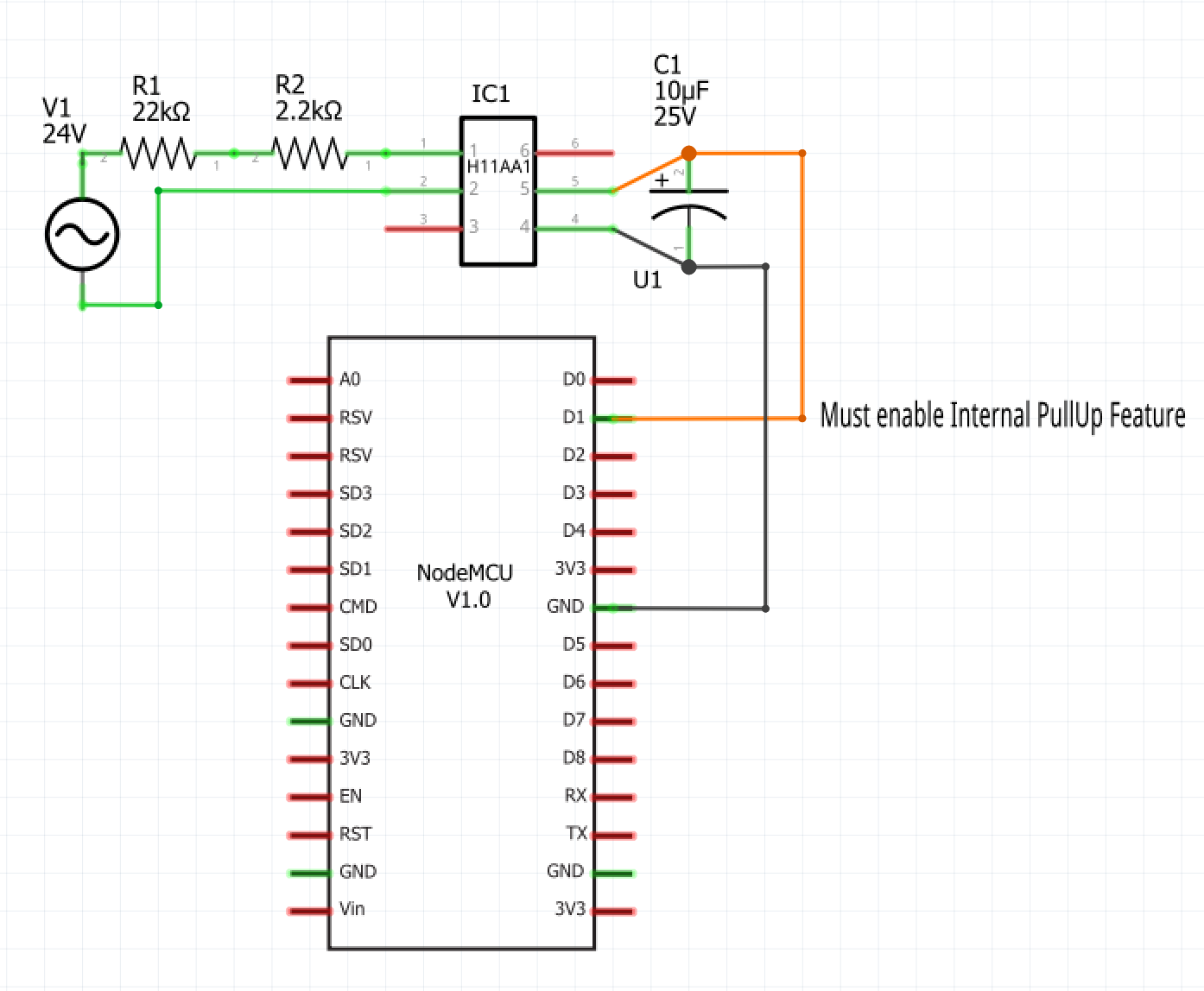
Here is the circuit for monitoring a 24VAC signal. It requires a little bit of engineering to convert the AC voltage into a DC on/off signal.

(Note: The below wiring diagram is actually for an ESP8266 based NodeMCU board. However, the important part is the AC to DC circuit.)

I'm seeing if i have enough brains to incorporate HX711 load cell sensor into Hubduino....
Questions..

  1. there is no weight capability defined and I need to have the commands "tare", "calibrate" and probably refresh..
    What is the best way to accomplish that ? (is there ways to define commands outside of defined capabilities?)
  2. In the hubduino code I assume I need a constructor, destructor, init and beSmart right ?
    Where does refresh and update fit in ? Is update what is called every loop through? If so what is refresh for?
    Thanks for any clues...
    Tim

Dan, am trying to follow your 2nd option of catching the results of the Ultransonic sensor and the temp sensor and then modifying the distance BEFORE its sent back to Hubitat. I cant, for the life of me, figure out how the Callback function is called from the Everything.cpp.. I just wanted to understand a little more before i modify my version of the ST_Anything..
Also, I attempted to visually trace how messages might be sent to Hubitat (through the Everything object, right ?), but can Hubitat send messages back to the MC ?? if so, is there a listener somewhere ?

Yes, you can create custom commands in a driver. You should be able to create a new custom Child Driver, that implements as many custom commands as you’d like.

Use an existing ST_Anything device as a starting point on the Arduino side.

Refresh is a command accepted by the Parent Device. It causes all devices on the Arduino to send an immediate status update to the Hubitat hub.

Take a look at the PS_Voltage.h and .cpp files. This is a simple example that should help you understand the architecture. Within the .cpp file you’ll see a function named beSmart(). This is what receives commands sent from the Child Devices. Take a look at the Child Switch driver to see how to “send” a custom command to the device’s beSmart() function on the Arduino.

Have fun. Once you review and understand the architecture, it really is fairly simple. This assumes you as proficient in C/C++ programming. :wink:

You should not need to modify any of the ST_Anything library files. All of the changes should be possible in your sketch.

Upon further refreshing of my memory, I think you’ll need to simply handle everything in the existing callback() routine of the sketch.

  1. catch and cache the temperature value
  2. when a new ultrasonic1 device value comes in, calculate a temperature compensated “ultrasonic2” value
  3. send the “ultrasonic2 value” string to the Hubitat hub.

So, this will create another Child Device on the hub with the temperature compensated value.

Yes. That is exactly how all executors work. Hubitat send a command to the microcontroller, and the Everything class then calls the correct device’s beSmart() function.

The communications on the Arduino side are all abstracted away from ST_Anything by the appropriate “SmartThings...” libraries. No need to modify any of that code either.

Dan thanks for this.. I've been at it for a few hours but not making progress, gonna goto bed but from what i see the Callback routine is called "after" the string is sent to Hubitat, in Everything::sendStrings()

image

So If I do change the &msg in Callback will it be sent to Hubitat ?

Thanks for all your advice - I really appreciate it.. and i find myself enthralled with your entire ST_anything Hubduino process - loving it...

No, you can not change the &msg in the callback() routine of the sketch. However, we don't need to.

Here is an example of what I was trying to explain above. I used a PS_Voltage device as it was the easiest thing for me to setup for testing. You would of course use the PS_Ultrasonic device. Anywhere in the example code below that you see 'voltage1' or 'voltage2', replace with 'ultrasonic1' and 'ultrasonic2'. Also change the '9' to '12' in the string manipulation code.

NOTE: Do not create a separate 'ultrasonic2' device in the setup() routine. The callback() routine is basically tricking the Hubitat hub into believing there are two ultrasonic sensors, the original, and the temperature compensated.

void callback(const String &msg)
{
  Serial.print(F("ST_Anything Callback: Sniffed data = "));
  Serial.println(msg);
  
  //TODO:  Add local logic here to take action when a device's value/state is changed
  if (msg.startsWith("voltage1 ")) {
    String value = msg.substring(9);  //9 is the length of "voltage1 "
    value.trim();                     //make sure no trailing spaces are present
    float val = value.toFloat();      //convert string value to float val
    val = val * 1.5 + 10;             //simple linear conversion as example algorithm
    Serial.println(val);              //debug to Arduino IDE Serial Monitor Window
    String strMsg = "voltage2 ";      //build base message for NEW voltage2 device
    strMsg = strMsg + val;            //include the new, adjusted val
    st::Everything::sendSmartString(strMsg); //send this new data to the hub, which will create/update a new "voltage2" child device
  }

Hopefully this makes it clear. When it comes right down to it, all the HubDuino Parent device cares about is a simple space delimited "name value" pair. So, we can easily make one up in the callback() routine using data that is 'sniffed' from other real sensors.

Hi Tim,

I’m in the middle of doing this to set up a bed occupancy sensor along the lines of this.

So far all is going well. Scales are reporting weight to HE, and I have tare working, as a command in the device and scheduled every day. The load cells are not in their final position under my bed yet, and I’m still tweaking but it has gone well so far using the Hubuino stuff (big thanks to ogiewan).

Malcolm

1 Like

@malcolmcdobson / @tim.ocallag, nice to see more people interested in using the HX711 with Hubduino!

Keep us posted and the way you guys are going and it looks like when I finally get my order in, the code might already be written, oh well, I'll find another sensor to code :wink:

1 Like

@malcolmcdobson
That is awesome ! I will study what you did and may have some questions !!

I hate to bother you more........from what i see, the capabilities are what dictate what commands show up in the devices page.... its unclear how I would create a tar and a calibrate command in the child driver....is there any examples of commands created that are not part of a defined capabilities...wait...i did stumble upon this (below) so can I create a command with the command statement ? Still curious about examples in Hubduino... Also looking at the PS_Voltage there is no update() or refresh() ....just getData().... does a user somehow have to do something to get getData invoked?

        //demo commands, these will create the appropriate component device if it doesn't already exist...
        command "childSwitchOn"
        command "childSwitchOff"
        command "childDimmerOn"
        command "childDimmerOff"

to be clear ...im trying to understand how to create commands on the devices page

That terminal board with the socket is exactly the type of thing that will help me simplify this build. Thanks!... and I'm sure I'll be back soon for help with your app.

Yes, you can create custom commands and custom attributes.

refresh() is a command in the HubDuino Parent Driver. On the Arduino side, it ends up literally being a string, "refresh", that is received and handled completely within the Everything class. Once Everything receives a "refresh" command, it then calls the refresh() routine in every ST_Anything device. What you're probably missing is the fact that each ST_Anything device has inherited methods and properties from its parent class, and so on, and so on. In the case of 'PS_Voltage', which inherits from 'PollingSensor', you have to look at its parent class to find the following...

	void PollingSensor::refresh()
	{
		getData();
	}

Makes sense?

As for update(), that is typically only implemented in 'InterruptSensors', not PollingSensors. InterruptSensors are woken up every pass through the Arduino loop() routine, so they can check the status of GPIO pins for a change of state. PollingSensors are woken up based on a certain amount of time elapsing.

It can be a little confusing if one is not an experienced C++ programmer. :wink:

So, in your case... You want to implement some custom commands. Those are created in a new "Child Weight Measurement" driver. Something like

command "tare"
command "calibrate"

.
.
.

def tare() {
    sendData("tare")
}

def calibrate() {
    sendData("calibrate")
}


def sendData(String value) {
    def name = device.deviceNetworkId.split("-")[-1]
    parent.sendData("${name} ${value}")  
}

Then, in your new "PS_HX711_Weight" class on the Arduino, you simply need to handle receiving the "tare" and "calibrate" messages in the beSmart() routine.

1 Like

The author of that article “DIY Bed Presence Detection in Home Assistant” is Zach Lalanne.
Another helpful post on this topic by Lewis Barclay is Building a bed occupancy sensor for Home Assistant. He’s also made a YouTube video which was where i first got interested in doing this. The YouTube link is https://youtu.be/VCEgeDN0RLw.

@dylan.c
Here is a board I just got, if you don't mind soldering ... and I suppose when they are back in stock

https://www.amazon.com/dp/B089M4Q5GB/ref=cm_sw_r_cp_apa_fabc_XK1cGbDDHWG98?_encoding=UTF8&psc=1