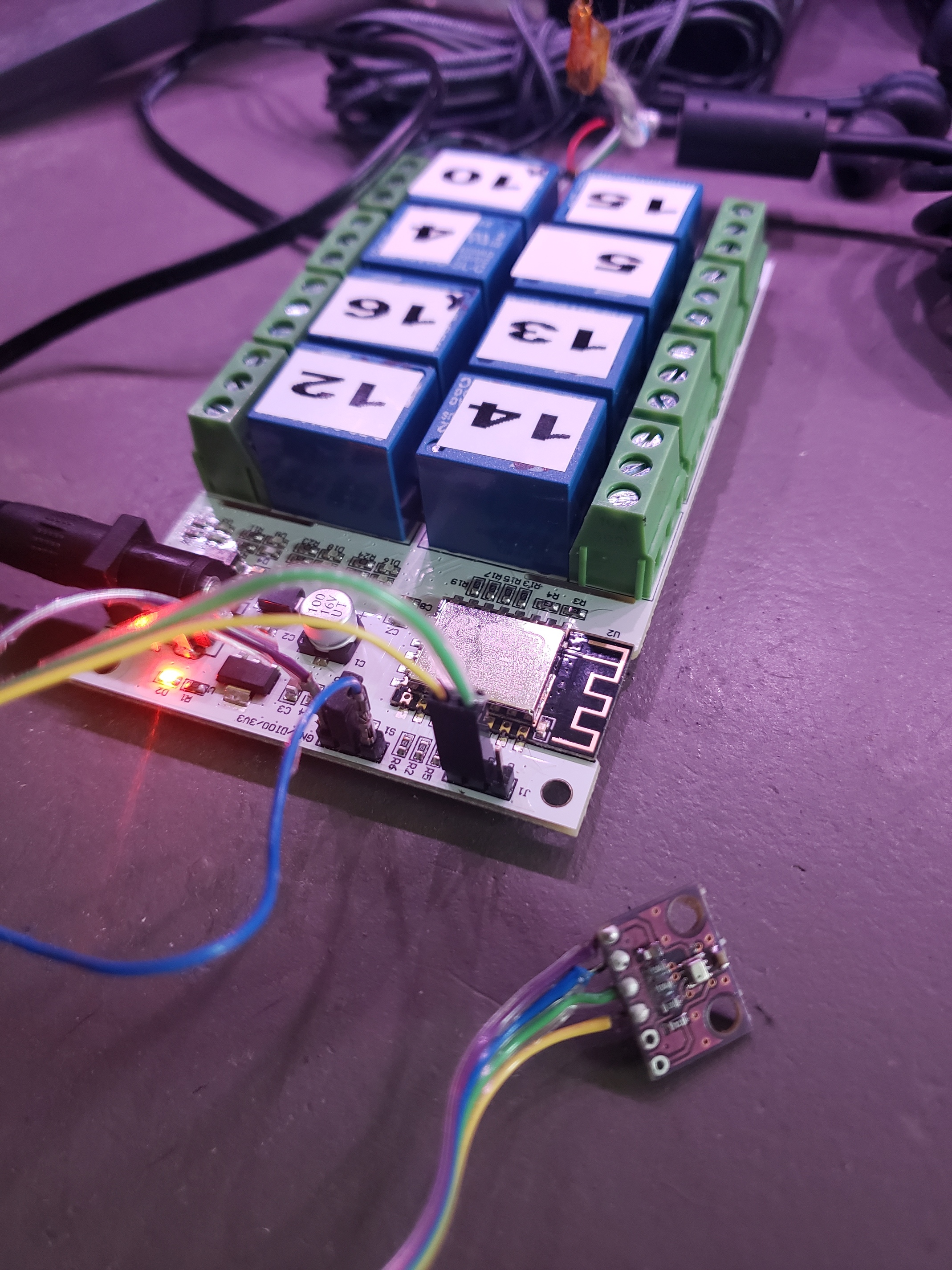
@ogiewon I just got a little crazy tonight and built a 12 input power monitoring esp32. I have to finish the assembly and testing, but code seems good and devices show in HE. I am using current clamps and a small circuit to allow the esp32 to read the power in each one. I have tried 1 clamp so far, and it is working. I figured that if I was going to be in the electrical box, I might as well make it count! My Prusa MK3S will be here in about a week, so once that is up and running, I will print a case and wire up the rest of this power monitoring unit.
2 Likes
All - I am looking for a few volunteers to beta test a new version of my HubDuino Parent Ethernet Driver. I have figured out some methods to reduce the amount of manual input required when setting up a new HubDuino Parent Device. I have also added a device health/status feature in the form of a Presence Capability for the Parent Device. If Hubitat has not heard from the microcontroller for 15 minutes (user setting), then the presence status goes to 'not present', otherwise it shows as 'present'. You can then set up a Rule to notify you if one of your HubDuino devices has gone offline. I also automatically configure the 'numberOfButtons' attribute based on what is sent up from the microcontroller.
Since this version eliminates the need for manual input of the MAC address, and thus changes the parent's Device Network ID, I also made changes to how new child devices get their DNI assigned. I have everything working and tested and I believe this version should be 100% backwards compatible...but you never know until some additional users give it a try. Newly created HubDuino Parents and Children will utilize the new DNI design. One big advantage of this new design is that you'll be able to swap out the microcontroller hardware with a new board, without having to change any of your Hubitat automations. This will only work for newly created HubDuino instances. Legacy HubDuino instances will still have child devices that are tied to the original microcontroller's MAC address as part of their DNI.
If interested in helping test this new code, please Private Message me and I'll provide the source code changes. Note - these changes are not minor and thus there is some risk involved. You may end up having to recreate your HubDuino instances from scratch and thus tweak every automation that uses these devices. I have made every attempt to prevent this from happening. However, due to this risk, I am asking for some volunteers who are willing to help test using non-critical HubDuino instances (like running one on your workbench.)
Thanks!
3 Likes
I am really diggin' the Hubduino. First of all, is there a place to donate? Your effort is totally worth my money.
I have on MKR1010 set up with a simple relay to activate a standby generator. However, I am trying to make this better by also monitoring voltage and current output. I can successfully hook up the code between MKR1010 and HE so that I can see my child devices. What I am having a problem with is voltage. My sensor is a simple transformer, so its alternating. My voltage readings in Hubitat are all over the place, I'm thinking the voltage reported is not RMS, but some instant in time?
Emonlib does a great job of doing all these calculations. I'd hate to reinvent the wheel. Is there a way to override a variable being sensed by a sensor in the arduino code?
No donations necessary. I prefer to keep this a hobby and not a business.
Yep, this makes sense. The PS_Voltage device only supports DC Voltage measurements.
The PS_Power device actually uses the emonlib. However, it does not currently support Voltage Transformer readings.
For a simple generator circuit, just a CT should be enough.
How does this work with multiple hubduino’s? I currently have two Arduino Megas and an esp8266.
Just add a HubDuino Parent Device for each microcontroller. Each microcontroller must have a unique IP Address and MAC address.
Thanks for the feedback. No problem about the voltage. I’m already using the PS_Power to monitor my CT’s and it works well. Is there a way to combine the output of two CT’s to appear as one? It’s handy to see total generator output instead of trying to follow both legs and summing in my head.
I’d love to do this on the Arduino but not sure how this fits into “Everything”. Not sure if this is better handled on the HE? I’m a new HE user and haven’t quite figured out how inputs can be handled.
If you use one CT that is large enough in both diameter and Max Amperage, you can actually run both Hot Legs of the generator through the same CT, as long as one wire goes through from left to right, and the other wire goes through right to left. So, instead of cancelling each other out, they will be added together. I use this technique with my IotaWatt.com devices as even with 14 CT inputs, I have more breakers that that. So, I'll combine 2 x 20A breakers through one 50A CT, for example.
Happy to test. Let me know what you want me to do
I have a few DHT22 Temp/Humidiy sensors connected to Hubduino. Not actually needing to rely on it yet, I have one of them that has been at 82.6 degrees for several days. The old fashioned alcohol thermometer next to it says 60. I haven't looked at the serial monitor yet to see if it is sending the correct info. But in case it isn't, is this a case of you get what you pay for? I probably have a very cheap one. If this is the case where is a good place to get reliable sensors?
Thanks
I have not had the best of luck from DHT22 sensors. I have started to rely on DS18B20 temperature sensors, as well as the BME280 and AM2320 I2C sensors (both do temperature and humidity). These seem to be much more reliable than the DHT22 sensor.
YMMV of course!
After doing a power reset on the arduino they all came back online. I had a BME280 outside and it also needed to be reset occasionally. Maybe I just have a jinxed house. The most stable has been the DS18B20 devices I have used, the humidity was an added attraction
I bought a LinkNode R8 and have st_anything running on it. I added a bmp280 and have that running great. I how ever would like to use the door control but only have gpio 0 and 2 left to connect a contact sensor too. From what I read GPIO_0 fails at boot if pulled low and GPIO_2 is high at boot but also fails if pulled low at boot. Anyone know any work arounds besides not using one of the relays?
You can use GPIO3 configued as an input if your RX pin is exposed on the header. This would mean you would not be able to use the Serial Monitor anymore to do any debugging though. But both GPIO3 and GPIO1 are available as RX and TX. You would just need to add a line to your sketch (I believe in the setup and in the loop) declaring the pinMode for these by using:
pinMode(3,INPUT_PULLUP); // if you were going to use the internal pullup for the contact sensor
pinMode(3,INPUT); //if you're not
That should allow you to connect your contact sensor to the RX pin. However, you would want to turn off all debugging in your sketch also. This will prevent you from using the serial monitor.
I am using 3 and 1 for the bmp280 I only have 0 and 2 left. I have tried using i2c on the 0 and 2 pins but it would not boot. I think I will have to get rid of the of the relays to expose a useful gpio 
Yeah, that sound like the only available option. That is the limitation of these style relay boards. They only are really designed to be used as relay devices. A regular NodeMCU or WemosD1 wouldn't have give you this trouble.
I love my last project with st_anything_power_meter esp8266
Power metering my dryer and after dryer done sending voice to alexa...
But is it possible to
Change from: 0.00 to 0
And
Add to child king of meter history energy used today kwh
And add how many $ spent
Sure, all those things are possible. ![]()
The real question is are you up to the challenge of making those changes to your copy of the Child Power Meter driver code?
Sorry, but I personally do not have any time to work on those changes. If you're not a programmer, this would actually be a good little project to learn some groovy. It would all be contained within the child power driver code.
Never made any programmer's things bebore .. But i can try... At least try find info online... And i need "try" change only sketch or driver too???
I would try to contain all of your changes to the Child Power Meter groovy driver code. Leave the Arduino code alone... ![]()
For example, if you want to remove the decimal places from the reported power level, try this simple modification:
on line 67 in the following driver code, change
sendEvent(name: name, value: value)
to
sendEvent(name: name, value: value.toInteger())
as this should drop the fractional portion of the value.

