That's great news. Thanks Dan!
That's a good point. Those will be handy to have around. I'll order some.
Appreciate the .ca link too 
1 Like
Thanks for the head's up on the MAC address. That would have been rather tough to find.
Just to chime in here I have used Hubdino with the nodemcu and the 2 channel version of the 4 relay unit shown above for my garage doors. Works perfectly! There is also the D1 Mini version of the nodemcu that has a single channel relay shield that stacks on top of the D1 mini.
I have also flashed Hubdino to these outlets. Need to be able to solder though.
2 Likes
Really?!?! I've been looking for a couple cheap outlets for Xmas lights and things like my air fresheners (i'm gone for weeks at a time...no sense the house smelling nice for nobody). Do you have a walkthrough on how to break these down to flash them? That would be awesome!
The procedure is not for the faint of heart. I'll give you a quick guide.
-
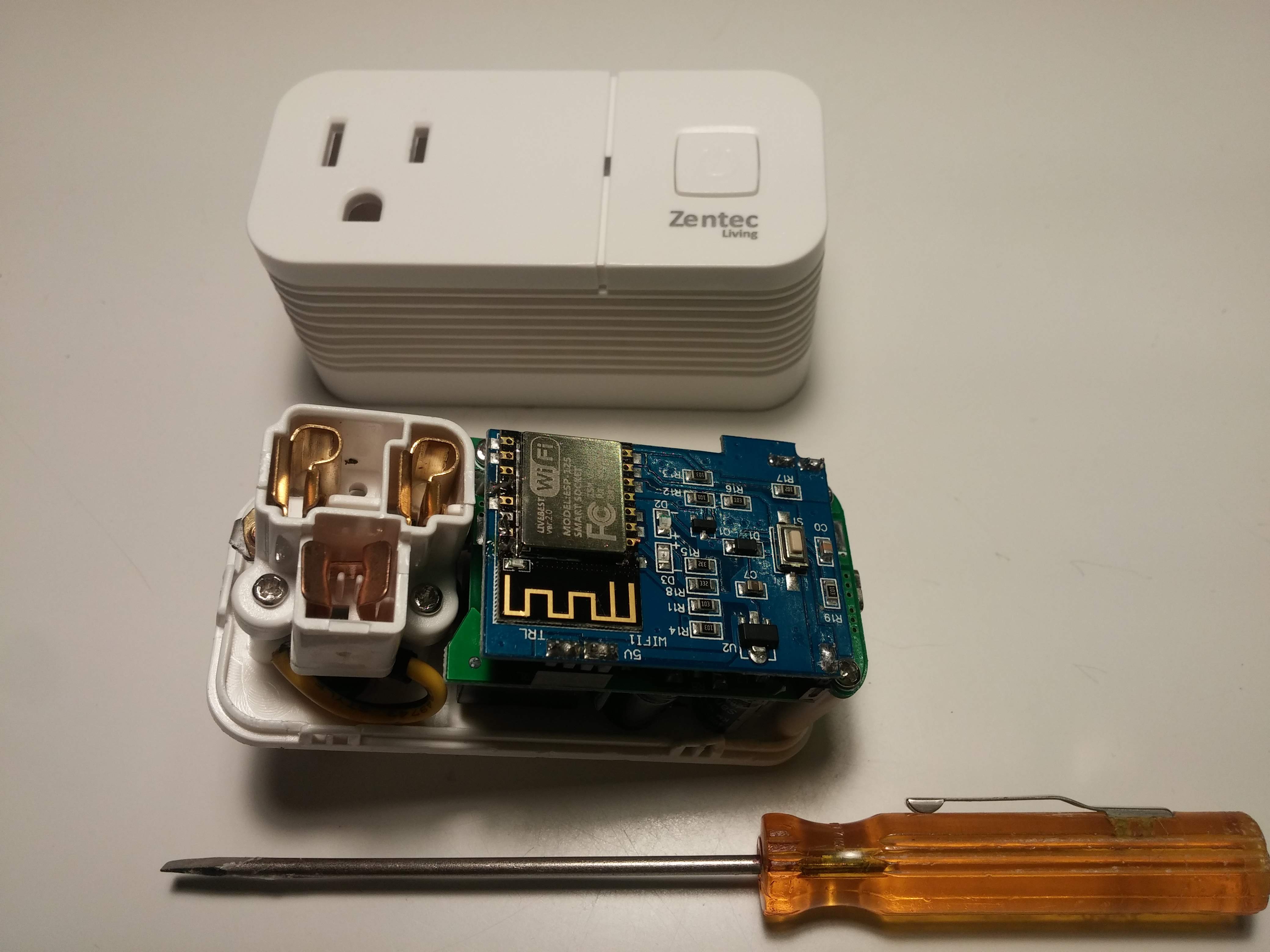
You need to pry the case open with a couple of small screwdrivers (like precision screwdrivers). I start at the side where the USB port is. It can be done without damaging the case but it may get a little marred on the backside.
-
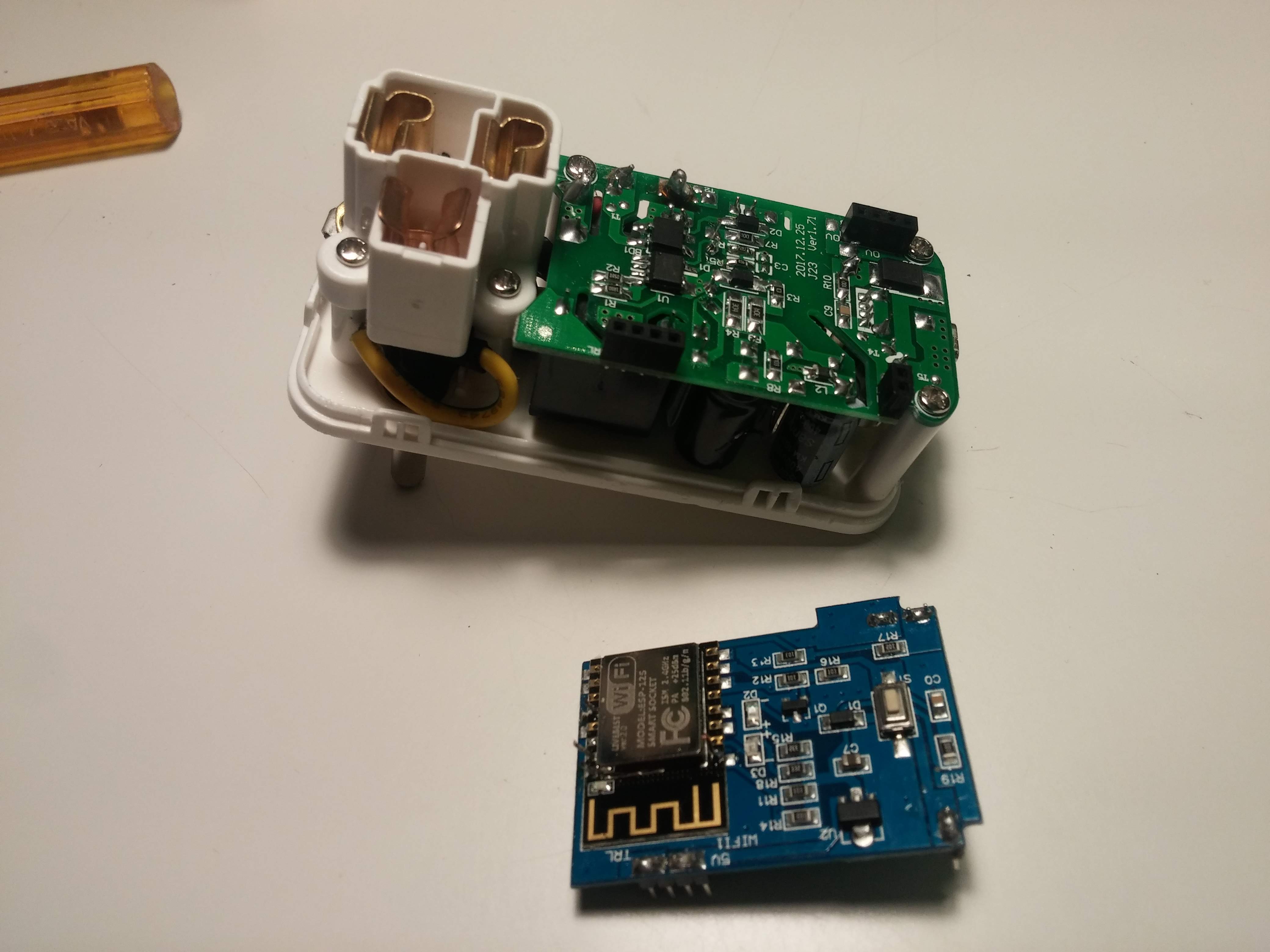
Inside you'll find a nice little ESP-12 module sitting on a circuit board that plugs into the main board which can be unplugged, and powered with a 5v supply and flashed with a usb to ttl module as linked to earlier. You will also need some 26 or 28 gauge solid wire, (I used some cat5 wire), and 2 momentary pushbutton switches, a small breadboard helps too.
-
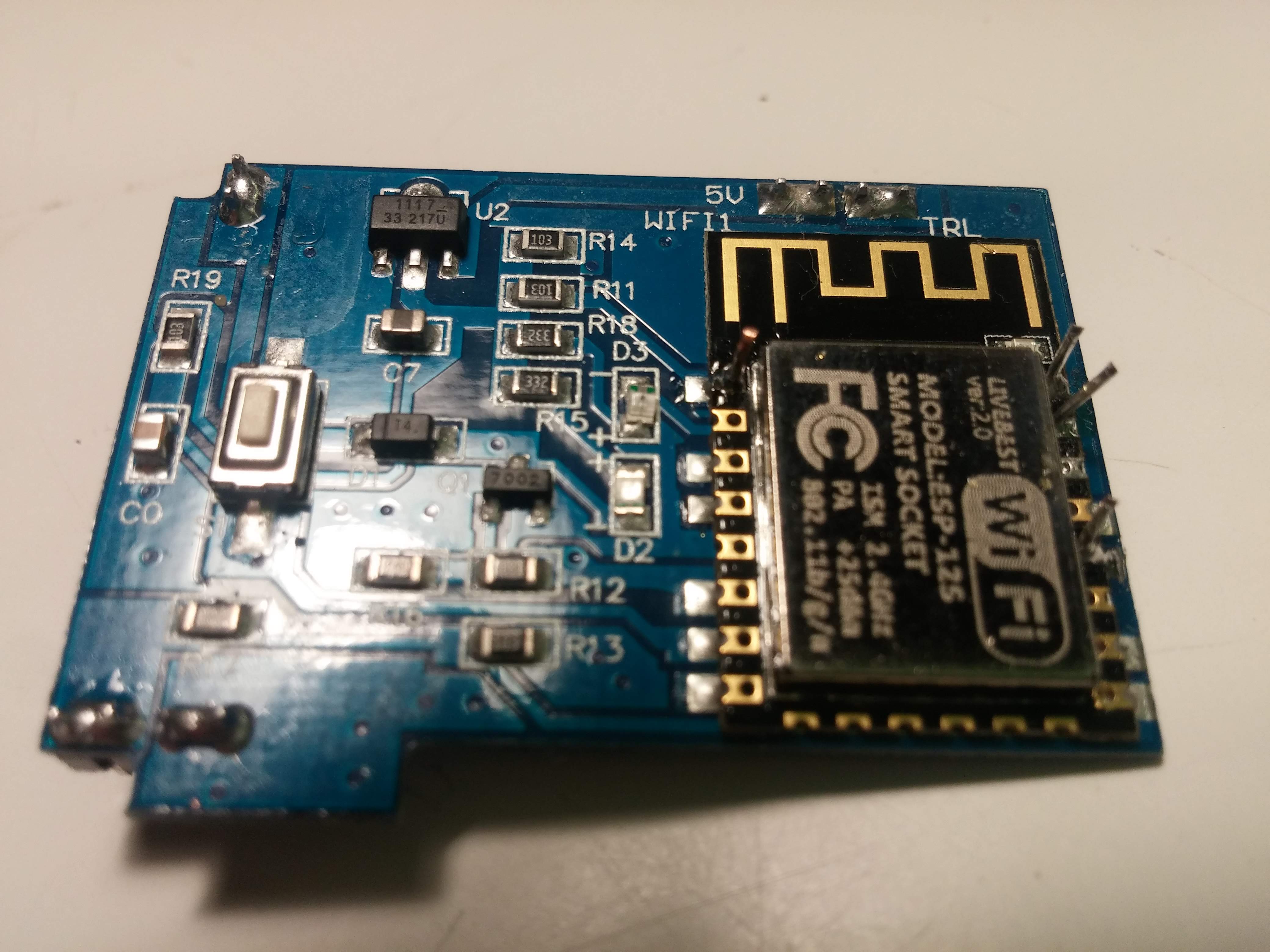
The ESP module on the removable board follows the standard pin outs. If you orient the board with the esp module to the right with the pcb antenna on the top. the pins are as follows: Top left = reset, top right = TX, right side next pin down = RX, right side 5th down, gpio0 hold low during reset to enable flash. There are small holes that the the cat5 wire will fit into (then solder in place, you can see them in 3rd picture) that will enable you to use test clips to connect to the pushbuttons, and usb/ttl module to enable to to reset and flash the chip. Make sure you get a usb/ttl module that is 3.3v compatible. I used this exact one: https://www.amazon.com/gp/product/B075N82CDL
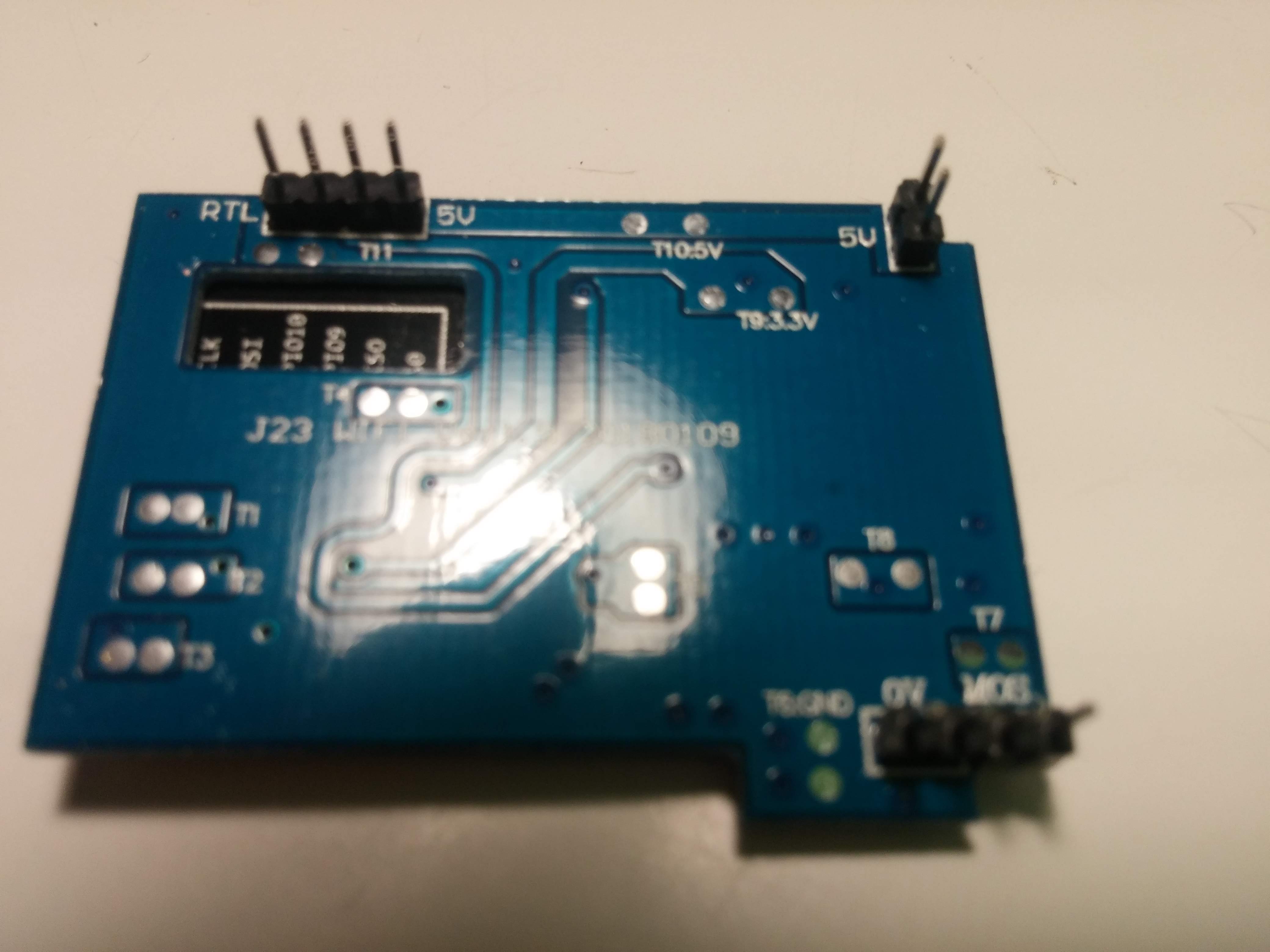
On the back of the module you'll find two headers one labeled "5v" (5v positive) (top right last picture) and one labeled MOS (ground) (bottom right last picture). These can be used to power the device during programming. The other header (top left) connects to the relay.
To flash the esp you have to connect gpio to ground (through pushbutton) then connect reset to ground (through pushbutton) then release reset while still hold the flash button for a few seconds. You should be then able to upload the code from the Arduino IDE. You have to set the IDE to "generic esp8266" and the flash size to 1M.
Heres the clips: https://www.amazon.com/JIUWU-Test-Ideal-Electronic-Experiment/dp/B00NHG8Q5U
The relay is on GPIO12 "low" is off, the button on the outlet is on GPIO13.
I have 6 of these running now with 4 more on the way. NOTE: The first 6 were the Zentec brand (insides pictured in this post).
The ones i linked to above are en route but the case looks identical so as with most chinese stuff they should be identical inside.
I also added a DHT22 temp/humidity module to one of the switches. My basement dehumidifier is connected to it. I doesn't look glamorous but it does the job.
Here's some inside pictures:
1 Like
Thanks! Since you only have to solder in the TX and RX it's actually not all that bad. Since you have to pull GPIO0 and RST to ground to get the module into flash, that should be easy enough to do with test leads rather than soldering them in. And since there's a ground pin on the back, that would be easy to set up (I build myself some test leads with dupont connectors on the other end. It's not like you have to remove the whole ESP module from the board. They're only $7.99 so I think I might pick one up and give it a try. Thanks so much!
Your welcome, I ended up soldering leads to reset and gpio0 also because I was not able to get the test clips to stay connected. Buy the 2 pack it drops the price to $7 ea.
yeah...I meant like straight, needle-like leads.
Since you're only connecting to reset and GPIO0 for a second. RX & TX need a much firmer connection though.
It's too bad that they USB port didn't serve a dual role in this case to also allow you to program the board. but that would have made it WAY too easy. 
After a reread your post that's what i thought you meant. Real credit goes to the creator of the Hubdino code. I just got lucky on these outlets as when I bought the zentec brand they were the cheapest I could find.
1 Like
We couldn't get THAT lucky. The usb port is nice though (always on) as I have it powering a nodemcu that's hooked to a high torque servo that opens and closes my window blinds. 
1 Like
No support for Raspberry Pi in HubDuino/ST_Anything. OmniThing does support RPi and many other platforms.
Question - semi-on topic. 
I have need to put an esp8266 outside. I have a contactless level sensor that I want to put on my pool's bleach tank for low level detection.
I poked around in the arduino IDE 6 months ago when I got the level contact sensor, and it looked like it should work (I saw the state change as expected when using it on a coke can ) . Then I got busy and never did anything with it.
Does anyone have any suggestions for enclosures for an ESP that would be suitable for outdoor use?
EDIT: Oh, and I guess it doesn't HAVE to be an ESP8266, I just said that because I have an extra one laying around.
While not exactly small... the following enclosure is nicely designed and includes an GFCI outlet internally. It is designed to house an outdoor sprinkler controller. It has a removable plate that can be used to mount your electronics to, and allows for cable management behind the plate.
https://www.amazon.com/gp/product/B000VYGMF2/ref=ox_sc_mini_detail?ie=UTF8&psc=1&smid=ATVPDKIKX0DER
Do you have a link to the exact model of sensor you'd like to use for this application?
Here's a non contact sensor I was looking at for another project. Simple on-off when level drops.
https://www.amazon.com/Contact-Liquid-Level-Sensor-Switch/dp/B074KB93N7
For an outside enclosure go to your local Home Depot, Lowes, Menards and look for something like this:
https://www.homedepot.com/p/BELL-1-Gang-Non-Metallic-Weatherproof-Gray-Box-with-Three-1-2-in-or-3-4-in-Outlets-PSB37550GYB/202284546
I have one of these:
And one of these:
https://www.dfrobot.com/product-1493.html
I didn't test the one from amazon, but I did poke around on the one from DFRobot, and it seemed to work.
The first device can be handled as a contact sensor in HubDuino. You'd need to make sure that the Internal Pullup feature is disabled, as the device outputs either 0v, or Vin. The only issue I see if that the minimum voltage is 5V. Trying to use this with a ESP8266 will require a level shifter to keep the voltage in the GPIO pin between 0v and 3.3v.
The second device also looks like it could simply act as a HubDuino contact sensor. It appears to look similar to the first one, requiring 5v, and output 0v or 5v. Again, the level shifter would be a safe bet when using an ESP8266 board.

