One last question on the sketch...you have it mapped to only go up to 4? Why is that exactly? That isn't right is it? Wouldn't i want to do this instead:
Edit: I should have multiplied instead of dividing in these calculations. The error is corrected in a later post.
See my previous comments on using a half wave rectifier (divide by 2) and voltage drop due to the diode forward voltage (divide by 2 again). I divided 15.84 by 4, then rounded to 4 because the second divide by 2 is a guess on how much the diode will drop the voltage. I'm also ignoring a peak to peak voltage conversion to RMS that is going on with this circuit that offsets things the other way a bit.
This will not give a precise reading in kilowatts, but should be good enough for determining if the dryer is running.
15.54 vs 4 is not critical to see if the circuit works. Just look for near 0 reading with the device disconnected, and increasing values as load is increased. Adjusting the 15.54 or 4 value can be done later if you want to dial in the accuracy of the reported power consumption in kilowatts.
Do you get near zero with the hair dryer off?
What is the power rating of the hair dryer and the reported power consumption?
Dan's calculation for power consupmtion was for the dryer at 240V. The hair dryer is 120V, so the 15.84 scaling factor he gave you would be cut in half to 7.92 for the hair dryer. I checked my math and notice my adjustments for the rectifier circuit are incorrect. I divided when I should have multiplied.
For your dryer I suggest:
static st::PS_Voltage sensor3(F("power1"), 15, 0, PIN_VOLTAGE, 0, 1023, 0, 64, 10, 100);
For your hair dryer:
static st::PS_Voltage sensor3(F("power1"), 15, 0, PIN_VOLTAGE, 0, 1023, 0, 32, 10, 100);
I ended up going with the following:
static st::PS_Voltage sensor3(F("power1"), 15, 0, PIN_VOLTAGE, 0, 512, 0, 16, 10, 100);
That gave me readings of that maxed out around 8 or 9. However, there are some very strange things I learned about my dryer.
It doesn't heat with a lower power on the low-heat cycle. It just turns the heater on less often. I'll have to watch what the numbers do for a full dryer cycle.
Tumbling and Off are COMPLETELY indistinguishable with this method of sensing. I got readings below off when it was spinning with no heat. I tried all 3 wires and different orientations of the transformer and nothing was able to detect both the heated cycles and the spin-only cycles. I don't use no-heat very often so that isn't a deal-breaker. But it is very, VERY odd.
I'm using global variables in conjunction with a webCoRE piston running on the ST cloud to capture the readings in Google Sheets while it's running. So, I will report back what i see once I run a full dryer cycle, most likely later today or tomorrow.
Thanks for all your help and wonderful suggestions.
@ogiewon, when you get the new device type ready for Hubduino, def let me know. I have a great test bench now for beta testing. The split-core transformer has a mini plug on the end of it and I have a bunch of TRS adapters so I could def swap over to a "test" board to test it out for you.
@Ryan780 - I have uploaded a new device class called PS_Power and the associated EmonLib library to my GitHub. I also created a simple example sketch called ST_Anything_Power_ESP8266WiFi.ino that you can use to test with.
You will need to adjust the number of samples and the CAL values in the constructor to suit your needs and CT.
If you read up on the Emon Library you should be able to glean some information on these parameters. You can use the default number of samples (1480) as a starting point. The CAL contstant will probably need to be tweaked to ~20 for your SCT-013-020 CT as I used a SCT-013-030 for my testing.
The results are consistent, however not very accurate with no power flowing. I think you should be able to use it for monitoring a washer or dryer, but not for calculating true energy usage. Without a second analog input with a calibrated voltage reference, the accuracy of this will be limited. But since it seems to be consistent, it might be alright for your use-case.
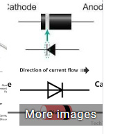
Okay, so I shouldn't use the circuit with the diode that I built yesterday? @VooDooFiveTwo, if I was going to use a 6.3v 1F capacitor, what value should I use for R1 and R2? If you want to share how you're calculating that, I could probably reproduce it myself, i just have no idea what formula you're using.
@ogiewon I will probably not have time to give it a try until this weekend. I will be out of town on a business trip for the rest of the week. But thanks a bunch for working this out!
@Ryan780 based on your previous comments, I think you have components on hand to match the example circuit values. That's what I would recommend given it has been shown to work.
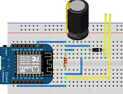
Your suggested 1F cap is overkill, but I don't think it will harm circuit function. Did you intend to type 1000uF? Even that is larger than needed . For this particular circuit, the two resistor values should be equal. The effective wemos A0 input impedance is roughly 320kOhm, so you want to keep the sum of the two resistors significantly less than 320kOhm. The two resistors at 22kOhm is a good upper limit. The other consideration is keeping the current draw from the 3.3v supply less than 1mA. That means the sum of the two resistors should be at least 3.3kOhm, so 2.2kOhm each would work as a lower limit, but higher would be better. You could consider calculation of low pass filter cutoff frequency, but with the big caps in play here, the frequency is very low relative to the 60Hz noise that is being introduced on the voltage divider.
In summary, resistors equal in the range 2.2kOhm to 22kOhm will work. Capacitor value at least 10uF will work. No need to go crazy big.
And to be clear, the first circuit I gave you only works with the newly created PS_Power device class. The second circuit (with diode) only works with the PS_Voltage device class. They cannot be interchanged.
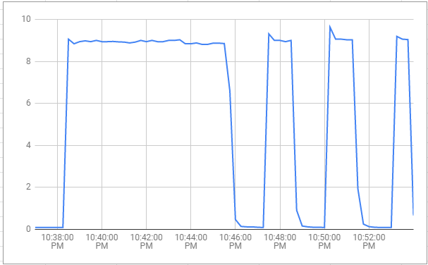
I didn't do a full cycle but I did a short one and what I got is a little surprising.
It seems that my dryer only has two states, heating or not. I figured it would just heat at a lower temp to keep it hot in the dryer but I guess I was wrong.
Btw, I pulled this out using RM and a global variable. That is sent to ST and webCoRE (don't have my hub plugged in, just use the cloud). webCoRE then takes the data and passes it off to IFTTT in the correct format to add it to Google Sheets. Easy peasy. I know that some folks are using InfluxDB to record data. Seems that this might be less labor intensive for the hub, depending on how many sensors you want to capture and how often.
I am going to build the other circuit that @ogiewon detailed earlier and try again this weekend.
I also kept the reporting at 15 seconds but built logic (using the callback) to put the board into deep sleep when not in use. Then, I wake it up with a button wired to the rst pin. I wired an LED that automatically turns on I'm then able to capture all the data only when the led is on. Then, when I turn the LED off, the callback put the board to sleep. I figure that's better than having it report all that unnecessary data to HE. Have everything wired to a proto-board for my D1 mini so I can swap out the board if I want to. I'll take a pic of the final product when I get my project box all squared away. Gotta get the Dremel out this weekend.
Be sure to record some time at the end of the cycle where you are trying to determine that the cycle is complete. I think you might be able to get a better look at the signal with one of these device configurations.
Even with the data you collected, looking for a value less than 1 for more than 2 minutes would give you an indicator that the dryer was no longer running.
Edit: looking at the data more carefully, I see a couple things. The transition from heater on to heater off has a shape that is likely driven by the low pass filter frequency being extremely low. I would reduce the capacitor size to address this.
Your dryer has 3 states:
off
motor on
motor and heat element on
State 3 is easy to see. The magnitude of state 3 is so large compared to state 2 that it makes seeing state 2 on the plot very difficult. I wonder if you could distinguish the difference between state 2 and state 1 if the existing data was plotted with a vertical axis maximum of 1 instead of 10. State 3 would be off the chart, but that's ok.
Well, that's where it gets tricky. I don't really need to distinguish between 1 and 2. The dryer keeps spinning long after the cycle is complete to prevent wrinkles. I would want to be notified that it's complete then. But on other settings both the heat and the motor turn off simultaneously. So, it's really not an issue distinguishing between the two.
You might be able to use filtering to keep the reported value from getting near 0 in the 90 second period that the heater is off mid cycle. There are two ways to try this:
-software: last term in the sketch function call can be set to 5 for maximum filtering
-hardware circuit: keep your big 1000uF capacitor and increase the resistor value. Try 100kOhm.
If you filter to dampen the 90 second signal drop, you will also see that much of a delay in response at the end of cycle.